Article

Study on Inertia Load Resistance Analysis Method of Light Truck Door Latch

School of Mechanical and Electronic Engineering, Wuhan University of Technology, 122 Luoshi Road, Wuhan 430070, China
*
Authors to whom correspondence should be addressed.
Appl. Sci. 2022, 12(9), 4171; https://doi.org/10.3390/app12094171
Submission received: 21 March 2022 / Revised: 17 April 2022 / Accepted: 18 April 2022 / Published: 21 April 2022
(This article belongs to the Special Issue Structural Design and Computational Methods)

Abstract

:
Aiming at the problem of door opening caused by the unlocking of the side door latch system under the action of inertial force when the car is in a side impact, this paper takes a light truck door latch as the research object, and proposes an inertia load resistance analysis method combining theoretical calculation and simulation analysis. Through the theoretical calculation of inertia load resistance of the door latch, the force of each part and the rotation of the pawl are analyzed. We perform inertia load resistance simulation analysis on the latch to verify the reliability of the theoretical calculation results. If the theoretical calculation result is that the latch will be unlocked under the inertia load of 60 g (588 m/s2), we compare the force of each part in the theoretical calculation process with the normal opening condition of the latch to provide a basis for the optimization of the latch structure. Finally, theoretical calculations and a simulation analysis are carried out on the optimized results again, and a latch structure that meets the requirements of the inertia load resistance is obtained. Since the results obtained from the inertia load resistance simulation analysis are basically consistent with the theoretical calculation results of the inertia load resistance and the inertia load resistance simulation requires a lot of computing time, after the verification of the inertia load resistance simulation analysis, firstly, the inertia load resistance simulation step can be omitted in the subsequent structural optimization process.

1. Introduction

Vehicle side impact is a common type of accident. According to the World Health Organization’s 2018 statistics, about 1.35 million people die in traffic accidents every year around the world, and in the car-to-car side impact, the passenger’s death risk is 85% at a speed of 65 km/h [1]. In a side impact accident, if the door is opened abnormally, it will increase the risk of the driver and occupant being thrown out of the car and foreign objects entering the car, causing injury to the driver and occupant. Therefore, car door locks and door hinges play a very critical role in ensuring the safety of drivers and occupants.
At present, relevant studies have been carried out on the abnormal opening of side doors caused by side impact. In terms of the door opening caused by the inertial force of the door latch system, Qianghong Li et al. [2] analyzed the difficulties of the calculation of the inertial load resistance of the door locks and put forward a solution. The calculation process was given, the differences between the test and the calculation were summarized, and tests were conducted for comparing and validating the calculation. Guangxue Ding et al. [3,4,5] expressed the mechanical analysis of the inertia load resistance of the door handle by a calculation formula. The opening action and mechanics (torque) transmission process of the door latch systems were calculated, the calculation principle and method of the inertia load resistance of the door latch system were expounded, and the calculation model of the inertia load resistance performance of the door latch system was established. By establishing the mathematical model of the opening mechanism of the vehicle side door latch system, a calculation system for calculating the relationship between the key arrangement points of the vehicle side door latch system opening mechanism and its mechanical properties was developed. However, the calculation and simulation were limited by the transfer of the inertial force of the outside handle to the outside open toggle arm, and the internal parts of the latch were not involved.
In terms of the opening force of the car door lock, Chiang JY. et al. [6] conducted the statistical tolerance analyses of these operating efforts of an automotive door latch system, developed the equations for latching, release effort, and cinch effort, and then explored the robustness of these three operating efforts by employing Monte Carlo simulations based on Weibull distribution functions, but this study was limited to low-speed manipulation. Xueming He et al. [7] analyzed and optimized the cause of the failure from three aspects—pawl return spring torque, pawl clearance friction, and pawl grease damping resistance—in view of the problem that a car door lock could not be closed in the subzero low-temperature environment. Lee Y.H. et al. [8,9] obtained the calculation equation of the door lock operating force, analyzed the influence of each variable and each part on the maximum operating force, and analyzed the maximum operating force due to the change in the distance from the center of the rotation to the contact point between the parts.
In terms of side impact simulation, Wu X.C. et al. [10] used the computer simulation method to study the crashworthiness of car bumper systems and conducted a low-speed impact simulation of the bumper system to forecast the crash displacement and deformation of the bumper system through the process of simulation. Fei Li et al. [11] aimed at the problem of the rear side door opening in a side impact evaluation test of a certain vehicle model and used LS-DYNA software to carry out the benchmarking analysis of the side impact to find the cause for why the rear side door was opened and to carry out a structural optimization analysis on this basis. Fang Shi [12] conducted a rear and side trolley crash test and finite element simulation analysis for a domestic car child restraint system, established a side impact simulation model, and analyzed the influencing factors of its side impact safety performance, but lacked a corresponding test to verify the results. Yeom K. et al. [13] used a side impact test assessment by computer simulation and developed a side system simulation model. A method was proposed using this side system simulation model that could probabilistically assess a full vehicle side impact performance. However, this study was limited to analyzing the damage caused to the dummy by the side impact and did not analyze the impact on the door opening. Long C.R. et al. [14] used a numerical model of a lightweight passenger car to simulate a side impact on the front side door using the LS-DYNA R7.1.1 explicit solver and carried out an impact test and drop test to validate the equivalent finite element model. The side impact beam was isolated for limited geometric optimization with a view to improve the crashworthiness of the vehicle. Xiaojie Huang et al. [15] designed an inertial protection mechanism embedded in the vehicle door latch mechanism, carried out a dynamic simulation on it, and studied the switching process of the mechanism between two modes during the vehicle impact. However, the use of the inertial protection mechanism would increase the cost of the door lock and the weight of the latch. Maria M.A. et al. [16] studied the effects produced during a lateral impact on a small impact area, conducted two sets of comparative experiments to highlight the importance of door reinforcements and to study the action of lateral doors when subjected to a lateral impact. Hequan Wu et al. [17] combined a reliability optimization design method, finite element analysis, optimal Latin hypercube test design, and response surface approximation model to optimize the side structure of electric vehicles and improve its crashworthiness. More K.C. et al. [18] conducted a comparative study of three cross-sectional profiles, three gauges, and three materials for a side door intrusion beam. A comparative study of side door intrusion beams was performed to find out the force reaction and energy absorption capacity of the beams to protect the occupant from the side impact by using FEA software. Weiwei Wang et al. [19] proposed a novel negative Poisson’s ratio door anti-collision beam based on star-shaped cellular structural material and optimized it with a reliability-based optimization scheme. The ultimate optimized NPR anti-collision beam not only ameliorated the driver’s protection and side crashworthiness but also ensured reliability and was lightweight.
In terms of a side impact test, Kim J.Y. et al. [20] conducted three-point bending stress experiments on conventional impact beams, analyzed the results, and used a side door impact test apparatus to test the performance of beams made of three different materials (steel, aluminum, and composite beams) to reduce the weight of the impact beams while ensuring stability, reliability, and comparison data of the impact beam for mass production. Ganessh T.S. et al. [21] focused on the evaluation of injury parameters of the ES II dummy during the side impact of different vehicles with different spaces, sections, and materials, and understood the sensitivity of the space, B-pillar section, and material, which affected the injury parameters through comparison. Chuanxing Li et al. [22,23] analyzed the influence of a local deformation of the door sheet metal on a door opening based on the test results of a side-moving deformable barrier of a certain car. By improving the door structure and the size of the outer handle, the deformation mode of the sheet metal and the floating amount of the outer handle were optimized and verified by a simulation and experiment. Through the orthogonal matrix experimental design method, the quantitative influence of the door parts on the local deformation of the door outer sheet metal was studied based on a CAE simulation, and two key optimization directions to improve the local deformation of the sheet metal were proposed.
Aiming at the problem of the outer opening handle and the door latch being subjected to inertial force, unlocking the door lock and causing the latch and the striker to disengage, which causes the door to open abnormally when a light truck door latch system is in a side impact, this paper studies the inertia load resistance analysis method of the door latch. The rest of this article is arranged as follows: First, we carried out the theoretical calculation of the inertia load resistance of the latch to obtain whether the inertia load resistance of the latch meets the requirements. Secondly, we compared the theoretical calculation results with the calculation results under normal opening conditions to find out the reasons for the unlocking of the latch and provided a basis for the structural optimization of the door latch system. Thirdly, the theoretical calculation results were verified by a finite element simulation to determine whether the inertia load resistance of the optimized latch meets the requirements. The method can provide a basis for the optimal design of the latch structure of a light truck door lock so that it can meet the requirements of the inertia load resistance, shorten the development cycle, and save development costs.

2. Light Truck Door Latch and Its Inertia Load Resistance Analysis Process

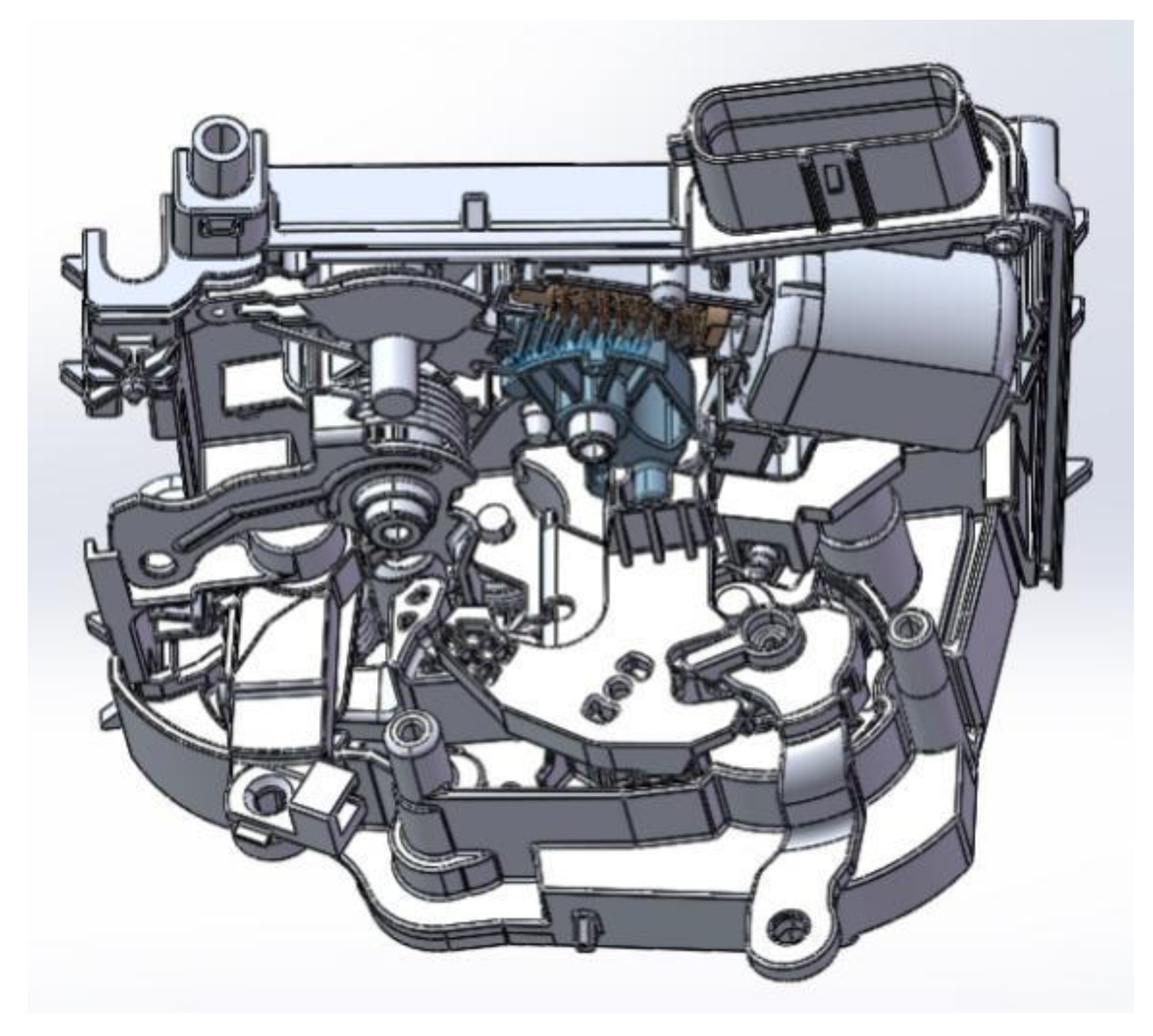
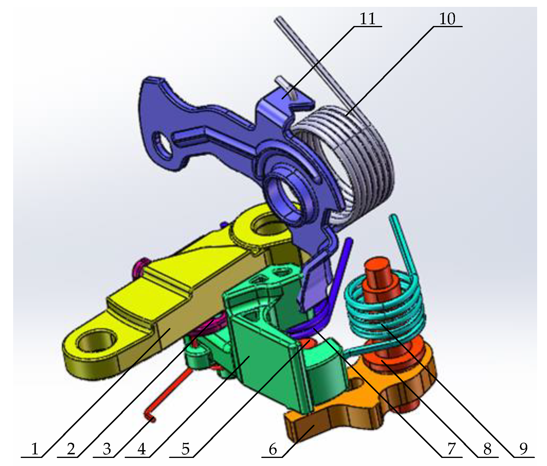
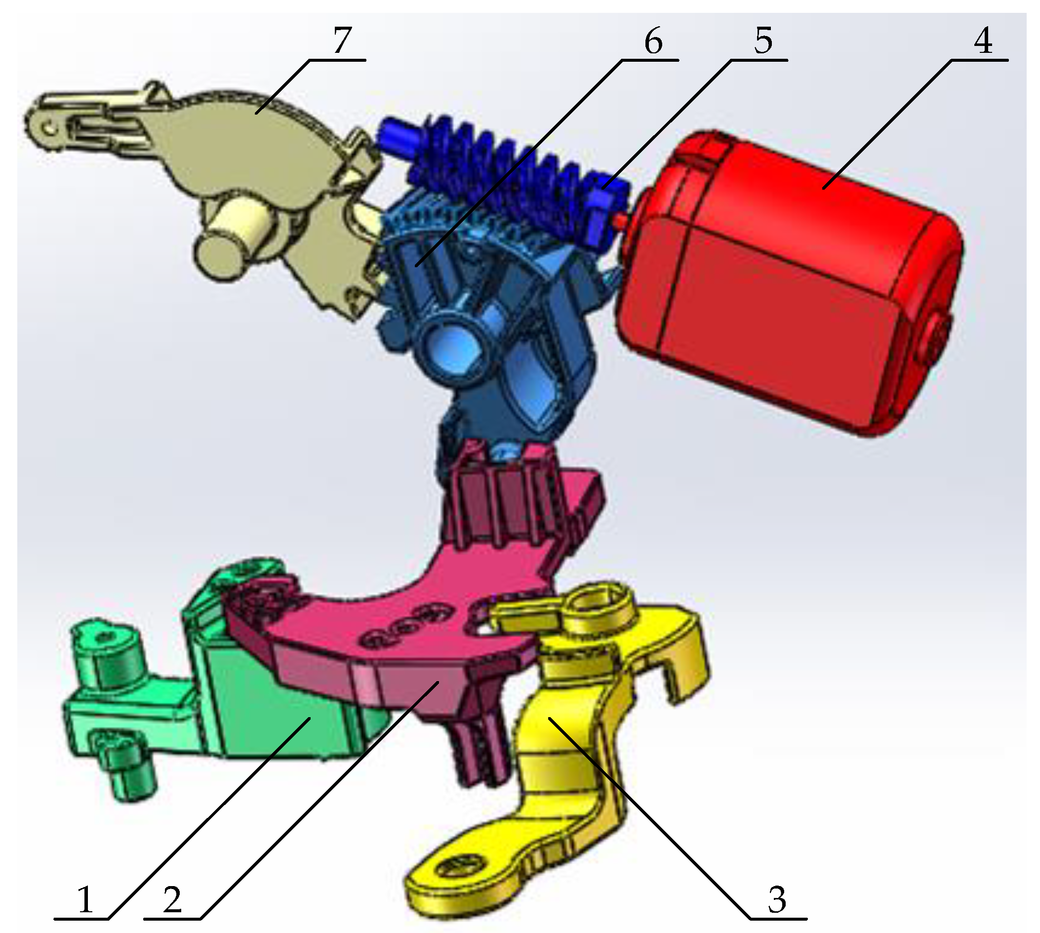
2.1. Working Mechanism of a Light Truck Door Latch

The internal structure model of a light truck door latch is shown in Figure 1. The latch can realize the door holding function through the holding mechanism, realize the opening function of the vehicle door through the inner and outer opening mechanism, and realize the locking and unlocking functions of the vehicle door lock through the locking mechanism. The three-dimensional models of the holding mechanism, the inner and outer opening mechanism, and the locking mechanism are shown in Figure 2, Figure 3 and Figure 4, respectively.
The holding mechanisms of the door latch are mainly composed of metal parts, including the striker, pawl, pawl riveting shaft, bottom plate, fork-bolt, auxiliary bottom plate, and fork-bolt riveting shaft. When the fork-bolt and the pawl are in the fully latched position, as shown in Figure 2, the striker can be locked in the latch and cannot be disengaged, thus realizing the holding function of the door lock.
The inner and outer opening mechanisms of the door lock body are mainly composed of an outside opening toggle arm, opening connect arm, lock return torsion spring, pawl connect arm, pawl connect shaft, pawl, opening connect arm torsion spring, pawl riveting shaft, pawl torsion spring, inside opening toggle arm torsion spring, and inside opening toggle arm. Under the action of manpower, the inner handle drives the inner opening toggle arm to rotate through the pull wire so that the pawl connect arm hooks the pawl connect shaft and drives the pawl to rotate, unlocking the latch. The outer handle drives the outer opening toggle arm to rotate through the pull lever so that the pawl connect arm hooks the pawl connect shaft and drives the pawl to rotate, unlocking the latch.
The locking mechanisms of the door lock body are mainly composed of the pawl connect arm, locking connect arm, key locking toggle arm, motor, worm, locking gear, and inside locking toggle arm. The inside locking toggle arm, the motor, and the key locking toggle arm, respectively, drive the locking connect arm to rotate so that the pawl connect arm and the pawl connect shaft are separated, the kinematic chain is interrupted, and the locking functions of inside locking, remote locking, and key locking can be realized.

2.2. Light Truck Door Lock Performance Requirements

According to the American SAE standard SAEJ839v002, the basic requirements for the mechanical properties of the car door latch are as shown below.
(1)
Longitudinal Load—An automotive door latch and striker assembly, when tested as described under test procedures, must be able to withstand an ultimate longitudinal load of 11,000 N when in the fully latched position and 4450 N when in the secondary latched position.
(2)
Transverse Load—An automotive door latch and striker assembly, when tested as described under test procedures, must be able to withstand an ultimate transverse load of 8900 N when in the fully latched position and 4450 N when in the secondary latched position.
(3)
Inertia Load—An automotive door latch, when contained in the door latch system (including the door latch, striker assembly, outside handle, key cylinder, and any connecting mechanisms), and in the fully latched position, when evaluated by calculation, must remain in the fully latched position when subjected to an inertia load of 30g in any direction.
In this study, when analyzing the inertia load resistance of the light truck door latch, the following requirements were carried out:
When the door lock is in the fully latched position, it can withstand an inertia load of 60 g of acceleration and 30 ms of action time in any direction and can maintain the fully latched position.

2.3. Analysis of Unlocking Causes of Light Truck Door Latch under Side Impact Load

According to the holding mechanism of the light truck door latch, the following conditions will cause the latch to disengage from the striker:
(1)
The structures of the fork-bolt, pawl, bottom plate, auxiliary bottom plate, and riveting shaft are greatly deformed or even damaged, which makes the holding function invalid.
(2)
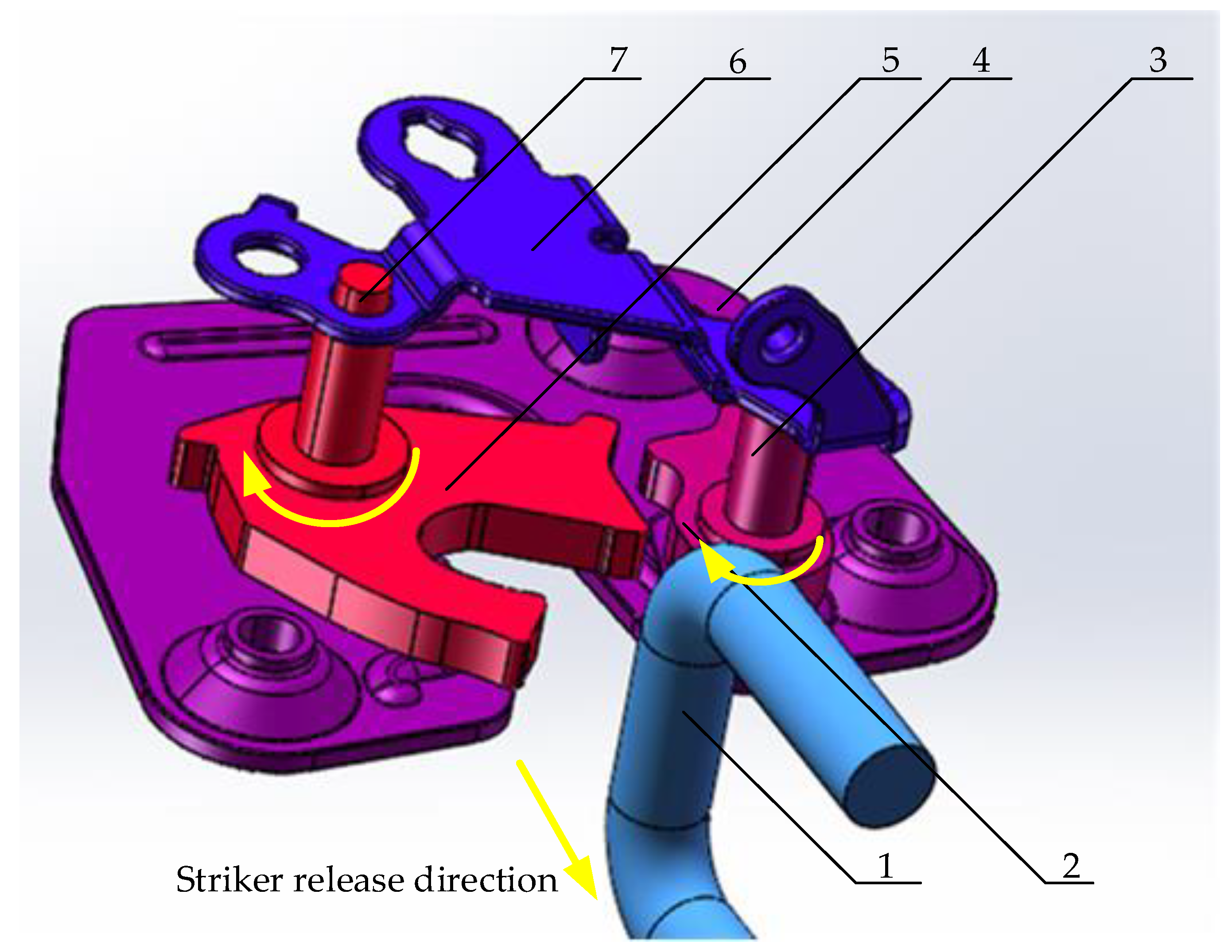
The pawl rotates in the unlocking direction until it cannot block the rotation of the fork-bolt so that the fork-bolt cannot lock the striker, and the latch is unlocked and disengaged from the striker, as shown in Figure 5.
Since the total mass of the light truck door lock body is about 300 g, under the action of a 60 g impact load, the inertial force of the entire latch is about 180 N and the generated stress is far less than the strength limit of the material. Therefore, the possibility of structural deformation or even damage was not considered in the inertia load resistance analysis. It was only necessary to study the inertia load resistance of the latch and analyze the rotation of the pawl. When the door is closed, the pawl is held in the fully latched position by the preload torque of the pawl torsion spring. In the normal opening condition, the opening force acts on the outside handle to overcome the torque of the outside handle torsion spring so that the counterweight mechanism rotates. The counterweight mechanism exerts a pulling force on the latch through the lever so that the outside opening toggle arm drives the pawl connect arm to move through the opening connect arm. When the pawl connect arm hooks the pawl connect shaft, it drives the pawl to rotate to unlock the latch. When subjected to a 60 g side inertia load, under the action of inertial force, the outside handle and the parts of the outer opening kinematic chain of the lock will generate a resultant moment that overcomes the preload torque of the torsion spring of the pawl, and the pawl will rotate. As a result, the latch is abnormally unlocked. Friction only makes the latch more difficult to unlock, so it can be ignored in calculations and simulations.

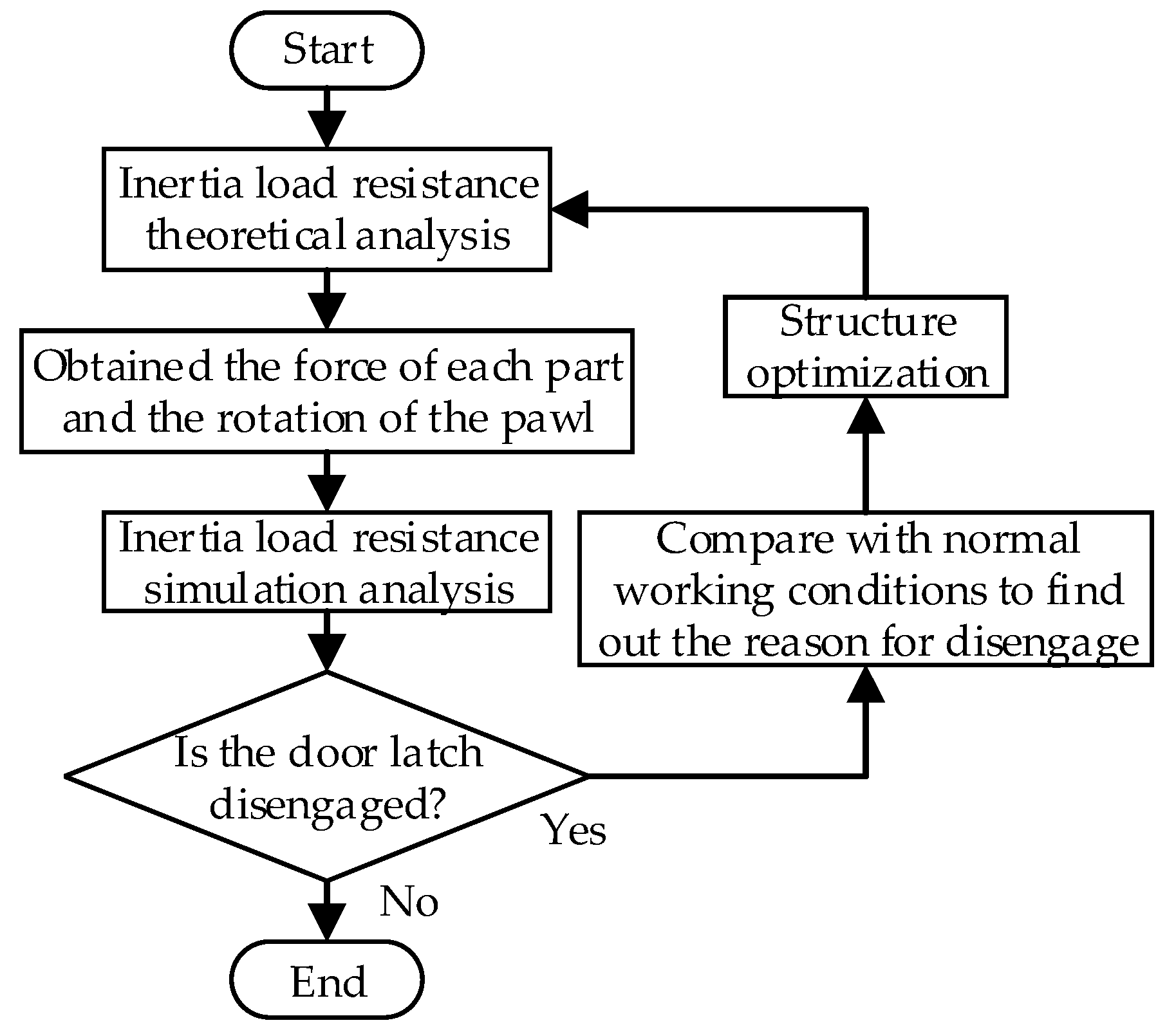
2.4. Light Truck Door Latch Inertia Load Resistance Analysis Process

In this study, a light truck door latch system was subjected to a 60 g side impact load as an example to study the inertia load resistance analysis process of the door latch. Firstly, the theoretical calculation of inertia load resistance was carried out on the latch and the force of each part on the outside opening kinematic chain of the latch and the rotation of the pawl were analyzed. Secondly, the inertia load resistance simulation analysis of the outside opening kinematic chain model of the lock was carried out to verify the reliability of the theoretical calculation results. Thirdly, if the theoretical calculation result was that the latch will be unlocked under the action of a 60 g side impact load, the force of each part in the theoretical calculation process was compared with the normal opening condition of the latch to provide a basis for the optimization of the latch structure. Finally, a theoretical calculation and simulation analysis of the inertia load resistance were carried out on the latch after the structure optimization, and the latch structure that met the requirements of the inertia load resistance was obtained. The specific analysis process is shown in Figure 6.

3. Theoretical Calculation of Inertia Load Resistance of Light Truck Door Latch

3.1. Torque Calculation of the Torsion Spring of a Light Truck Door Latch

For the torque calculation of the torsion spring, refer to the Spring Design Manual [24]. The torque calculation formula of the torsion spring is as follows:
T = d 4 × E 3667 × D × N + 389 × ( A + B ) × Φ
where d is the wire diameter of the torsion spring, E is Young’s modulus of elasticity of the torsion spring material, D is the mean coil diameter of the torsion spring, N is the total number of coils of the torsion spring, A is the length of the stationary side of the torsion spring, B is the length of the moving side of the torsion spring, and Φ is the torsion angle of the torsion spring.
The torsion spring parameters involved in the theoretical calculation are shown in Table 1.
In the theoretical calculation of inertia load resistance, the torque value is the average value of the preload torque and the torque at the maximum stroke. We substituted the parameters in Table 1 into Formula (1) and calculated the torque of torsion spring as shown in Table 2.

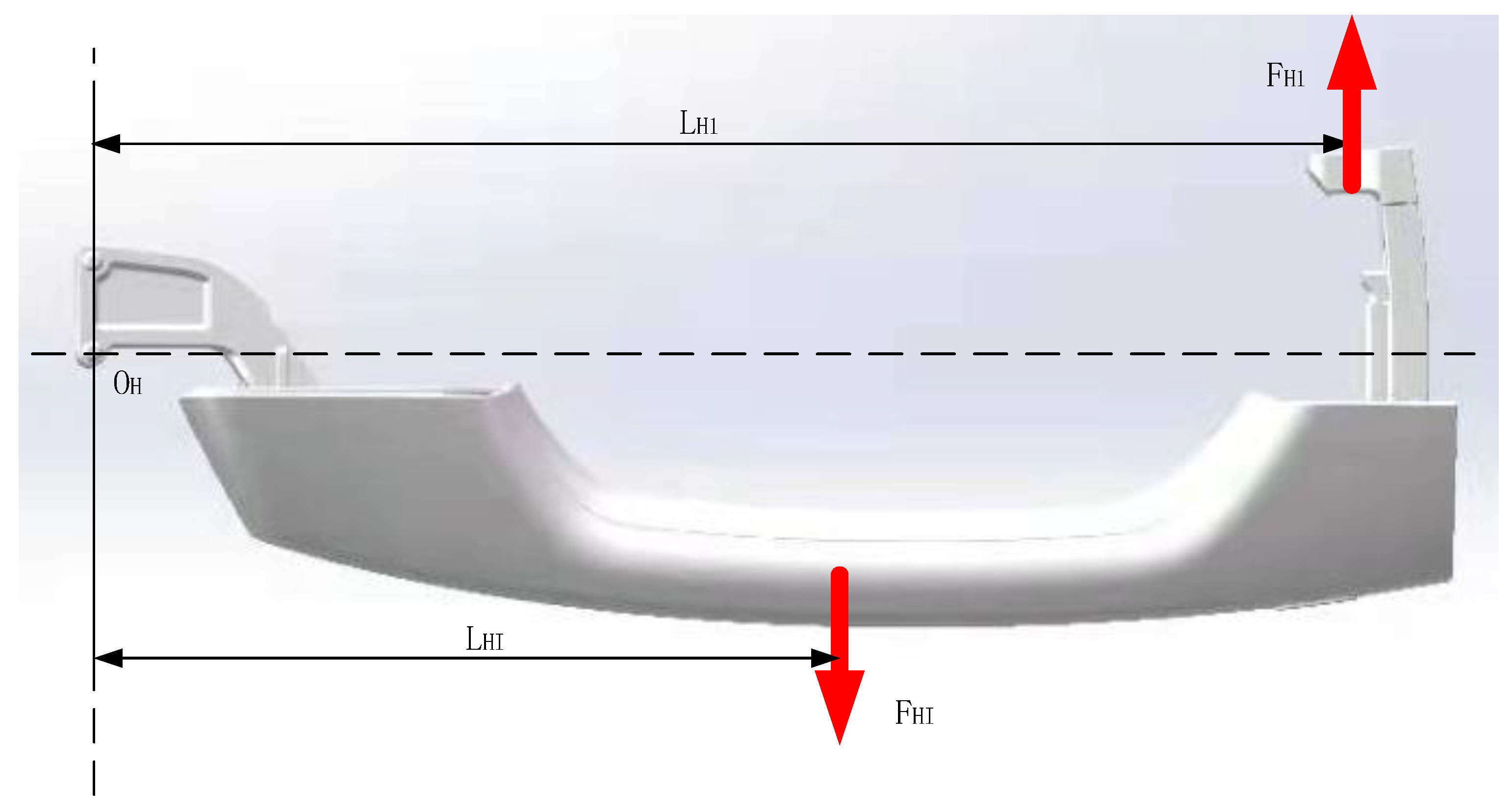
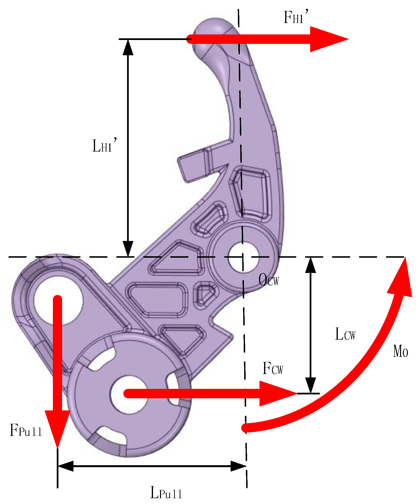
3.2. Calculation of Force of Light Truck Door Latch Outside Handle

According to the movement of each part, they are divided into moving parts and rotating parts, and Formulas (2) and (3) can be obtained by analyzing the force conditions of the parts.
F i = 0
F i L i = M
The three-dimensional model of the light truck door latch system outside handle structure is shown in Figure 7.
The force of the outside handle is shown in Figure 8. OH is the handle rotation center, FHI is the handle inertial force, and FH1 is the thrust of the counterweight mechanism on the handle.
The force of the counterweight mechanism of the outside handle is shown in Figure 9. OCW is the rotation center of the counterweight mechanism, FCW is the inertial force of the counterweight block, and Fpull is the pulling force of the counterweight mechanism by the lever, and the inertial force of the counterweight mechanism itself can be ignored.
The parameters of the parts involved in the theoretical calculation are shown in Table 3.
The size parameters of the outside handle are shown in Table 4.
The calculation formula can be obtained as follows:
( F H I F H 1 F C W F P u l l ) ( L H I 0 L H 1 L H 1 0 L C W 0 L P u l l ) = ( 0 M 0 )
Obtained: F P u l l = 22.08   N .

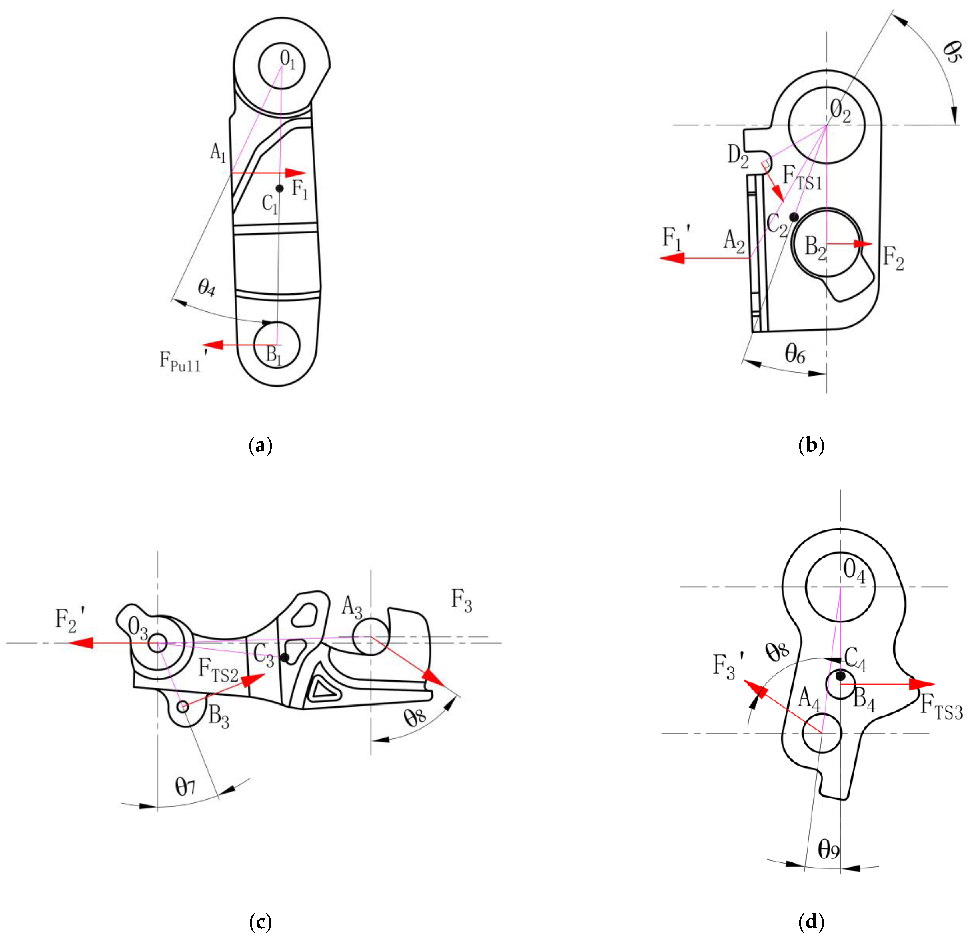
3.3. Force Calculation of Parts of Light Truck Door Latch Outside Opening Kinematic Chain

After the initial pulling force is obtained, each part of the outside opening kinematic chain of the latch was analyzed separately. The schematic diagrams of the force of the parts are shown in Figure 10, and the size parameters of the parts are shown in Table 5, where FPull, F1, F2, and F3 are the interaction forces between the lever and the outside opening toggle arm, the outside opening toggle arm and the opening connect arm, the opening connect arm and the pawl connect arm, and the pawl connect arm and the pawl respectively, FTS1, FTS2, and FTS3 are the acting forces of the opening connect arm torsion spring, the lock return torsion spring, and the pawl torsion spring, respectively, and O1, O2, O3, and O4 are the rotation centers of each part.
According to the force situation in Figure 10, the moment balance analysis was performed on each part, the force analysis on the pawl connect arm was performed, and the force and moment balance equations can be listed.
( F P u l l F C 1 F 1 F C 2 F 2 F C 3 F T S 2 F 3 F C 4 ) ( l O 1 B 1 0 0 0 0 0 l O 1 C 1 cos θ 1 0 0 0 0 0 l O 1 A 1 cos θ 4 - l O 2 A 2 cos ( 90 ° - θ 5 ) 0 0 0 0 0 l O 2 C 2 cos ( θ 6 + θ 2 ) 0 0 0 0 0 l O 2 B 2 - 1 0 0 0 0 0 0 1 0 0 0 0 cos θ 7 sin θ 7 - l O 3 B 3 0 0 0 sin θ 8 cos θ 8 0 - l O 4 A 4 sin ( θ 8 + θ 9 ) 0 0 0 0 0 l O 4 C 4 sin θ 3 ) = ( 0 M 1 0 0 M 2 M T )
where θ1 represents the rotation angle of the outside open toggle arm affected by the inertial force; θ2 represents the rotation angle of the open connect arm affected by the inertial force; θ3 represents the rotation angle of the pawl connect arm affected by the inertial force. When θ1 = θ2 = θ3, it means that the pawl does not rotate; when θ1, θ2, and θ3 are not 0, it means that the pawl has rotated, and its specific value is related to the maximum torsion angle of the torsion spring. In the calculation of the resistance to inertia, half of the maximum stroke angle was taken.
The results of the calculations are shown in Table 6. Under the side impact load of 60 g, the torsion force on the pawl along the opening direction was M T = 826.66 N·mm, which exceeded the torsion force of the pawl torsion spring by 139.55 N·mm. In summary, the door lock will disengage under a 60 g side impact load.
According to the above ideas, it can also be calculated that a minimum pulling force of Fpull = 6.02 N is required to unlock the latch in normal opening conditions. In the above calculation, Fpull = 22.08 N was generated by the outside handle to the latch under the side impact load of 60 g, indicating that the main reason that may lead to the unlocking of the door latch is that the structural design of the outside handle is unreasonable. If the structure of the outside handle is optimized, for example, by reducing the mass of the handle, increasing the mass of the counterweight, or increasing the torque of the outside handle torsion spring, etc., the F-pull of the outside handle to the latch due to inertia can be reduced to less than 6.02 N so that the door latch system can meet the inertia load resistance requirements.

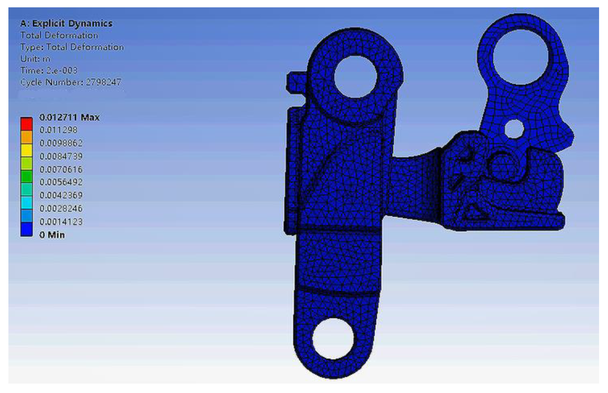
4. Simulation Analysis of Inertia Load Resistance of Light Truck Door Latch

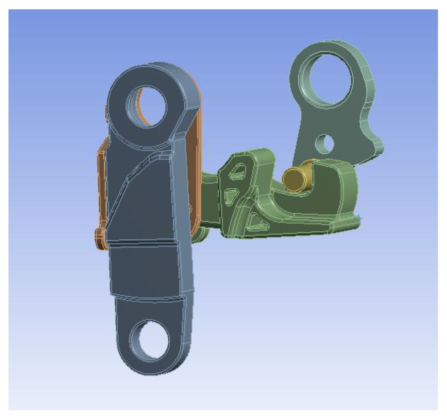
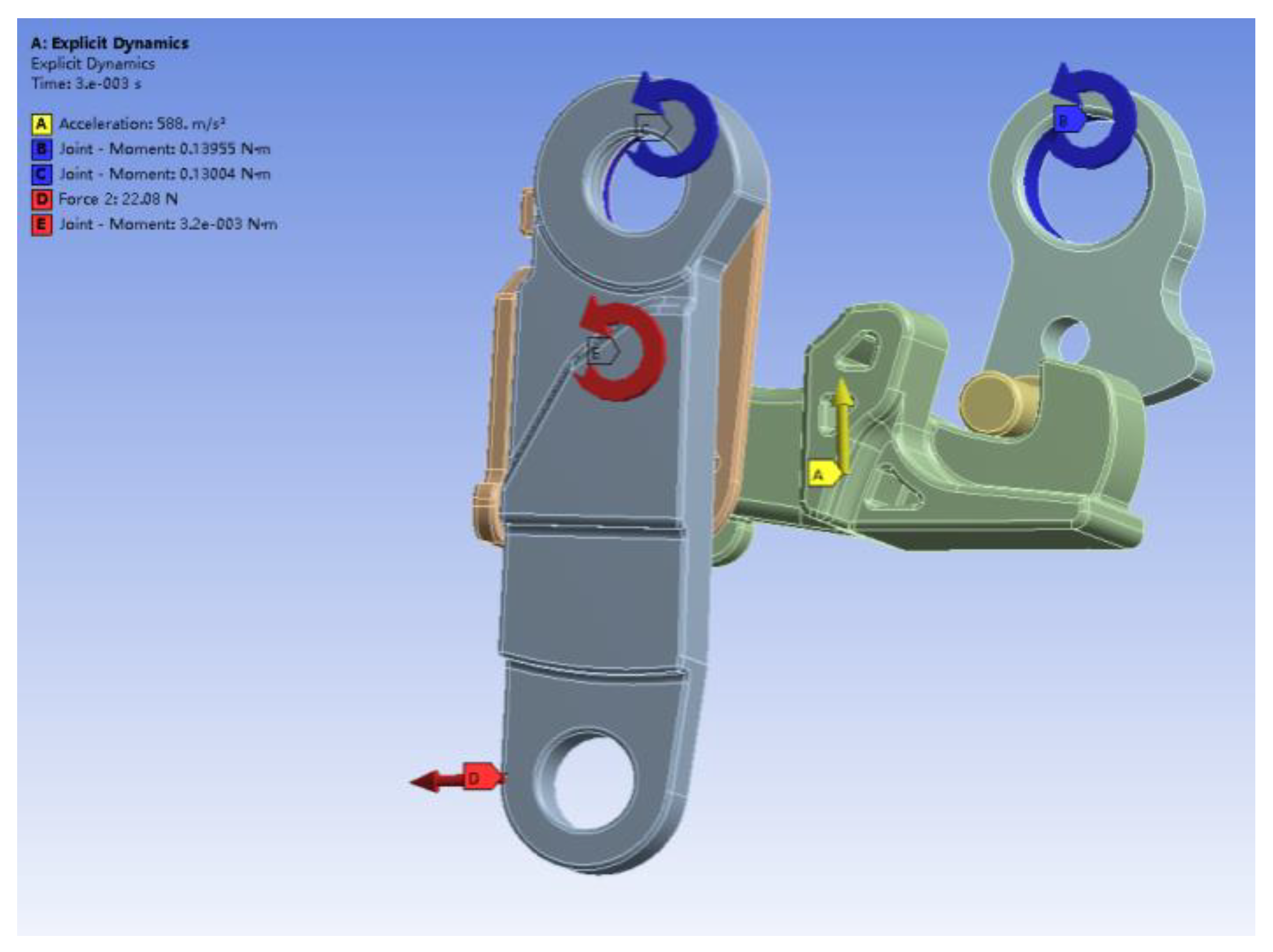
4.1. Inertia Load Resistance Simulation Model of Light Truck Door Latch

The simulation platform configuration for the inertia load resistance simulation in this study was: processor—Intel(R) Xeon(R) CPU E3-1231 v3 @ 3.40 GHz, memory size—16.0 GB, operating system—win10 64-bit.
In this study, the motion simulation analysis of the latch structure of the door latch under 60 g side impact load was carried out with the finite element simulation analysis software. The shell, fixed shaft, and other parts that do not move due to inertial force were omitted, and the torsion spring was replaced by equivalent torque. The simplified model is shown in Figure 11.
We set the material of the outside opening toggle arm and the pawl connect arm as Polyamide 6 + 30% Glass Fiber, the material of the pawl as 35CrMo, and the material of the opening connect arm and the pawl connect shaft to be DC01. The material parameters are shown in Table 7.
The imported 3D model was divided into meshes, the meshing method was Automatic, and the mesh size was set to 1 mm. A total of 15,880 mesh nodes and 61,820 mesh elements were generated, with a mesh quality of 0.78, as shown in Figure 12.
We set ground rotation constraints for the pawl, outside opening toggle arm, and opening connect arm, respectively, and set rotation constraints between the pawl connect arm and the opening connect arm. The connection between the pawl connect shaft and the pawl was set to bind. The friction made it more difficult to disengage, which could be ignored in the theoretical calculation and simulation. The outside opening toggle arm and the opening connect arm and the pawl connect arm and the pawl connect shaft were respectively provided with frictionless contact. We set fixed constraints on the pawl stop and added a pawl torsion spring, an outside opening torsion spring, and a lock return torsion spring moment. The side impact load was constant at 588 m/s2, and the opening force Fpull was constant at 22.08 N, which lasted from 0 ms to 30 ms. The result is shown in Figure 13.

4.2. Simulation Analysis Results of Inertia Load Resistance of Light Truck Door Latch

In this study, the Solution module was used to solve the simulation model of the door latch, and the estimated remaining time required to complete the simulation calculation can be viewed in the Solution Information. If the side impact load of 30 ms was fully loaded, the time required to obtain the simulation results was expected to exceed 3000 h. Since it was only necessary to observe whether the pawl would be rotated by the pawl connect arm in the simulation results on the premise that the pawl connect arm can contact the pawl connect shaft, the loading time of the side impact load was modified to 2 ms. The simulation results after about 80 h of computing are shown in Figure 14 and Figure 15.
It can be seen that under the 60 g side impact load, the outside opening toggle arm at the beginning drives the pawl connect arm to move, but it has not contacted the pawl connect shaft. It continues to move until contact and drives the pawl to rotate so that the latch is unlocked. The maximum deformation is 12.7 mm at the bottom of the outside opening toggle arm. The theoretical calculation results show that under the 60 g side impact load, the combined torque generated by the external force on the pawl overcame the torque of the pawl torsion spring so that the pawl would rotate and the latch would disengage. The simulation results are in agreement with the theoretical calculation results.

5. Structural Optimization and Verification of Light Truck Door Latch System

Comparing the disengage condition of the latch under a 60 g side impact load with normal opening conditions, it was found that the main reason for the disengagement was that the opening force input Fpull by the handle to the latch was too large. Therefore, the criterion of structural optimization was to reduce the Fpull by optimizing the handle structure, which can be reduced by reducing the handle mass, increasing the mass of the counterweight block, increasing the torque of the torsion spring of the outer open handle, or using a mixture of these three methods. Thus, the size of the latch and the design itself remained unchanged. In this study, after calculation, the method of increasing the weight of the counterweight block was adopted to optimize the size parameters of the counterweight block from a 6.5 mm radius and 13 mm height to an 8.5 mm radius and 14.95 mm height. The counterweight block could be increased from 70 g to 137.62 g, resulting in a reduction in the Fpull from 22.08 N to 5.5 N. The Fpull was modified to 5.5 N, and the pawl connect arm could not contact the pawl connect shaft in 2 ms, so the loading time of the side impact load was modified to 4 ms. The simulation calculation was performed again. The simulation results after about 120 h are shown in Figure 16. It can be seen that the outside opening toggle arm drove the movement of the pawl connect arm, and the pawl did not rotate after contacting the pawl connect shaft. The maximum deformation was 8.3 mm at the bottom of the outside opening toggle arm. This shows that if the outside handle is optimized according to the theoretical calculation results, the door latch system meets the inertia load resistance requirements.
The simulation results of inertia load resistance are consistent with the theoretical calculation results, which shows the reliability of the theoretical calculation results. Since the results obtained by the inertia load resistance simulation analysis are basically consistent with the inertia load resistance theoretical calculation results and the inertia load resistance simulation takes a lot of time, after the first inertia load resistance simulation analysis and verification, the inertia load resistance simulation step can be omitted in the subsequent structural optimization process.

6. Conclusions

In this paper, an inertia load resistance analysis method for a light truck door latch is proposed. Firstly, the reasons for the door latch disengagement were analyzed, the theoretical calculation was carried out, and the reliability of the theoretical calculation results was verified by inertial simulation. Then, we compared and analyzed the theoretical calculation results with the normal opening conditions to find out the reasons for the unlocking of the latch, and provided a basis for the structural optimization design, which can accurately design and optimize a latch structure of a light truck door latch that meets the requirements of the inertia load resistance in the early stage of design and development, which shortens the development cycle and saves development costs.

Author Contributions

Conceptualization, J.H. and L.X.; methodology, L.X.; software, L.X. and Y.S.; validation, L.X., S.G. and Y.S.; formal analysis, J.H.; investigation, J.H.; resources, G.L.; data curation, L.X.; writing—original draft preparation, L.X.; writing—review and editing, J.H. and G.L.; visualization, L.X.; project administration, J.H. All authors have read and agreed to the published version of the manuscript.

Funding

This research received no external funding.

Institutional Review Board Statement

Not applicable.

Informed Consent Statement

Not applicable.

Conflicts of Interest

The authors declare no conflict of interest.

References

  1. Road Traffic Injuries. Available online: https://www.who.int/news-room/fact-sheets/detail/road-traffic-injuries (accessed on 7 March 2022).
  2. Qianghong, L.; Sanhong, L.; Lizhi, L. Calculation Method Study on Inertial Load Resistance of Motor Vehicles’ Door Locks. Automob. Technol. 2012, 10, 4–6. [Google Scholar]
  3. Baohua, D.; Guangxue, D. The design analysis and application of door handle anti-collision capability. Automob. Appl. Technol. 2017, 16, 120–123. [Google Scholar]
  4. Yunguang, J.; Guangxue, D.; Wei, Z. The Design and calculation of inertia for latch system of automobile. Automob. Appl. Technol. 2017, 8, 123–126. [Google Scholar]
  5. Guangxue, D.; Xin, W. (Eds.) The Simulation and Optimization for Opening Mechanism of Automobile Side Door Lock Crash Worthiness. In Proceedings of the Annual Meeting of the Society of Automotive Engineers of China (4), Shanghai, China, 22 October 2019. [Google Scholar]
  6. Chiang, J.Y.; Barber, G.C. Operating effort and related statistical tolerance analyses of automotive latching mechanisms. Int. J. Mater. Prod. Tec. 2002, 17, 353–367. [Google Scholar] [CrossRef]
  7. Xueming, H.; Lili, S.; Changjiang, X. Failure Mode Analysis and Optimal Design of an Automobile Door Lock. Mach. Des. Res. 2016, 32, 129–133. [Google Scholar]
  8. Lee, Y.H.; Lee, T.H.; Jeong, H.S.; Yoon, G.H.; Kim, W.H.; Jung, B.D.; Lee, J.B.; Kim, D.B.; Shin, J.Y. Calculation Formula for Operating Force of Vehicle Door Latch: Part 1—Catch, Pawl and Release Lever. Trans. Korean Soc. Noise Vib. Eng. 2020, 30, 37–44. [Google Scholar] [CrossRef]
  9. Lee, Y.H.; Lee, T.H.; Choi, S.B.; Jeong, H.S.; Yoon, G.H.; Kim, W.H.; Jung, B.D.; Lee, J.B.; Kim, D.B.; Shin, J.Y. Calculation Formula for Operating Force of Vehicle Door Latch: Part 2—OS/IS Lever and Total Force Analysis. Trans. Korean Soc. Noise Vib. Eng. 2020, 30, 45–51. [Google Scholar] [CrossRef]
  10. Wu, X.C.; Tian, G.H.; Liu, J. Research on Crashworthiness of Car Bumper System. In Proceedings of the 3rd International Conference on Advanced Engineering Materials and Technology (AEMT 2013), Zhangjiajie, China, 11–12 May 2013. [Google Scholar]
  11. Fei, L.; Shiguo, E.; Xin, Q. CAE Optimization for Rear Door Opening in MDB Side Impact Test for a Vehicle. J. Automot. Saf. Energy 2013, 4, 130–135. [Google Scholar]
  12. Fang, S. Simulation and Research of Child Restraint System in Rear End Impact and Side Impact. Master’s Thesis, South China University of Technology, Guangzhou, China, January 2016. [Google Scholar]
  13. Yeom, K.; Ahn, B. A study of side impact test assessment using the side system simulation model. KSAE 2018, 26, 490–495. [Google Scholar] [CrossRef]
  14. Long, C.R.; Yuen, S.; Nurick, G.N. Analysis of a car door subjected to side pole impact. Lat. Am. J. Sol. Struct. 2019, 16, e226. [Google Scholar] [CrossRef]
  15. Xiaojie, H.; Lubin, H.; Mingyuan, W.; Xiaobo, H.; Qiansheng, W.; Zhe, L.; Yong, C.; Yong, H.; Jinliang, D. Analysis of Multi-mode Inertial Mechanism of Automotive Door Lock Based on ADAMS. In Proceedings of the International Conference on Robotics, Intelligent Control and Artificial Intelligence (RICAI), Shanghai, China, 20–22 September 2019. [Google Scholar]
  16. Maria, M.A.; Daniel, I.; Victor-Costin, D.; Cornelia, S. Lateral Impact Behavior Study of a Car Door. In Proceedings of the 4th International Congress of Automotive and Transport Engineering (AMMA), Cluj-Napoca, Romania, 17–19 October 2018. [Google Scholar]
  17. Hequan, W.; Shijie, K.; Hanbin, H. Research on Application of Electric Vehicle Collision Based on Reliability Optimization Design Method. Int. J. Comp. Methods-Sing. 2019, 16, 1950034. [Google Scholar]
  18. More, K.C.; Patil, G.M.; Belkhede, A.A. Design and analysis of side door intrusion beam for automotive safety. Thin-Wall. Struct. 2020, 153, 106788. [Google Scholar] [CrossRef]
  19. Weiwei, W.; Shijuan, D.; Wanzhong, Z.; Chunyan, W.; Tao, M.; Qingyun, C. Reliability-based optimization of a novel negative Poisson’s ratio door anti-collision beam under side impact. Thin-Wall. Struct. 2020, 154, 106863. [Google Scholar]
  20. Kim, J.Y.; Choi, S.H. Study on the optimization design and impact experiment of side door for impact beam in the vehicle side door. Tribol. Lubr. 2015, 31, 13–20. [Google Scholar]
  21. Ganessh, T.S.; Bansode, P.; Revankar, V.; Kumar, S. Vehicle performance evaluation in side impact (MDB) using ES-II dummy. In Proceedings of the 1st International Conference on Advances in Metallurgy, Materials and Manufacturing, Salem, India, 6–8 March 2017. [Google Scholar]
  22. Chuanxing, L.; Gaojun, C.; Chengjing, Z.; Yi, X. Research on the Issue of Rear Door Opening during Side Impact. In Proceedings of the 2020 China Society of Automotive Engineering Annual Conference and Exhibition, Shanghai, China, 27 December 2020. [Google Scholar]
  23. Chuanxing, L.; Gaojun, C.; Wanli, L.; Yi, X.; Chengjing, Z. Research and Optimization of Deformation Mode of Outer Door Metal under Side Impact Conditions. In Proceedings of the 2021 China Society of Automotive Engineering Annual Conference and Exhibition, Shanghai, China, 19 December 2021. [Google Scholar]
  24. Cengxiang, W.; Xianying, W.; Xiangzhi, L. Spring Design Manual, 1st ed.; Shanghai Scientific and Technical Literature Publishing House: Shanghai, China, 1986; pp. 259–260. [Google Scholar]
Figure 1. The internal structure model of a light truck door latch.
Applsci 12 04171 g001
Figure 2. The holding mechanism model. (1) Striker, (2) pawl, (3) pawl riveting shaft, (4) bottom plate, (5) fork-bolt, (6) auxiliary bottom plate, (7) fork-bolt riveting shaft.
Applsci 12 04171 g002
Figure 3. The inner and outer opening mechanism model. (1) Outside opening toggle arm, (2) opening connect arm, (3) lock return torsion spring, (4) pawl connect arm, (5) pawl connect shaft, (6) pawl, (7) opening connect arm torsion spring, (8) pawl riveting shaft, (9) pawl torsion spring, (10) inside opening toggle arm torsion spring, (11) inside opening toggle arm.
Applsci 12 04171 g003
Figure 4. The locking mechanism model. (1) Pawl connect arm, (2) locking connect arm, (3) key locking toggle arm, (4) motor, (5) worm, (6) locking gear, (7) inside locking toggle arm.
Applsci 12 04171 g004
Figure 5. Schematic diagram of the disengagement of the latch and the striker. (1) Striker, (2) pawl, (3) pawl riveting shaft, (4) bottom plate, (5) fork-bolt, (6) auxiliary bottom plate, (7) fork-bolt riveting shaft.
Applsci 12 04171 g005
Figure 6. The flow chart of the inertia load resistance analysis of the latch of the light truck door latch.
Applsci 12 04171 g006
Figure 7. Outside handle structure. (1) Handle, (2) counterweight, (3) counterweight mechanism, (4) outside handle torsion spring, (5) lever.
Applsci 12 04171 g007
Figure 8. Schematic diagram of handle force.
Applsci 12 04171 g008
Figure 9. Schematic diagram of counterweight mechanism.
Applsci 12 04171 g009
Figure 10. The schematic diagram of the force of the parts of the outside opening kinematic chain of the latch. (a) Outside opening toggle arm, (b) opening connect arm, (c) pawl connect arm, (d) pawl.
Applsci 12 04171 g010
Figure 11. Simplified door latch simulation model.
Applsci 12 04171 g011
Figure 12. Simulation model meshing results.
Applsci 12 04171 g012
Figure 13. Overall loads and restraints.
Applsci 12 04171 g013
Figure 14. The initial state of the door latch simulation movement.
Applsci 12 04171 g014
Figure 15. The end state of the door latch simulation movement.
Applsci 12 04171 g015
Figure 16. 5.5 N simulation results of motion end state.
Applsci 12 04171 g016
Table 1. Torsion spring parameter table.
NameWire Diameter/mmMean Coil Diameter/mmTotal Number of CoilsMaterialArm Length 1
/mm
Arm Length 2
/mm
Outside handle torsion spring1.711.58.2565 Mn1212
Opening connect arm torsion spring1.2125.465 Mn235.6
Lock return torsion spring0.873.5565 Mn16.36.1
Pawl torsion spring1.210.84.2565 Mn178.4
Table 2. Torsion of torsion spring.
NamePreload Torque/(N·mm)Inertia Load Resistance Calculation Torque/(N·mm)Torque When Fully Disengaged/(N·mm)
Outside handle torsion spring/M0341.92
Outside open torsion spring/M1113.79130.04146.30
Lock back torsion spring/M232.00
Pawl torsion spring/M3124.80139.55154.30
Table 3. Parts parameters.
NameVolume/mm3Density (kg/m3)Mass/g
Outside handle--139
Outside handle counterweight-786070
Outside open toggle arm23551370-
Opening connect arm5407850-
Pawl connect arm2817.51370-
Pawl9707850-
Table 4. The size parameters of the outside handle.
ArmLength/(mm)ArmLength/(mm)
LHI123.37LH1208.50
LH1′26.50LCW10.00
LPull24.00
Table 5. Size parameters of outside opening kinematic chain parts.
Distance between Two PointsLength/(mm)Distance between Two PointsLength/(mm)
LO1A115.50LO1C116.00
LO1B136.00LO2A216.50
LO2C210.50LO2C28.00
LO2B212.75LO3B37.50
LO3A323.50LO3C314.00
LO4A415.00LO4B410.00
LO4C49.15
Table 6. The theoretical calculation results of the inertia load resistance of the door latch.
Working ConditionForce/TorqueCalculation ResultsForceCalculation Results
60 g side impact loadFPull22.08 NF156.26 N
F252.11 NF356.20 N
MT826.66 N·mm
Normal opening conditionFPull6.02 NF115.10 N
F25.98 NF310.66 N
MT139.82 N·mm
Table 7. The material parameters.
MaterialDensity/(kg/m3)Young’s Modulus/(MPa)Poisson’s Ratio
PA6 + 30%GF13701 × 1050.35
35CrMo79002.13 × 1050.286
DC0178502.06 × 1050.32
Publisher’s Note: MDPI stays neutral with regard to jurisdictional claims in published maps and institutional affiliations.

