1. Introduction
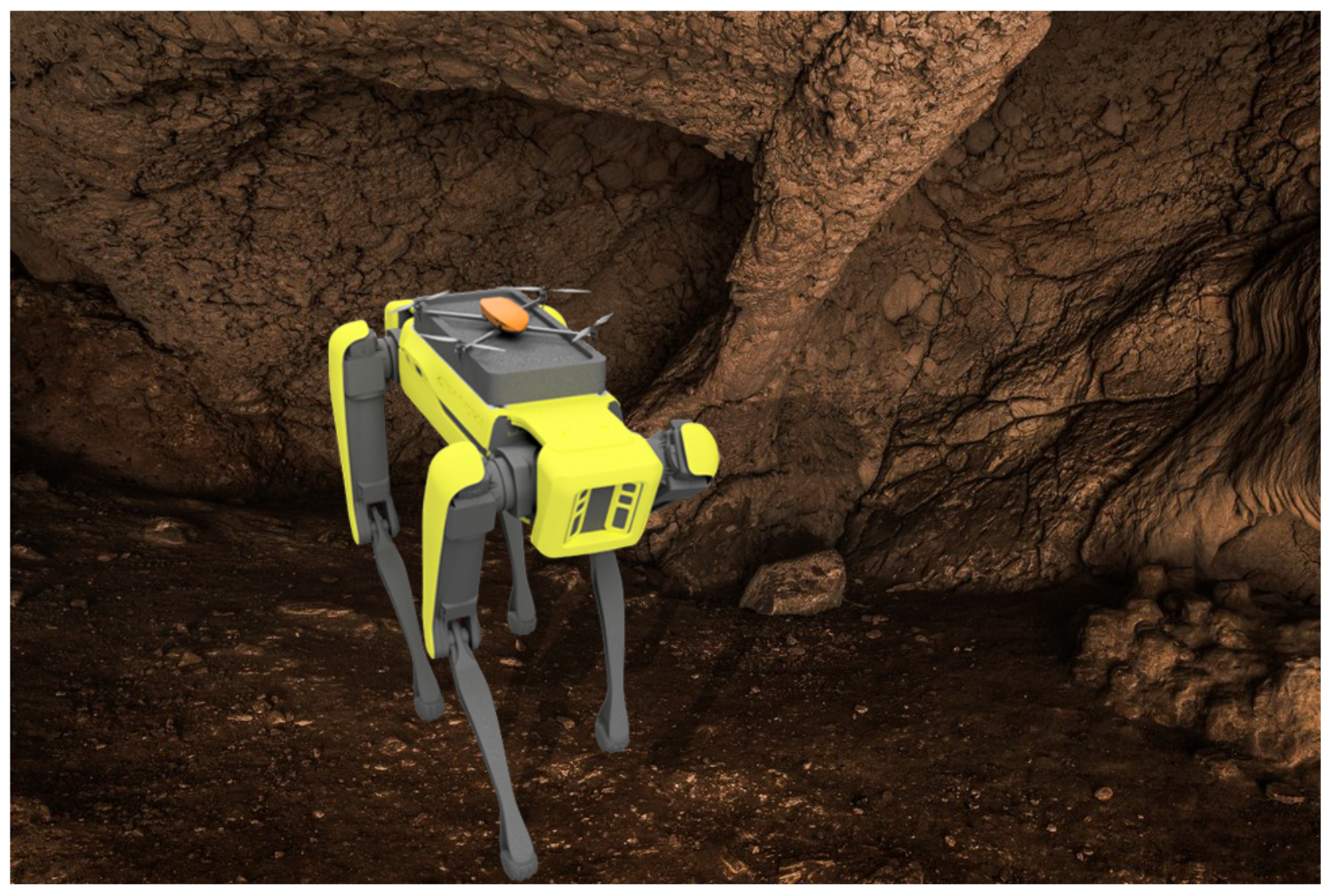
Over the past few years, autonomous robots have experienced their utilization in more real-world applications, mainly because of their ability to navigate in environments with minimal human supervision, which has increased their use in various industrial sectors including energy, construction, healthcare, delivery, and space. However, with new robotic applications emerge new challenges in which there is a need for a collaborative operation in exploration missions and for sharing common information about the operating environment among different robots or robot modalities, in which, for example, a ground robot is carrying an aerial one. Recent advancements in the field of autonomous robots are fostering the development of robotic modalities for collaborative missions, where one bigger robot is capable of carrying deploying a smaller one autonomously, as shown in
Figure 1. This technology can be applied in scenarios such as exploration [
1], infrastructure inspection [
2], search and rescue [
3], etc. Recently, in the autonomous space mission, NASA demonstrated the unification of the Mars Rover Perseverance with a small robotic helicopter, Ingenuity [
4], while Team CoSTAR has been also developing multi-modality robotic structures for exploring unknown and unstructured environments [
5].
Until now, and to the best of the authors’ knowledge, the design of the unification of quadruped and aerial robots has not been presented and realized before. The main limitation in the area of unification of quadruped and aerial robots so far has been the lack of commercially available quadruped robotic platforms. This changed when Boston Dynamics released the Spot robot. Thus, in this article, we introduce two conceptual designs of a drone landing platform for the Boston Dynamics Spot robot that consider its kinematic constraints while allowing to carry the aerial platform in long-lasting missions, and demonstrate their successful evaluation in the lab environment.
Presently, among the existing studies, one can find conceptual designs of a landing platform for wheeled ground vehicles which do not take into consideration the task of carrying an aerial robot over an extended period of time, or the overall kinematics of a legged robot. In [
6,
7], the authors presented a concept of a ground–aerial robotic system in which they proposed a passive landing platform with funnels. The authors in [
8] presented a concept of a drone landing on a passive landing platform mounted on a ground vehicle. A similar concept was also demonstrated in [
9]. The authors in [
10] showed a concept of a passive platform for a drone with a ski-type landing gear. In a survey study [
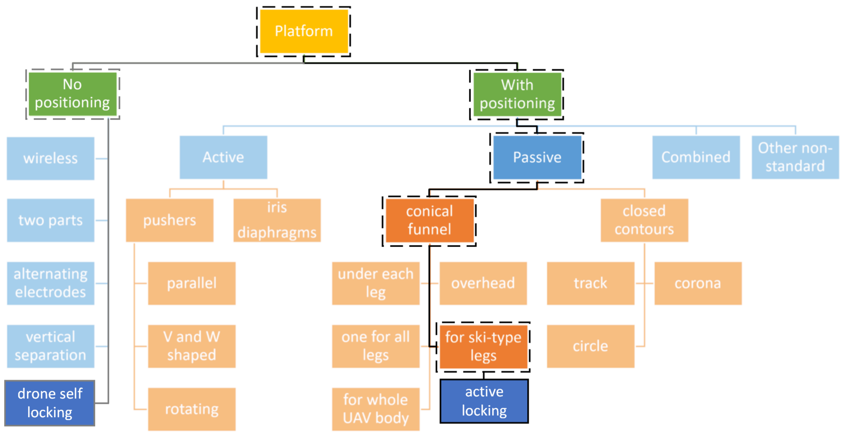
11], the authors summarized various drone landing platforms with positioning mechanisms.
However, in none of the existing works was shown a drone landing platform with active locking and unlocking capabilities that was designed specifically to use with a quadruped robot, more specifically, the Boston Dynamics Spot robot. In opposition to ground (wheeled) and aerial robot unification, the design approach had to follow specific design constraints of Spot payload as weight and dimensions, as well as take into account the locomotion of the Spot, and its degrees of freedom (extensive tilt and roll capabilities). The added value of the presented work is mainly in exploring the challenge of quadruped-aerial robot unification and demonstrating the feasibility of the concept.
Thus, the main contributions of this article stem from the design and analysis of the drone landing platforms for the Spot robot with corresponding drone designs for each of them and the final concept demonstration of the drone landing platforms in a lab environment.
Figure 2 shows our proposed solution contribution among the existing approaches [
11].
The rest of the article is structured as follows. Initially, the designs of a landing platform for Spot with corresponding drone designs are presented in
Section 2. Results and discussions of proposed designs are presented in
Section 3. Finally, the article is concluded in
Section 4.
2. Landing Platforms
In this section, concepts of drone landing platforms for the Spot robot are introduced, while taking into consideration its kinematic constraints.
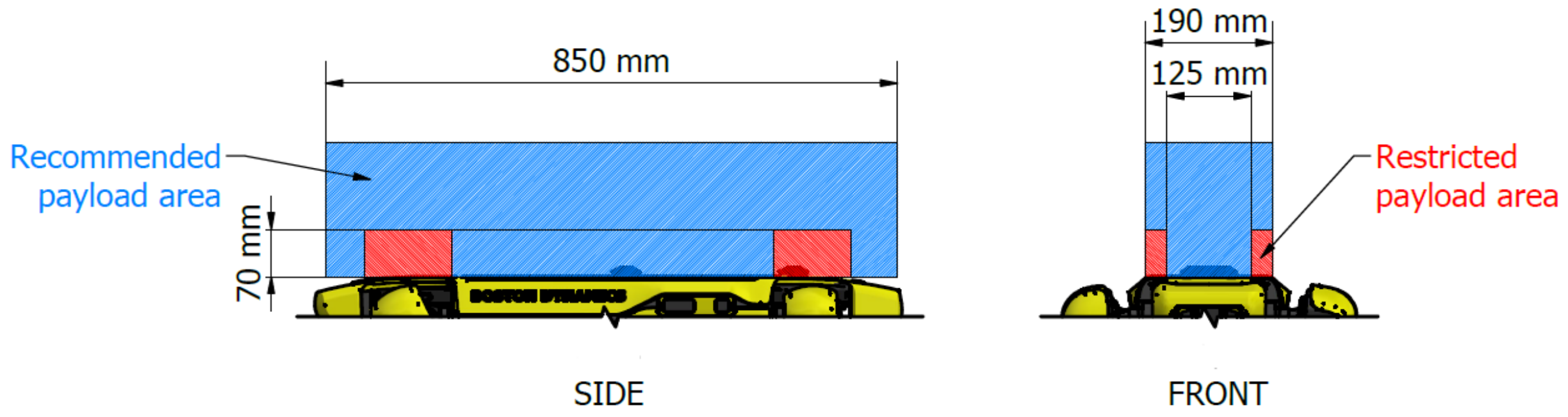
2.1. Payload for Spot Robot
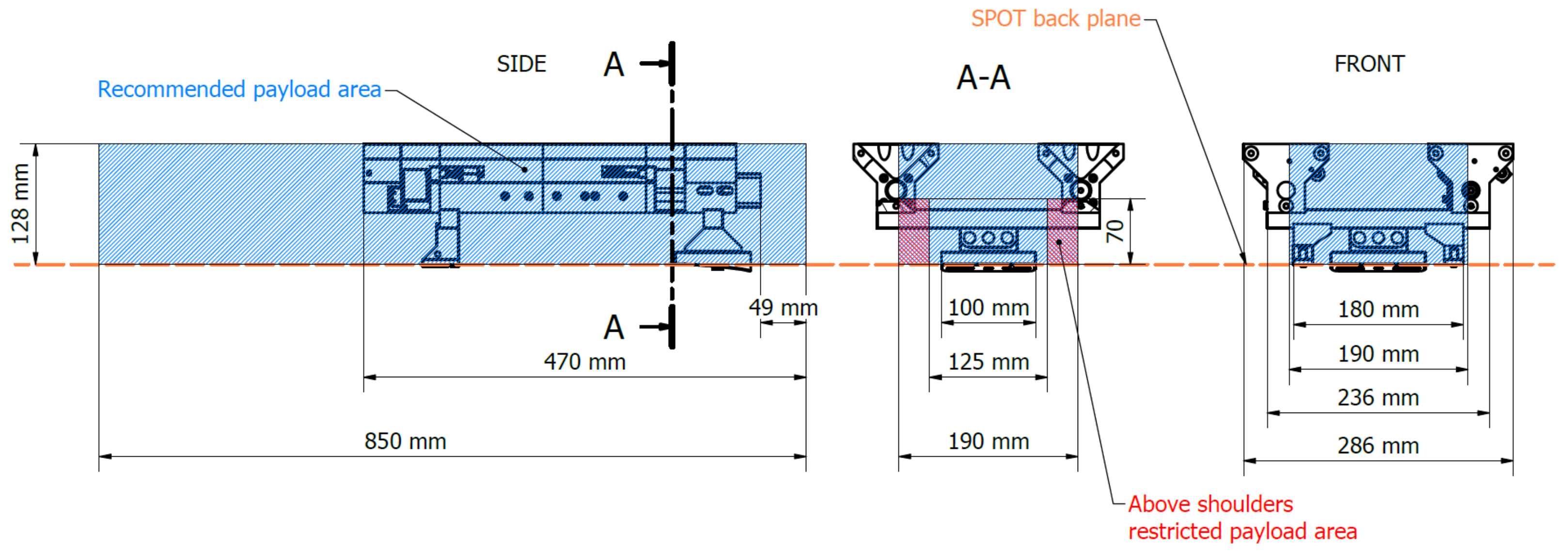
Spot is a quadruped robot capable of carrying payloads up to 14 kg. The communication between the robot and the payloads could be established via two payload connector ports that can also provide power and time synchronization. For mounting of the payload, Spot is equipped with two T-slot rails, located between the shoulders. Due to the nature of the walking robot movement, Boston Dynamics recommends to keep designed payloads in the recommended payload areas to avoid collisions with the robot legs while Spot is moving [
12]. This area is marked with blue color in
Figure 3.
Both drone landing platforms are designed considering recommendations from Boston Dynamics and the limitations and advantages of customer-grade FDM 3D printers Ultimaker UM2+/UM3 and Prusa MK3. The materials, manufacturing methods, and the overall design are adjusted for rapid in-house manufacturing and build. The structure is a combination of 3D printed parts and aluminum extrude profiles with the size of 20 mm × 20 mm.
Generally, the design of a landing platform depends on two main factors. The first one considers the drone’s size, weight, and landing gear. The second factor is the intended use of the platform. For example, a landing platform designed for launching only lightweight drones will differ significantly from a platform that should allow a heavy drone to land. In this article, we present landing platform designs for two lab-developed research drones that will be introduced in a sequel.
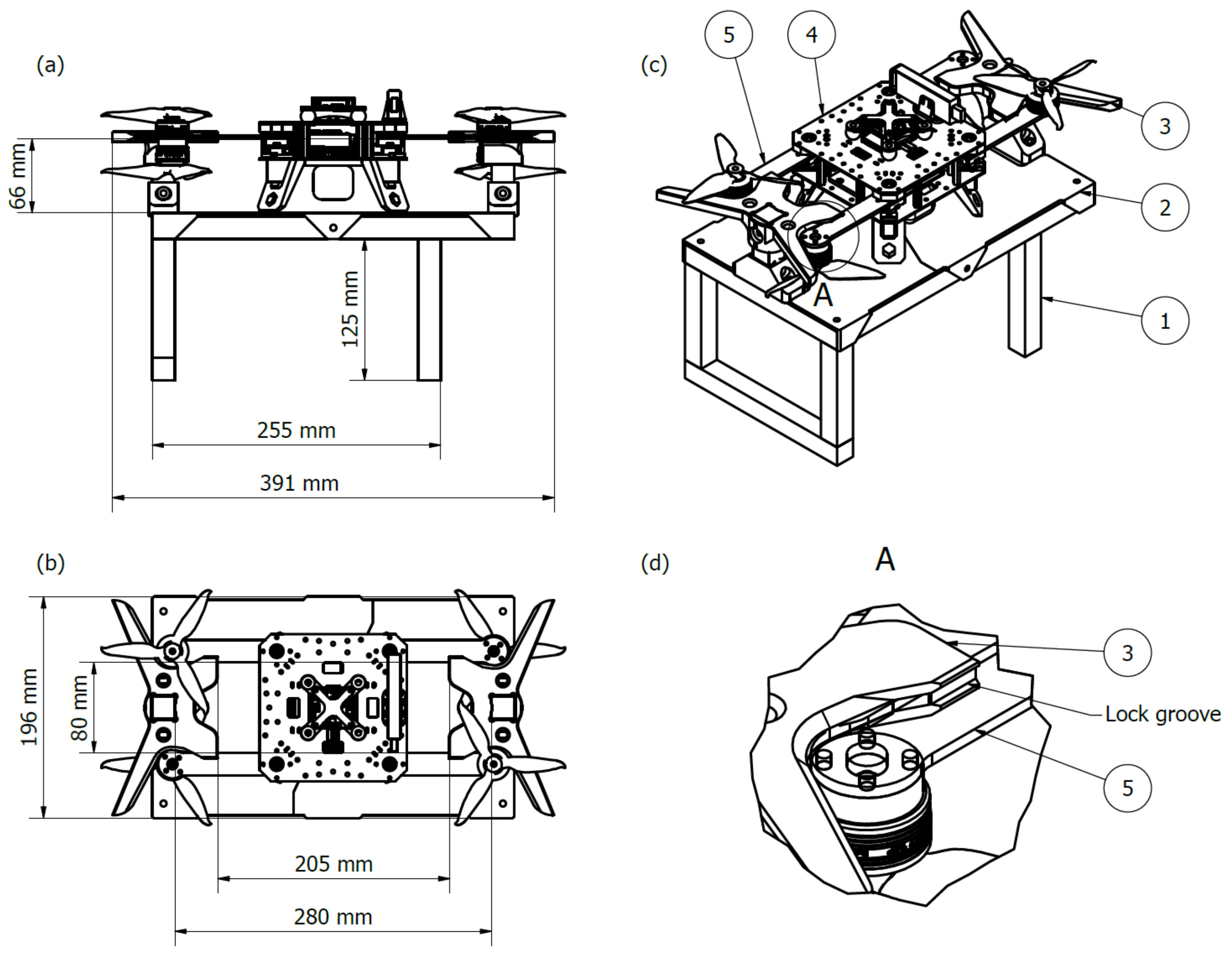
2.2. Drone Landing Platform for Re-Configurable Drone
The first landing platform was designed as an initial proof of concept of the Spot drone unification. It was developed for a reconfigurable drone referred to as “R-shafter” [
13]. The distinct feature of this drone is the actuated arms that allow it to change its frame shape configuration between “X”, “Y”, and “H”, which enables it to pass narrow openings in underground mines. The design of the landing platform takes advantage of this capability; it is completely passive and has a table-like structure, while aligning and locking are performed on the drone side.
Figure 4a–c show basic dimensions and components’ overview of the platform. The designed system works in the following way. Initially, the drone lands on the platform in X or rotated H configuration. After landing, when the rotors are not spinning, the drone will transform to the H configuration, as shown in
Figure 4. At the next step, the arms are actuated and they move until making contact with the aligner of the platform, and the drone will center itself. Finally, the arms slide into the lock grooves, as shown in detail in
Figure 4d.
This platform was designed in accordance with the Boston Dynamics payload recommendations and was mounted above the Spot onboard computer that is placed on its back and uses the payload T-slot rails for mounting, as depicted in
Figure 5.
2.3. Drone Landing Platform for Fixed Frame Drone
This landing platform was designed for the Spot robot unification with a larger drone that is referred to as Shafter [
14]. Its dimensions, excluding the 12-inch propellers, are
, 513 mm × 335 mm × 339 mm, and the total weight is 3615 g. The landing platform design fulfills the following requirements such that the platform is able to allow take-off and landing of the drone. At the same time, the drone can be securely locked in the platform when the Spot robot is moving. The locking and unlocking sequence is controlled via the Robot Operating System (ROS) framework that is installed on the Spot onboard computer.
Recommended payload areas for Spot (
Figure 3) were first examined in the intended usage environment with mostly flat floors, avoiding climbing intricate obstacles and staircases. This allowed us to relax the demotions of the recommended areas a bit, as shown in
Figure 6, so the landing platform is slightly interfering with the restricted zone above the rear shoulders and is expanding outside of the maximum recommended width boundaries. In extended testing procedures in the lab environment, collisions between the robot legs and the platform were not detected.
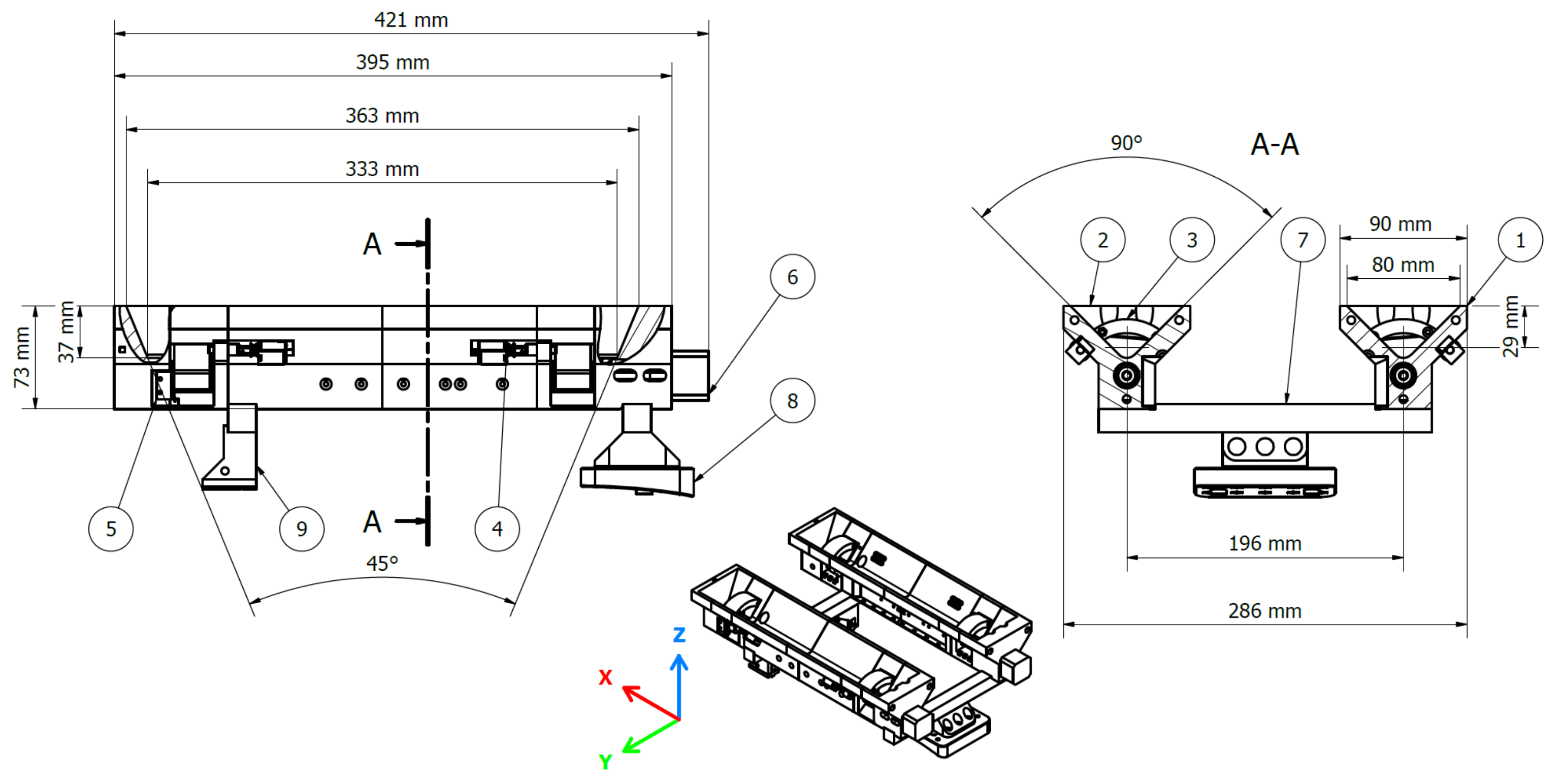
The landing platform is designed with a passive drone landing alignment and an active landing gear locking. Its core component is the two rails, which have openings of 90 degrees in the X axis and 45 degrees in the Y axis. This design can compensate for a total error at landing of 80 mm along the Y axis and 31 mm along the X axis, respectively, which was experimentally verified in the lab environment.
The platform is attached to the Spot robot using the payload T-slot rails in the front and custom-made rear mount plate in the back, as shown in
Figure 7. The rear mount plate repurposes the rear body panel screws. This setup ensures a secure connection and at the same time provides enough clearance above the rear shoulders when the robot is moving, especially during the transition to and from the seating position.
The active locking is represented by a pair of rotating clamps in each rail, which are controlled by the NEMA14 stepper motor. Each clamp is secured in the locked state by a door-lock-style solenoid, and by default, clamps are closed and secured with the solenoids. This state does not require any power, and it provides a fail-safe in case of power shortage when the drone is loaded. When the drone is ready to take off, the unlocking sequence is performed by retracting solenoids so clamps can move freely and rotate to the open position and thus the drone can take off. This process is controlled using an onboard Arduino computer tied to the landing platform. The schematics of the landing platform are depicted in
Figure 7.
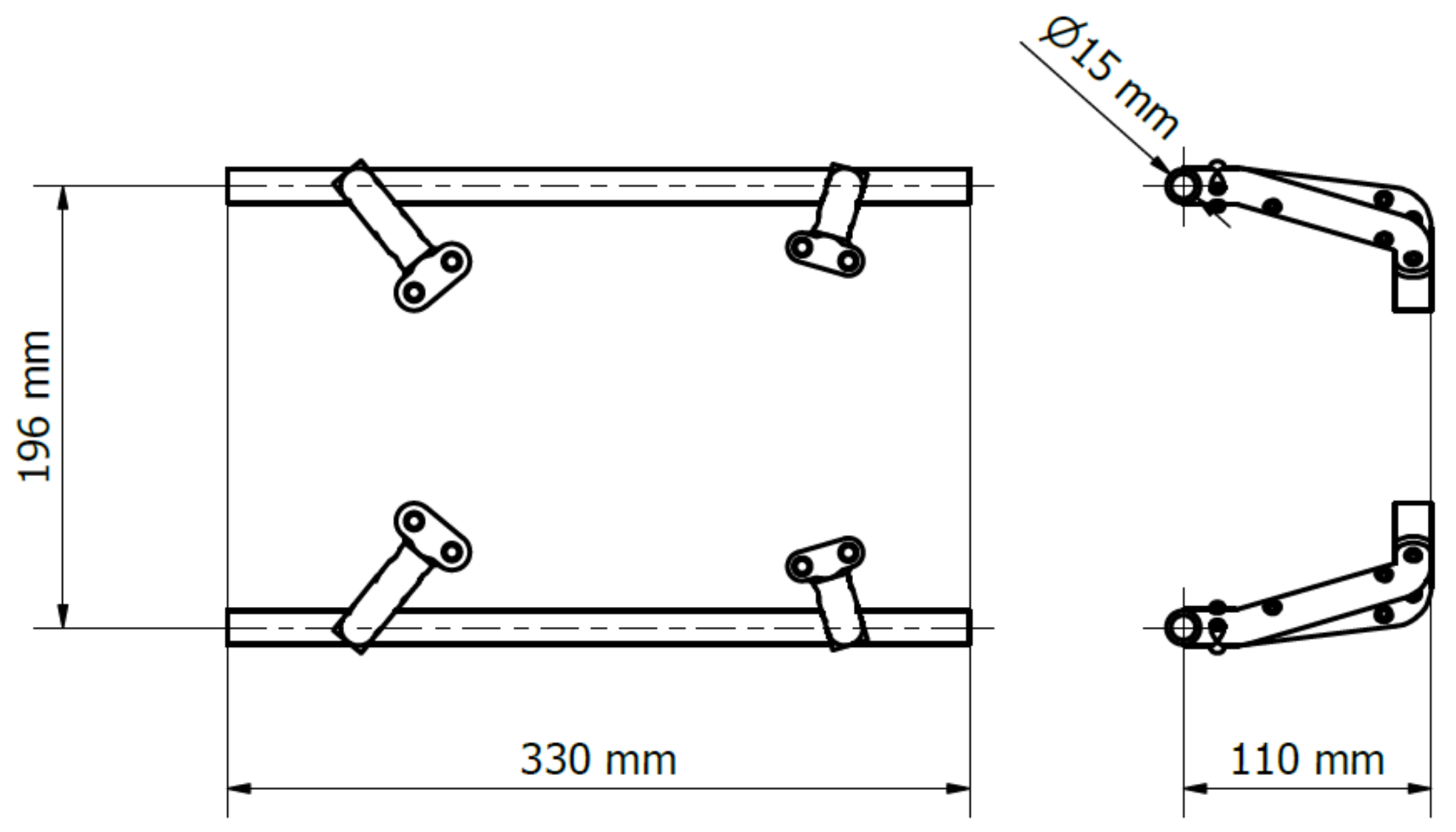
The landing gear on the Shafter drone, shown in
Figure 8, was designed while considering the design and dimensions of the landing platform. It has a ski-style landing gear with two carbon fiber tubes with diameter 15 mm and length of 330 mm in its base. The legs are 3D-printed from Nylon filament (Taulman3D PCTPE).
This landing platform design can be used with different drones, by simply redesigning their landing gear, which generalizes this design for drones with similar size and weight.
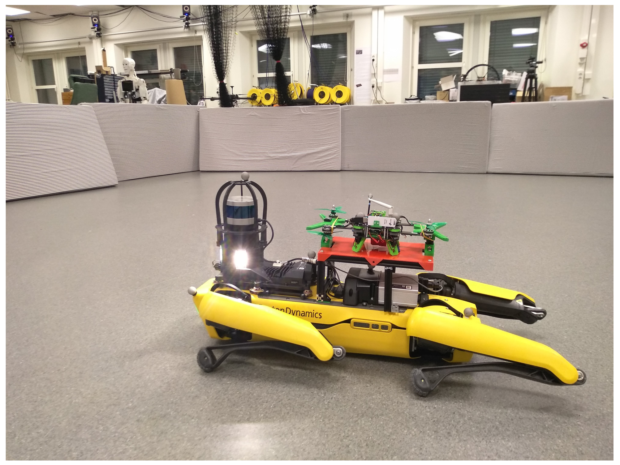
The demonstration of the Spot-Shafter unification is shown in
Figure 9.
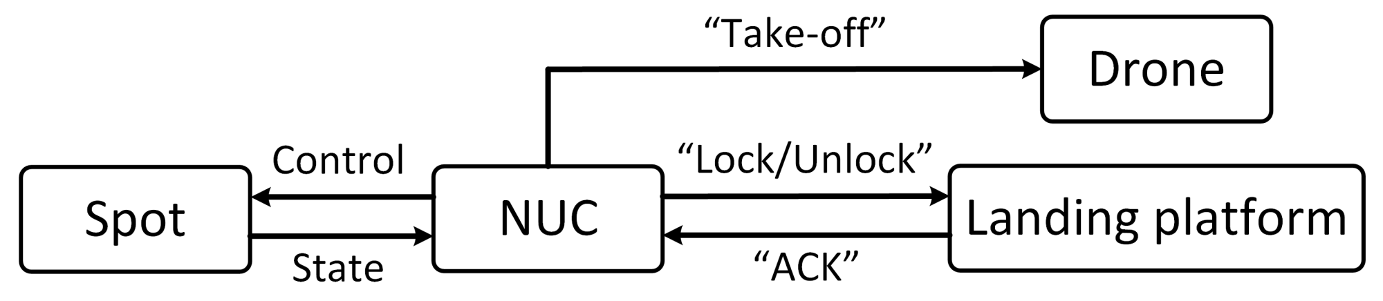
The overall unified legged-aerial system is controlled by an onboard Intel NUC computer mounted on Spot, which operates under the Ubuntu 18.04 LTS operating system with ROS Melodic framework. To establish a communication between the landing platform and NUC, it utilizes ROS services (
http://wiki.ros.org/Services, accessed on 20 February 2022). Using them, the “lock/unlock” request is sent from the onboard computer to actuate the landing platform. When the actuation process is complete, the platform sends a feedback message “ACK” that confirms that the actuation completed successfully to NUC. On receiving this message, a “take-off” command is sent from NUC to drone. The overall communication architecture is shown in
Figure 10.
3. Experimental Evaluation
In this section, results will be presented on the experimental evaluation of the proposed designs of the landing platforms.
Both landing platforms were experimentally evaluated in the lab environment, while the platform for Shafter was also evaluated in the field tests, as is shown in the video (
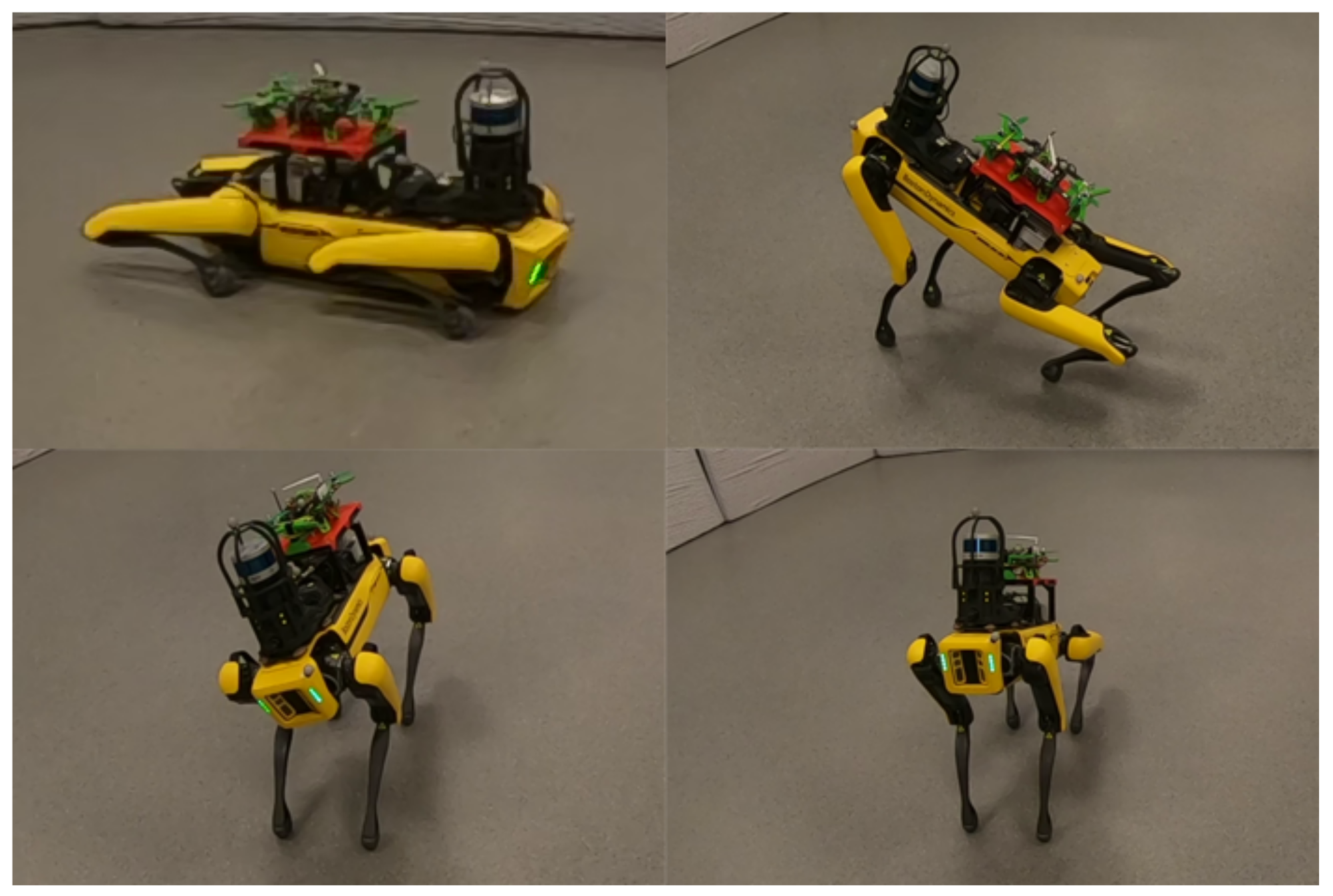
https://youtu.be/UDn_q-Ju9F8, accessed on 20 February 2022). In the case of the landing platform for the reconfigurable drone, the first part of the evaluation process aimed to identify the presence of collisions between Spot legs and the landing platform. In this test, to manually control Spot, extreme body positions and rotations were commanded, as shown in
Figure 11; however, during these tests, collisions were not detected.
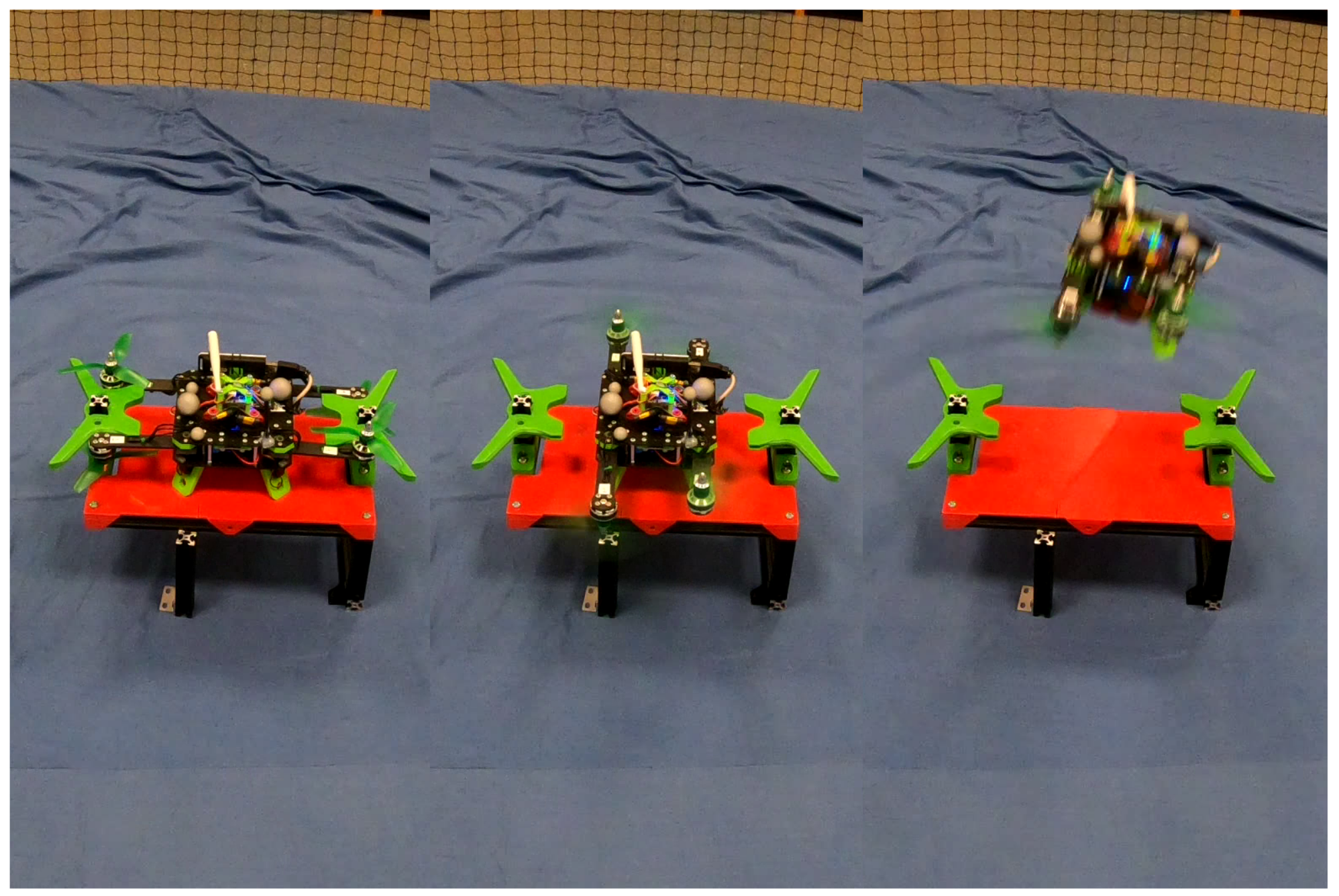
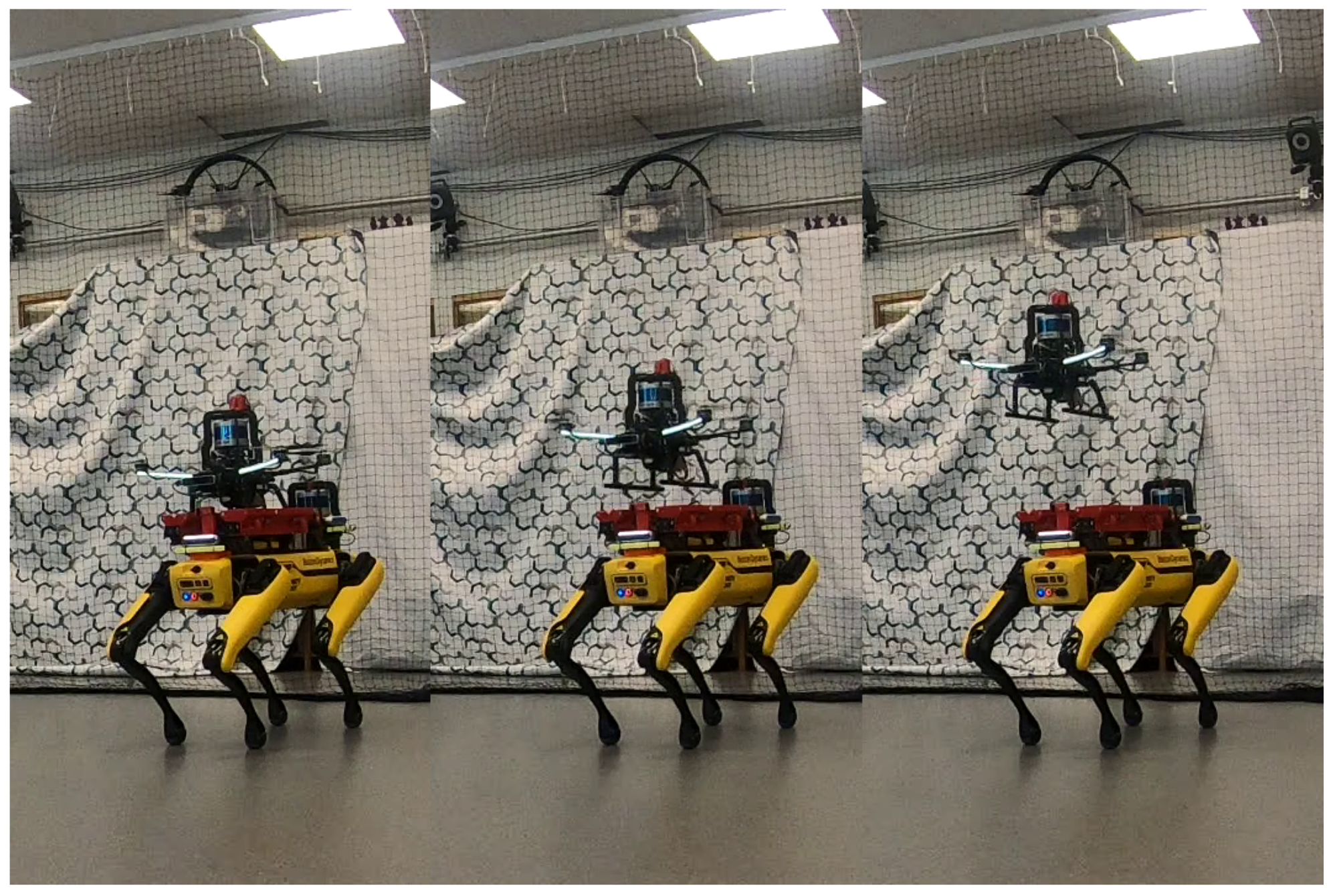
The next set of tests concerned the evaluation of the drone take-off capabilities in which the drone was locking and unlocking itself from the platform and performing take off (
Figure 12). In these tests, the R-Shafter was manually controlled. The evaluation tests demonstrated viability of the proposed design.
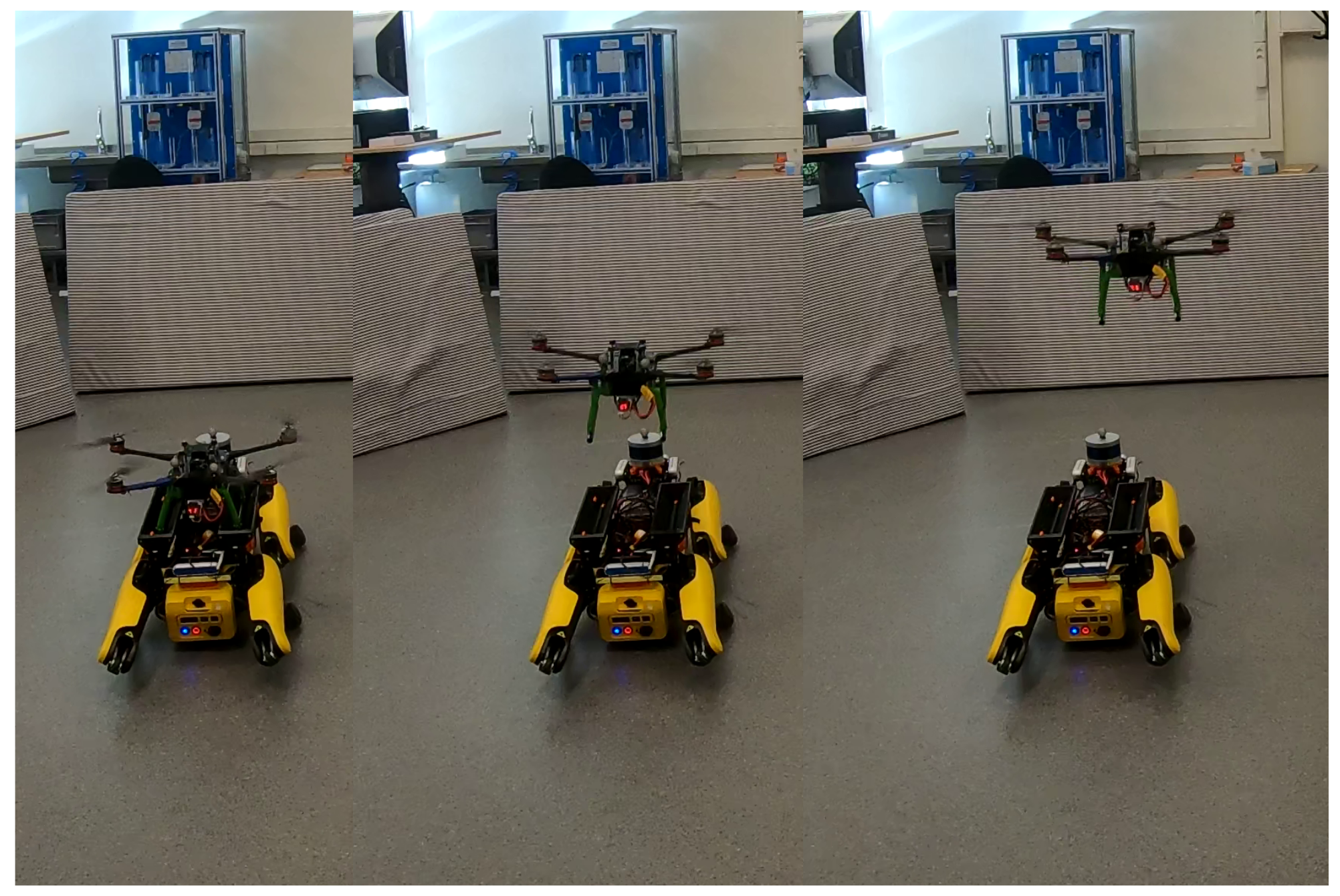
The main focus of the experimental evaluation was given to the landing platform for the Shafter drone. The evaluation process included the evaluation of the robustness of the locking mechanism to securely keep drone manual (
Figure 13) and autonomous (
Figure 14) take-off tests from the landing platform in the lab environment. In the autonomous take-off tests, for position estimation and waypoint navigation, a Vicon motion capture system was utilized. All the evaluation tests were accomplished successfully.
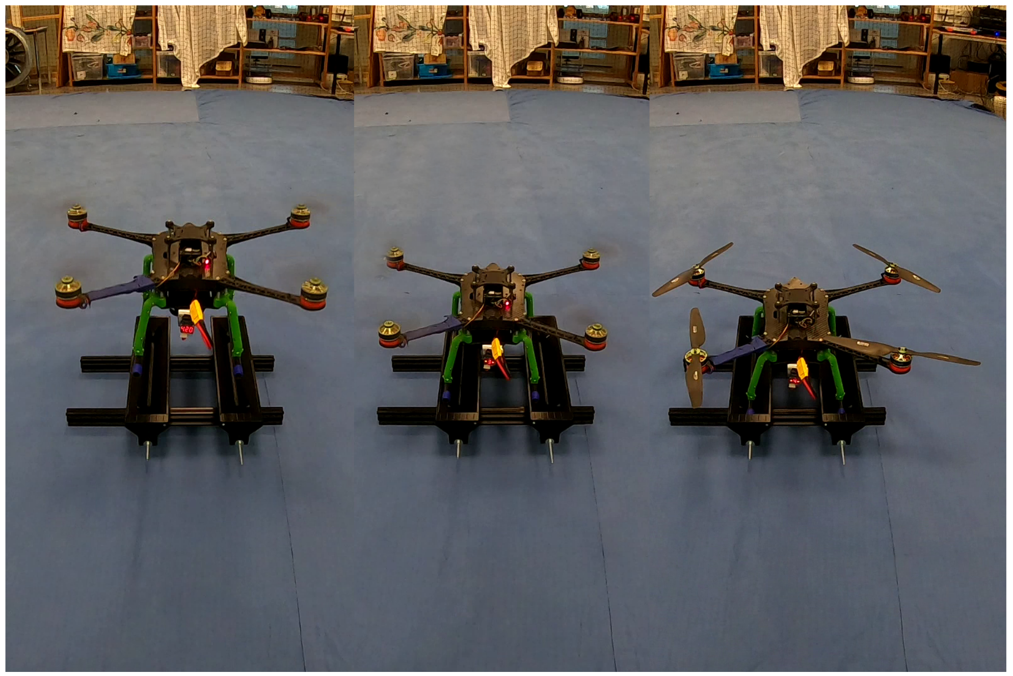
The self-alignment capability of the landing platform was tested while performing manual landing maneuvers on the standalone platform (
Figure 15). The tests carried out demonstrated the viability of self-aligning functionality of the landing platform.
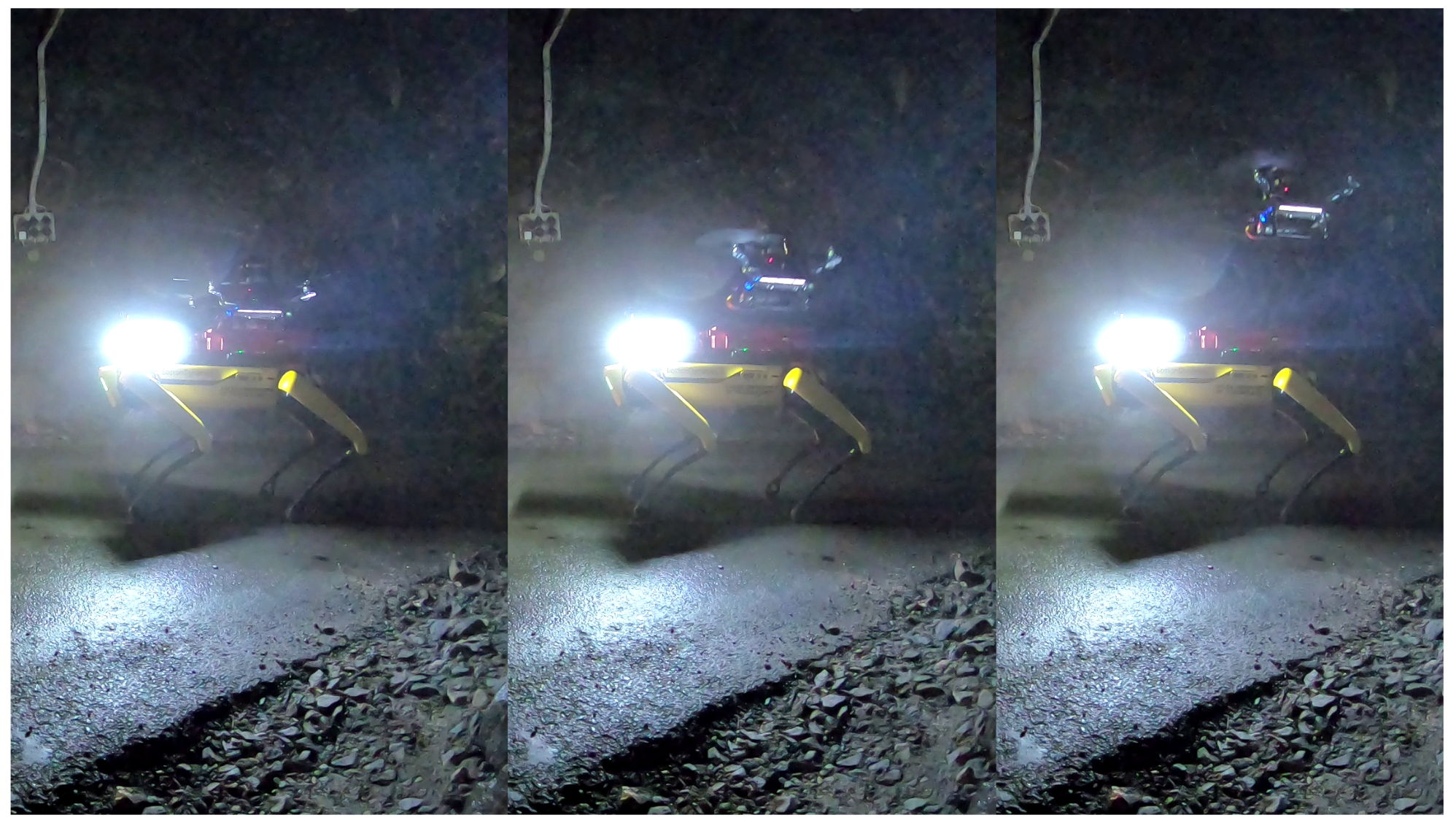
Overall, the completed set of tests with Spot and Shafter proved the feasibility of the unification concept in the lab. The conducted experiments also proved that the platform is robust enough for testing in the field. Furthermore, the platform for Shafter was evaluated as a part of large-scale experiments in the underground tunnel (
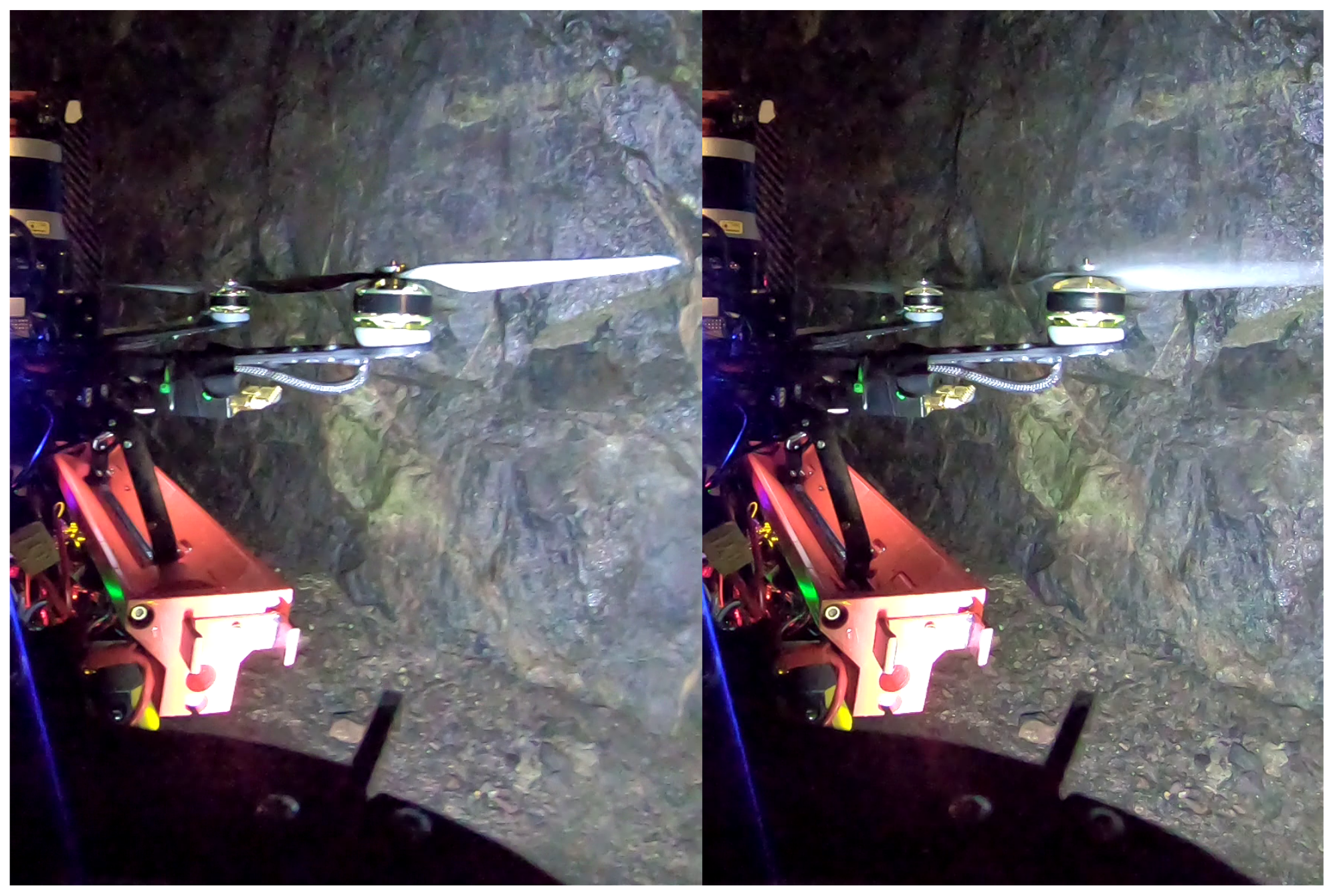
Figure 16). At the beginning of this experiment, the drone was attached and locked on the platform. In the sequel, the Spot robot autonomously navigated from the starting point to the point of drone release. At this point, the platform was unlocked and the drone performed autonomous take-off, as depicted in
Figure 17. All the field tests successfully demonstrated the robustness of the Spot–Shafter unification and proved the robustness of the designed landing platform.
4. Conclusions
In this study, we introduced the concept of unification of Spot with aerial robots. For each drone, we proposed the individual landing platform design that is based on its weight, dimensions, and frame. The landing platform for R-Shafter was successfully evaluated in the lab environment in drone holding and take-off tests, which demonstrated the proof of concept. The platform designed for the Shafter drone had more extensive evaluations including both lab and field experiments in the underground environment, which proved the viability of the designed concept. As a part of future activities, R-Shafter will be evaluated in autonomous take-off experiments in the lab and in the tunnel environment. Moreover, both platforms will be evaluated and tested in full field experiments with autonomous take off and landing in unification missions.


