
Uni-Planar MIMO Antenna for Sub-6 GHz 5G Mobile Phone Applications

 ,
,  ,
, 
 ,
,  ,
,  and
and
Abstract
:1. Introduction
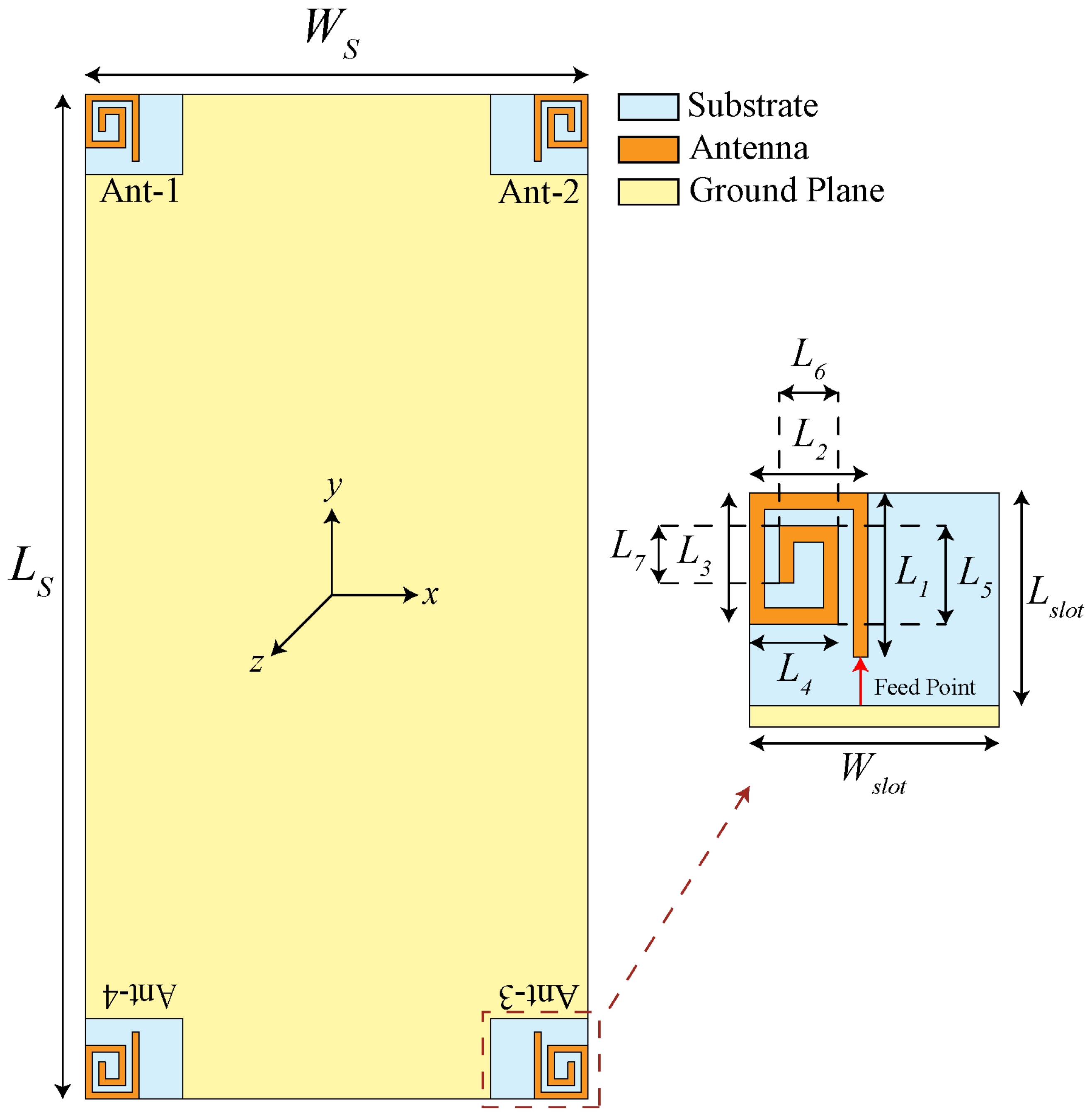
2. Proposed Uni-Planar MIMO Antenna
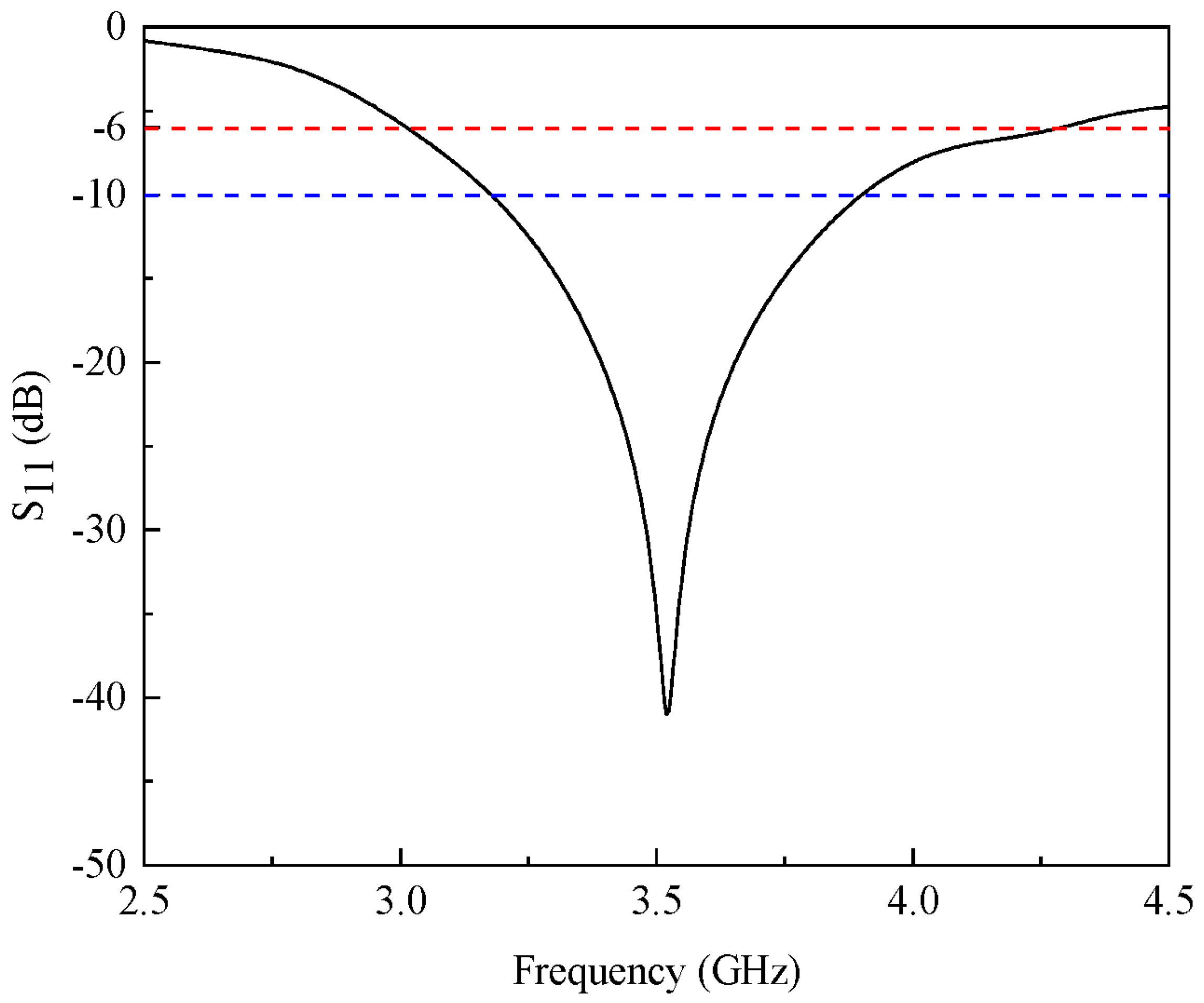
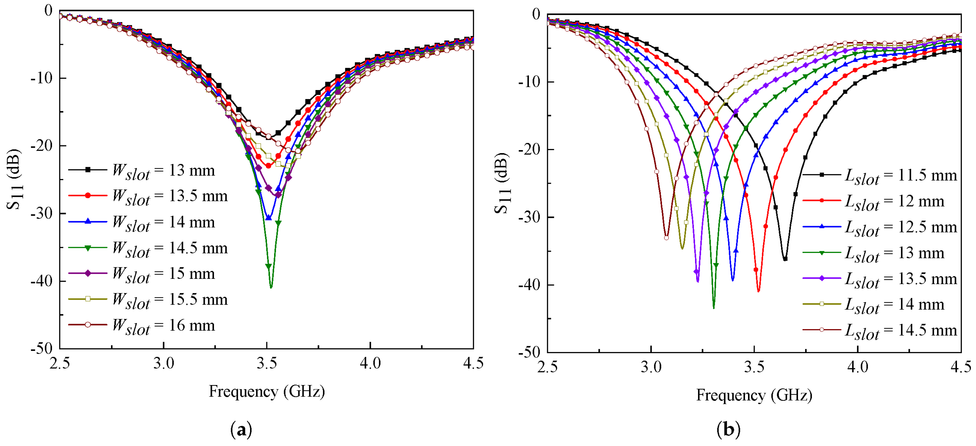
2.1. Characteristics of Single-Antenna Elements
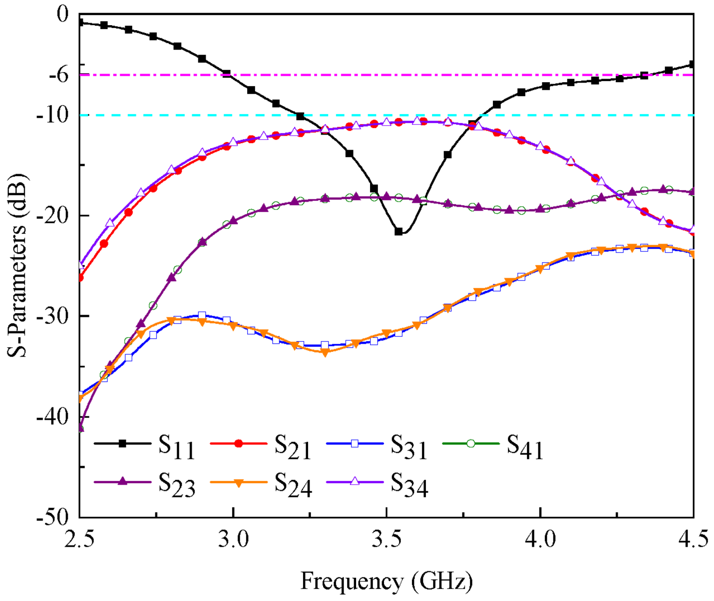
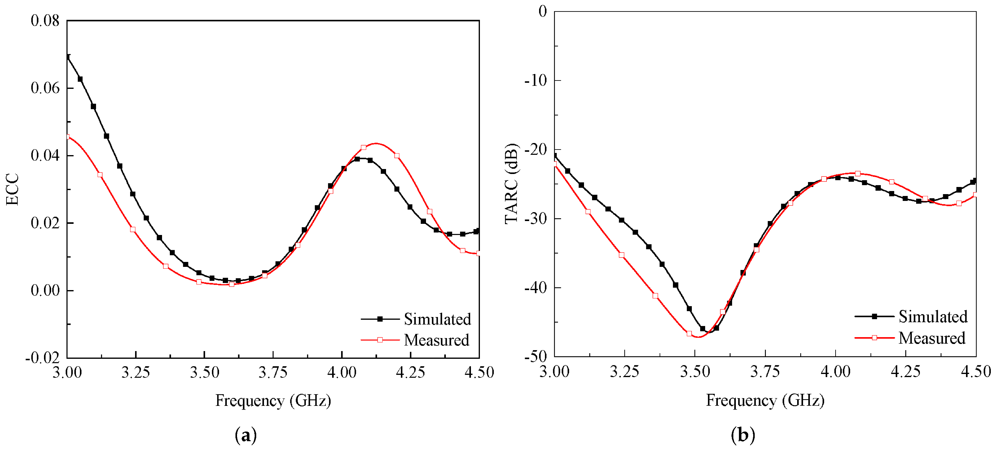
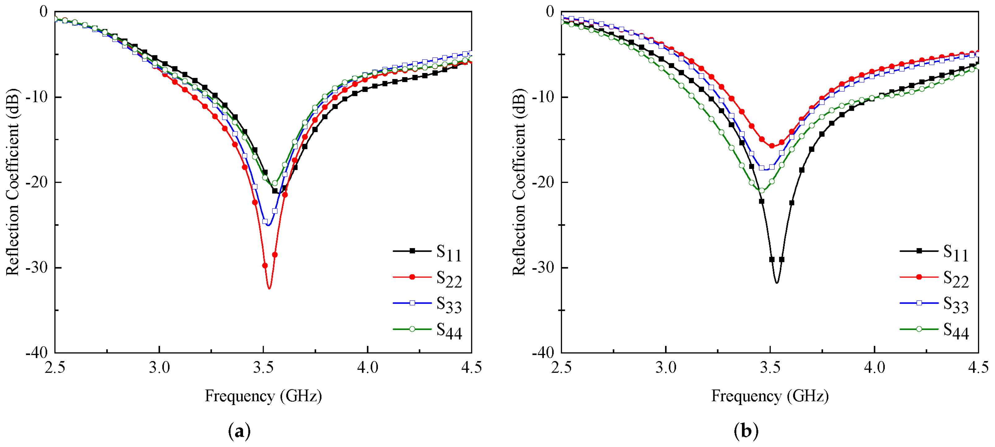
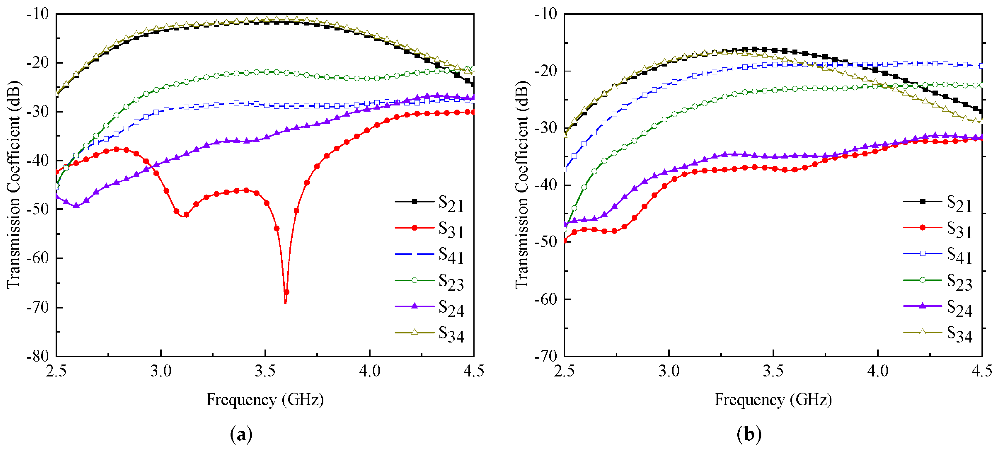
2.2. Characteristics of Proposed MIMO Antenna
2.3. Fabrication and Measurements
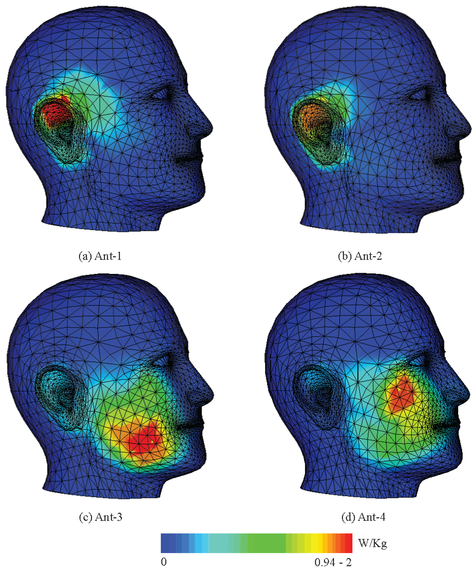
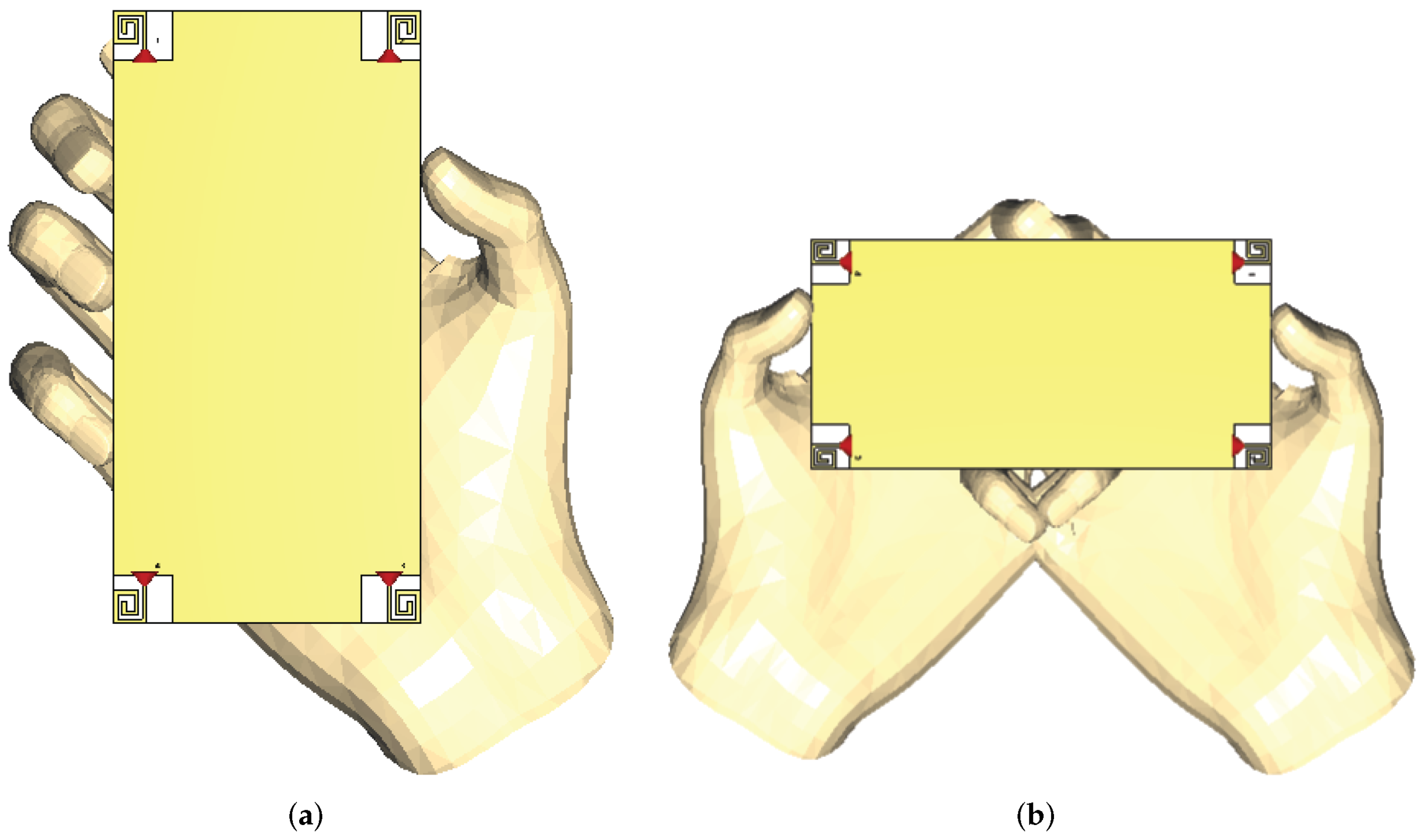
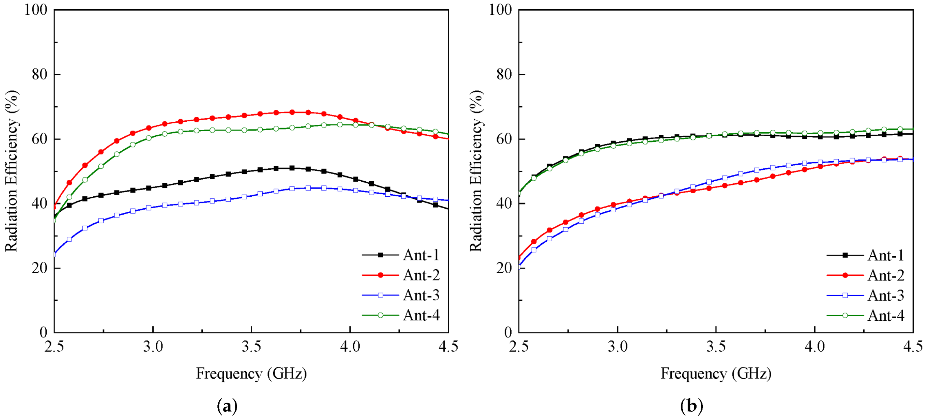
2.4. User’s Impact on Antenna Characteristics
3. Conclusions
Author Contributions
Funding
Institutional Review Board Statement
Informed Consent Statement
Data Availability Statement
Acknowledgments
Conflicts of Interest
References
- Osseiran, A.; Boccardi, F.; Braun, V.; Kusume, K.; Marsch, P.; Maternia, M.; Queseth, O.; Schellmann, M.; Schotten, H.; Taoka, H.; et al. Scenarios for 5G mobile and wireless communications: The vision of the METIS project. IEEE Commun. Mag. 2014, 52, 26–35. [Google Scholar] [CrossRef]
- Kammoun, A.; Debbah, M.; Alouini, M.S. Design of 5G full dimension massive MIMO systems. IEEE Trans. Commun. 2017, 66, 726–740. [Google Scholar]
- Yang, H.H.; Quek, T.Q. Massive MIMO Meets Small Cell; Springer: Berlin/Heidelberg, Germany, 2017. [Google Scholar]
- Ojaroudi Parchin, N.; Jahanbakhsh Basherlou, H.; Al-Yasir, Y.I.; Abd-Alhameed, R.A.; Abdulkhaleq, A.M.; Noras, J.M. Recent developments of reconfigurable antennas for current and future wireless communication systems. Electronics 2019, 8, 128. [Google Scholar] [CrossRef] [Green Version]
- Andrews, J.G.; Buzzi, S.; Choi, W.; Hanly, S.V.; Lozano, A.; Soong, A.C.; Zhang, J.C. What will 5G be? IEEE J. Sel. Areas Commun. 2014, 32, 1065–1082. [Google Scholar] [CrossRef]
- Parchin, N.O.; Al-Yasir, Y.I.A.; Abd-Alhameed, R.A. Microwave/RF Components for 5G Front-End Systems; Avid Science: Hyderabad, India, 2019. [Google Scholar]
- Li, Y.; Luo, Y.; Yang, G. High-isolation 3.5 GHz eight-antenna MIMO array using balanced open-slot antenna element for 5G smartphones. IEEE Trans. Antennas Propag. 2019, 67, 3820–3830. [Google Scholar] [CrossRef]
- Ullah, R.; Ullah, S.; Ullah, R.; Faisal, F.; Mabrouk, I.B.; Al Hasan, M.J. A 10-Ports MIMO Antenna System for 5G Smart-Phone Applications. IEEE Access 2020, 8, 218477–218488. [Google Scholar] [CrossRef]
- Zhang, X.; Li, Y.; Wang, W.; Shen, W. Ultra-wideband 8-port MIMO antenna array for 5G metal-frame smartphones. IEEE Access 2019, 7, 72273–72282. [Google Scholar] [CrossRef]
- Abdullah, M.; Kiani, S.H.; Iqbal, A. Eight element multiple-input multiple-output (MIMO) antenna for 5G mobile applications. IEEE Access 2019, 7, 134488–134495. [Google Scholar] [CrossRef]
- Jiang, W.; Liu, B.; Cui, Y.; Hu, W. High-isolation eight-element MIMO array for 5G smartphone applications. IEEE Access 2019, 7, 34104–34112. [Google Scholar] [CrossRef]
- Ojaroudi Parchin, N.; Jahanbakhsh Basherlou, H.; Alibakhshikenari, M.; Ojaroudi Parchin, Y.; Al-Yasir, Y.I.; Abd-Alhameed, R.A.; Limiti, E. Mobile-phone antenna array with diamond-ring slot elements for 5G massive MIMO systems. Electronics 2019, 8, 521. [Google Scholar] [CrossRef] [Green Version]
- Parchin, N.O.; Al-Yasir, Y.I.; Basherlou, H.J.; Abd-Alhameed, R.A.; Noras, J.M. Orthogonally dual-polarised MIMO antenna array with pattern diversity for use in 5G smartphones. IET Microw. Antennas Propag. 2020, 14, 457–467. [Google Scholar] [CrossRef]
- Kiani, S.H.; Altaf, A.; Abdullah, M.; Muhammad, F.; Shoaib, N.; Anjum, M.R.; Damaševičius, R.; Blažauskas, T. Eight element side edged framed MIMO antenna array for future 5G smart phones. Micromachines 2020, 11, 956. [Google Scholar] [CrossRef] [PubMed]
- Iffat Naqvi, S.; Hussain, N.; Iqbal, A.; Rahman, M.; Forsat, M.; Mirjavadi, S.S.; Amin, Y. Integrated LTE and Millimeter-Wave 5G MIMO Antenna System for 4G/5G Wireless Terminals. Sensors 2020, 20, 3926. [Google Scholar] [CrossRef] [PubMed]
- Parchin, N.O.; Basherlou, H.J.; Al-Yasir, Y.I.; Abd-Alhameed, R.A. A broadband multiple-input multiple-output loop antenna array for 5G cellular communications. AEU-Int. J. Electron. Commun. 2020, 127, 153476. [Google Scholar] [CrossRef]
- Parchin, N.O.; Al-Yasir, Y.I.; Abdulkhaleq, A.M.; Basherlou, H.J.; Ullah, A.; Abd-Alhameed, R.A. A New broadband MIMO antenna system for sub 6 GHz 5G cellular Communications. In Proceedings of the 2020 14th European Conference on Antennas and Propagation (EuCAP), Copenhagen, Denmark, 15–20 March 2020; pp. 1–4. [Google Scholar]
- Ojaroudi Parchin, N.; Jahanbakhsh Basherlou, H.; Al-Yasir, Y.I.; Abdulkhaleq, A.M.; Patwary, M.; Abd-Alhameed, R.A. A new CPW-Fed diversity antenna for MIMO 5G smartphones. Electronics 2020, 9, 261. [Google Scholar] [CrossRef] [Green Version]
- Ahmad, U.; Ullah, S.; Rafique, U.; Choi, D.Y.; Ullah, R.; Kamal, B.; Ahmad, A. MIMO Antenna System With Pattern Diversity for Sub-6 GHz Mobile Phone Applications. IEEE Access 2021, 9, 149240–149249. [Google Scholar] [CrossRef]
- AI-Yasir, Y.I.; Parchin, N.O.; Alabdullah, A.; Mshwat, W.; Ullah, A.; Abd-Alhameed, R. New pattern reconfigurable circular disk antenna using two PIN diodes for WiMax/WiFi (IEEE 802.11a) applications. In Proceedings of the 2019 16th International Conference on Synthesis, Modeling, Analysis and Simulation Methods and Applications to Circuit Design (SMACD), Lausanne, Switzerland, 15–18 July 2019; pp. 53–56. [Google Scholar]
- Mazloum, J.; Ghorashi, S.A.; Ojaroudi, M.; Ojaroudi, N. Compact Triple-Band S-Shaped Monopole Diversity Antenna for MIMO Applications. Appl. Comput. Electromagn. Soc. J. 2015, 30, 975–980. [Google Scholar]
- Kumar, A.; Ansari, A.Q.; Kanaujia, B.K.; Kishor, J. High isolation compact four-port MIMO antenna loaded with CSRR for multiband applications. Frequenz 2018, 72, 415–427. [Google Scholar] [CrossRef]
- Sharawi, M.S. Printed multi-band MIMO antenna systems and their performance metrics [wireless corner]. IEEE Antennas Propag. Mag. 2013, 55, 218–232. [Google Scholar] [CrossRef]
- Stuchly, M. Electromagnetic fields and health. IEEE Potentials 1993, 12, 34–39. [Google Scholar] [CrossRef]
- Ojaroudiparchin, N.; Shen, M.; Zhang, S.; Pedersen, G.F. A switchable 3-D-coverage-phased array antenna package for 5G mobile terminals. IEEE Antennas Wirel. Propag. Lett. 2016, 15, 1747–1750. [Google Scholar] [CrossRef] [Green Version]
- Moustafa, J.; McEwan, N.; Abd-Alhameed, R.; Excell, P. Low SAR phased antenna array for mobile handsets. Appl. Comput. Electromagn. Soc. J. 2006, 21, 196. [Google Scholar]


| 150 | 75 | 10 | 8 | 8 | 6 |
| − | |||||
| 6 | 4 | 3.5 | 12 | 14.5 | − |
| Ref. | Dimensions | Antenna | Electrical | Frequency Band | Peak Gain | Efficiency | Isolation | ECC |
|---|---|---|---|---|---|---|---|---|
| (mm) | Elements | Dimensions | (GHz) | (dBi) | (%) | (dB) | ||
| [7] | 150 × 80 | 8 | 0.239 × 0.128 | 3.4–3.6 | − | >62 | >17 | <0.05 |
| [8] | 150 × 80 | 8 | 0.128 × 0.192 | 3.4–3.6 | 2–4 | 60–70 | >10 | <0.1 |
| [10] | 150 × 75 | 8 | 0.15 × 0.06 | 2.5–3.6 | 2.3 | 65 | >13 | <0.2 |
| [11] | 124 × 74 | 8 | 0.056 × 0.14 | 3.3–3.6 | 4.3–4.8 | 40 | >15 | <0.15 |
| [12] | 150 × 75 | 8 | 0.288 × 0.288 | 3.2–4 | 3 | 80 | 20 | <0.01 |
| [13] | 150 × 75 | 8 | 0.291 × 0.291 | 3.3–3.9 | 3 | 60–80 | 18 | <0.01 |
| [14] | 150 × 75 | 8 | 0.186 × 0.093 | 3.4–3.6 | 3.5–3.9 | 50–60 | >13 | <0.1 |
| [16] | 150 × 75 | 8 | 0.157 × 0.058 | 3.2–4 | 3.3–4 | 70–80 | ≥10 | <0.005 |
| [18] | 150 × 75 | 8 | 0.24 × 0.038 | 3.4–4.4 | 3.6 | >90 | >16 | <0.005 |
| This Work | 150 × 75 | 4 | 0.169 × 0.14 | 3.21–3.81 | 3.64 | >90 | >10 | <0.02 |
Publisher’s Note: MDPI stays neutral with regard to jurisdictional claims in published maps and institutional affiliations. |
© 2022 by the authors. Licensee MDPI, Basel, Switzerland. This article is an open access article distributed under the terms and conditions of the Creative Commons Attribution (CC BY) license (https://creativecommons.org/licenses/by/4.0/).
Share and Cite
Rafique, U.; Khan, S.; Ahmed, M.M.; Kiani, S.H.; Abbas, S.M.; Saeed, S.I.; Alibakhshikenari, M.; Dalarsson, M. Uni-Planar MIMO Antenna for Sub-6 GHz 5G Mobile Phone Applications. Appl. Sci. 2022, 12, 3746. https://doi.org/10.3390/app12083746
Rafique U, Khan S, Ahmed MM, Kiani SH, Abbas SM, Saeed SI, Alibakhshikenari M, Dalarsson M. Uni-Planar MIMO Antenna for Sub-6 GHz 5G Mobile Phone Applications. Applied Sciences. 2022; 12(8):3746. https://doi.org/10.3390/app12083746
Chicago/Turabian StyleRafique, Umair, Suleman Khan, Muhammad Mansoor Ahmed, Saad Hassan Kiani, Syed Muzahir Abbas, Sohail Imran Saeed, Mohammad Alibakhshikenari, and Mariana Dalarsson. 2022. "Uni-Planar MIMO Antenna for Sub-6 GHz 5G Mobile Phone Applications" Applied Sciences 12, no. 8: 3746. https://doi.org/10.3390/app12083746
APA StyleRafique, U., Khan, S., Ahmed, M. M., Kiani, S. H., Abbas, S. M., Saeed, S. I., Alibakhshikenari, M., & Dalarsson, M. (2022). Uni-Planar MIMO Antenna for Sub-6 GHz 5G Mobile Phone Applications. Applied Sciences, 12(8), 3746. https://doi.org/10.3390/app12083746