Review

Recent Development of High-Energy Short-Pulse Lasers with Cryogenically Cooled Yb:YAG

1
Aerospace Information Research Institute, Chinese Academy of Sciences, Beijing 100094, China
2
College of Optoelectronics, University of Chinese Academy of Sciences, Beijing 100039, China
*
Authors to whom correspondence should be addressed.
Appl. Sci. 2022, 12(8), 3711; https://doi.org/10.3390/app12083711
Submission received: 27 February 2022 / Revised: 30 March 2022 / Accepted: 1 April 2022 / Published: 7 April 2022
(This article belongs to the Special Issue Laser Technologies and Nonlinear Optics in Surface Sciences)

Abstract

:
High-power solid-state lasers are among the hot research directions at the forefront of laser research and have major applications in industrial processing, laser-confined nuclear fusion, and high-energy particle sources. In this paper, the properties of Yb:YAG and Nd:YAG crystals as gain media for high-power solid-state lasers were briefly compared, according to the results of which Yb:YAG crystals are more suitable for high-power applications. Then, the effects of the thermodynamic and spectral properties of Yb:YAG crystals with temperature were analyzed in detail, and it was shown that the laser beams amplified by the cryogenically cooled Yb:YAG crystals could have higher beam quality, higher pump absorption efficiency, lower pump threshold, and higher gain. The change in properties of Yb:YAG crystal at low temperature makes it more suitable as a gain medium for high-power lasers. Subsequently, two types of kilowatt-class lasers using cryogenically cooled Yb:YAG crystals as gain media are introduced—100 J, 10 Hz nanosecond lasers and 1 J, 1 kHz picosecond lasers. Their configuration, main parameters, and typical output results were analyzed. Finally, future directions in the development of cryogenically cooled Yb:YAG lasers are discussed.

1. Introduction

In 1965, Johnson obtained the first laser using Yb:YAG crystals as the gain medium using flashlamp pumping [1]. However, due to the poor match between the absorption spectrum of Yb:YAG crystal and the pump light spectrum, resulting in low laser efficiency, it has not received much attention, while Nd:YAG crystal has been fully developed due to its good physical and chemical properties. The energy, power, repetition frequency, and other indicators of solid-state lasers are rapidly improving, and they play irreplaceable roles in industrial processing, military, laser-confined nuclear fusion, and other fields [2]. With the advent of InGaAs laser diodes, Yb:YAG crystals have returned to the field of vision of researchers due to their excellent optical properties [3]. First, the absorption wavelength of Yb:YAG crystal is closer to the emission wavelength and has a lower quantum loss. In addition, it has no upper energy level conversion, which greatly reduces the thermal load, and the thermal effect is about 3 times smaller than that of Nd:YAG crystal [4]; secondly, the energy level lifetime of Yb:YAG crystal is about 4 times that of Nd:YAG crystal, which is conducive to storing more energy [5]; thirdly, compared with Nd3+, Yb3+ and YAG lattice match better, which can achieve higher doping concentration. The crystal quality is good, and the defects are few [2]; finally, the absorption bandwidth of Yb:YAG crystal at 940 nm is about 18 nm, which is much larger than the absorption bandwidth of Nd:YAG crystal at 808 nm, which is about 2 nm. Therefore, the requirements for the linewidth and wavelength stability of the diode pump source are greatly reduced [6,7]. All in all, Yb:YAG crystal is more suitable as a gain medium for high-power lasers.
In this paper, first, changes in the properties of Yb:YAG crystal with temperature are analyzed, as well as the reason why Yb:YAG crystals, as a gain medium of high-power lasers, need to operate at low temperatures, and a method to suppress the aggravation of ASE effect caused by low-temperature conditions is discussed. Then, two types of kilowatt-level lasers with significant applications—100 J, 10 Hz nanosecond lasers and 1 J, 1 kHz picosecond lasers—are presented, and the British DiPOLE system (105 J, 10 Hz, 10 ns) and the University of Colorado’s laser system (1.1 J, 1 kHz, 4.5 ps), which are the holders of the highest indicators so far, are introduced.

2. Changes in Crystal Properties with Temperature

At room temperature, due to the serious self-absorption effect of Yb:YAG, the pump threshold is high, and the small emission cross-section result in a low gain. It requires a high pump power to obtain a high gain, a condition that easily damages the crystal, which limits the continued increase in the laser power [8,9]. It was found that with the decrease in temperature, the thermodynamic and spectral properties of Yb:YAG changed significantly, which was beneficial to the expansion of high-power lasers.

2.1. Thermodynamic Properties

The thermodynamic properties of Yb:YAG crystals related to temperature change are mainly thermal conductivity, thermo-optic coefficient, and thermal expansion coefficient. Figure 1 shows the thermal conductivity, thermo-optic coefficient, and thermal expansion coefficient of undoped YAG crystal as a function of temperature [10]. The thermal conductivity of undoped YAG crystal at room temperature is about 11 W/(m·K), while the thermal conductivity of Ti:sapphire at room temperature can reach about 33 W/(m·K). Therefore, the thermal conductivity of the YAG crystal is not superior to that in other matrix materials at room temperature, but when the YAG crystal is cooled to 77 K, the thermal conductivity increases by about 9 times. When doped with a moderate concentration of Yb3+, the advantage of increasing thermal conductivity is reduced, but there is still a 3–5 times improvement, compared with that at room temperature [11]. In addition, as shown in the figure, the thermo-optic coefficient and thermal expansion coefficient of YAG crystal decrease with a decrease in temperature, and the change in thermo-optic coefficient and thermal expansion coefficient of Yb:YAG crystal with temperature is similar to that of YAG crystal. Compared with normal temperature, the thermo-optic coefficient and the thermal expansion coefficients are reduced to 1/7 and 1/4 of the original, respectively [12].
Although compared with flashlamp pumping, the efficiency of laser diode pumping is greatly improved, and the thermal load of the crystal is greatly reduced, but in high-power solid-state lasers, the influence of the thermal load of the crystal cannot be ignored. The uneven temperature distribution leads to uneven distribution of stress and refractive index, which causes thermal effects such as thermally induced birefringence and thermal lensing effect, resulting in beam distortion, beam quality degradation, and even crystal damage [13].
When isotropic material is subjected to mechanical stress, it becomes anisotropic, resulting in a change in refractive index, which is called stress-optic effects. Since the pump laser will generate heat and temperature differences in the medium, due to the uneven expansion inside and outside the laser crystal, a temperature gradient is formed in the crystal, resulting in mechanical stress. The stress-optic effects caused by the uneven heat distribution are also called thermally induced birefringence. For nonlinear optical research and engineering applications such as laser frequency doubling and electro-optical Q-switching, linearly polarized beams are required. Especially for high-power solid-state lasers, the thermal depolarization effect caused by thermally induced birefringence is very significant, which will greatly affect the performance and beam quality of solid-state lasers. A figure of merit of birefringence ( F O M B ), which can measure the stress-optic effects can be defined by
F O M B = κ / χ Q L α ,
the smaller the F O M B , the greater the stress-optic effects, which means the greater the thermally induced birefringence effect [10].
In the formula above, κ is the thermal conductivity, α is the thermal expansion coefficient, and χ Q L is the heat production rate, which represents the ratio of the quantum loss heat production to the laser energy. χ Q L can be expressed as
χ Q L = χ Q D / 1 χ Q D ,
where χ Q D is quantum loss, which can be expressed as
χ Q D = 1 λ p / λ l ,
where λ p is pump wavelength, and λ l is laser wavelength. It can be seen from the formula that the thermally induced birefringence effect decreases with the quantum loss, the decrease in thermal expansion coefficient, and the increase in thermal conductivity.
When the laser passes through the crystal, the beam propagation direction will change. Generally speaking, the temperature gradient of the laser crystal gradually decreases from the inside to the outside, so the refractive index of the laser crystal gradually decreases from the inside to the outside. Therefore, this thermos-optic distortion is similar to adding a convex lens to the optical path, so it is also called the thermal lensing effect. Similar to stress-optic effects, a figure of merit of distortion ( F O M D ) that can measure the thermos-optic distortion can be defined by
F O M D = κ / χ Q L d n / d T ,
the smaller the F O M D , the greater the thermos-optic distortion, which means a greater thermal lensing effect [10]. In the formula above, d n / d T is the thermo-optic coefficient. Similarly, it can be seen from the formula that the thermal lensing effect decreases with the quantum loss, the decrease in the thermo-optic coefficient, and the increase in the thermal conductivity.
As mentioned above, Yb:YAG crystal has a small thermal expansion coefficient, small thermo-optic coefficient, and large thermal conductivity at low temperatures. In addition, compared with Nd:YAG crystals, Yb:YAG crystals have a smaller quantum loss. Changes in properties greatly reduce the thermally induced birefringence effect and thermal lensing effect [14], which is beneficial to the enhancement of the laser power and improvement of the beam quality.

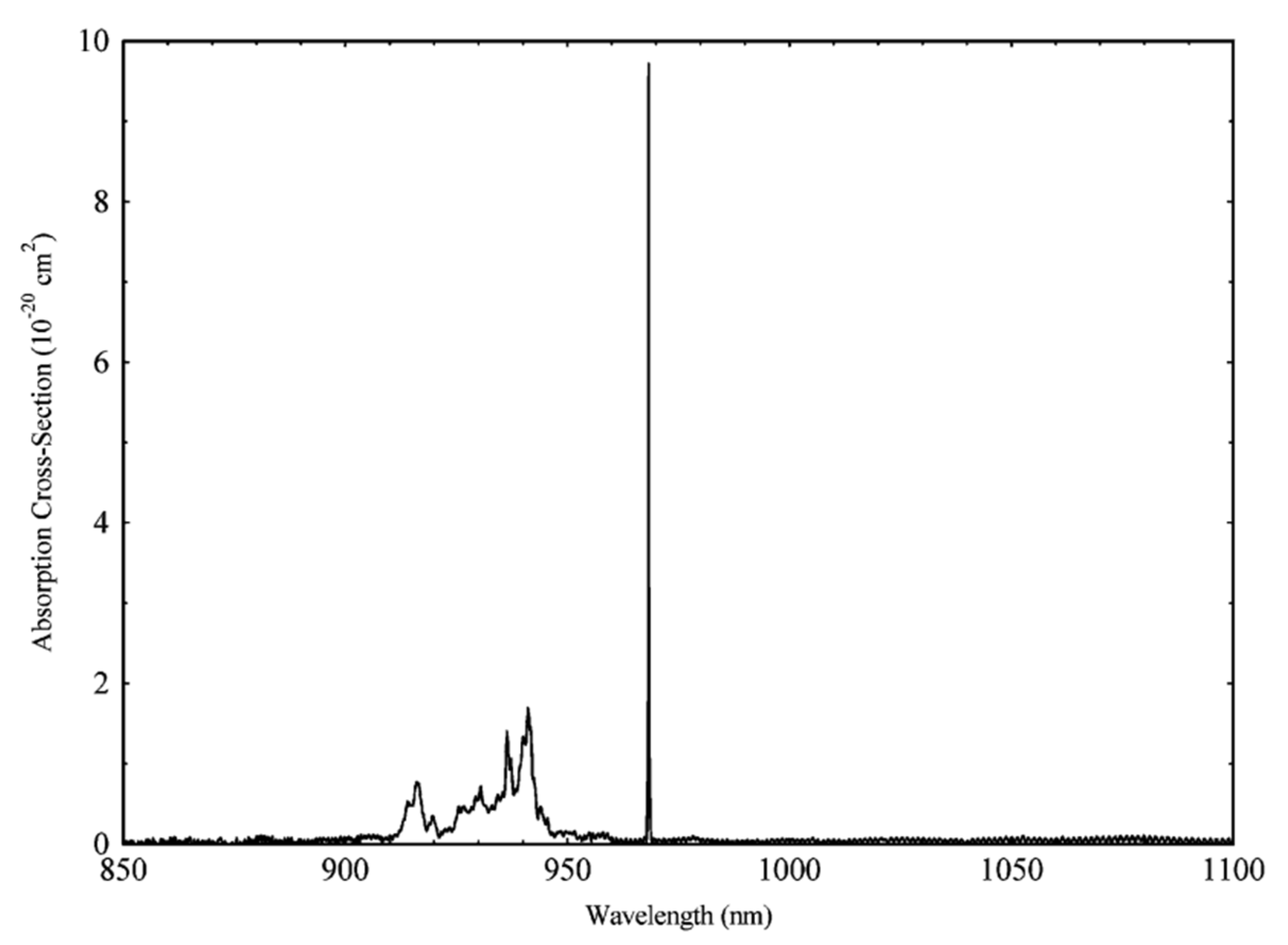
2.2. Spectral Properties

In addition to thermodynamic properties, spectral properties also change with temperature decrease. The researchers studied the absorption bandwidth, absorption cross-section, emission cross-section, fluorescence lifetime, and other properties of Yb:YAG crystals.
Figure 2 and Figure 3 show the comparison of the absorption cross-section of Yb:YAG crystals (0.24 mm thick and 9.8% doping concentration) at 300 K and 75 K, respectively [12]. The X-axis is the wavelength, and the Y-axis is the emission cross-section. It can be seen from the figure that, as the temperature decreases, the absorption bandwidth at 940 nm narrows slightly, from about 18 nm at 300 K to about 13 nm at 75 K, but it is still much higher than the absorption bandwidth of Nd:YAG at 808 nm of about 2 nm. The wide absorption bandwidth means fewer requirements for temperature control and wavelength stability of the pump source, which contributes to reducing costs. Additionally, then the absorption cross-section is greatly increased, about twice that at 300 K at 75 K, which is beneficial to improving the pump absorption efficiency, reducing heat generation, and mitigating the degradation of beam quality due to thermal effects. The emission cross-section of the Yb:YAG crystal also increases significantly with the decrease in temperature [10]. The measured emission cross-section of Yb:YAG crystal (2% doping concentration) at 80 K is about 1.1 × 10⁻¹⁹ cm2. It is about 5 times that of room temperature, which greatly improves the laser gain, improves the energy extraction efficiency, and can reduce the demand for pump power, thereby reducing the possibility of thermal effects and crystal damage. However, at the same time, the emission spectrum width of the Yb:YAG crystal becomes narrow, due to the limitation of the time-bandwidth product, the narrowing of the spectral width results in a larger pulse width limit, which makes the pulse compression more difficult and limits the pulse width to the picosecond level [15]. The results of research on the fluorescence lifetime of Yb:YAG crystals show that with the decrease in temperature, the fluorescence lifetime of Yb:YAG crystals decreases slightly and remains at about 1 ms [15]. Although the fluorescence lifetime decreases with the increase in doping concentration, it does not have a significant effect on the energy storage capacity of the crystal for low doping concentration.
In addition, Yb:YAG has a quasi-three-level structure, and there is a thermal particle number distribution of about 5.3% in the lower energy level at room temperature. Therefore, there is a serious self-absorption effect, resulting in a high pump threshold and a small effective emission cross-section. As shown in Figure 4, when the Yb:YAG crystal is cooled to 77 K, the proportion of particles in the lower energy level drops to the order of 10−5, and the crystal transforms into a four-level structure, which effectively reduces the pumping threshold, increases the pumping efficiency, and increases the effective emission cross-section [8,9].
To summarize, the changes in various properties of Yb:YAG crystals at low temperatures reduce the decrease in beam quality caused by thermal effect, decrease the difficulty of heat conduction, decrease the pumping threshold, increase the pumping efficiency, increase the energy storage capacity, and increase the laser gain, which makes Yb:YAG crystals at low temperatures very suitable as gain media for high-power solid-state lasers.

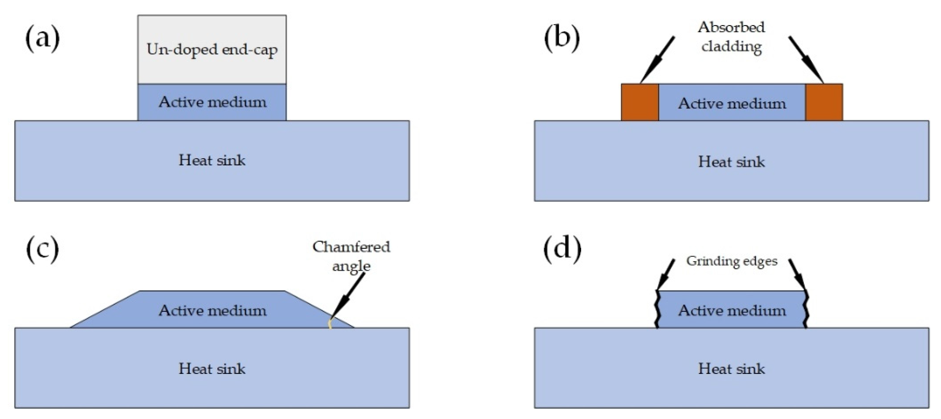
3. Suppression of ASE Effect

With the decrease in temperature, the emission cross-section of Yb:YAG crystals increases sharply, which brings beneficial changes such as increasing the laser gain and increasing the extraction efficiency on the one hand, and increased probability of spontaneous emission and aggravated ASE effect, on the other. As a result, a large number of inversion particles are consumed, and the efficiency of the laser is reduced. Therefore, how to suppress the ASE effect has become an important topic in the study of cryogenically cooled Yb:YAG lasers. As shown in Figure 5, in the existing cryogenically cooled Yb:YAG high-power laser, the ASE effect is suppressed by bonding undoped YAG crystal and absorber (Cr4+:YAG crystal) cladding, and there are also traditional methods such as chamfering edges and grinding around the edges [16,17,18,19].
As shown in Figure 5a, a layer of YAG crystal is bonded on the surface of the Yb:YAG crystal. Since the two refractive indices are the same, photons larger than the total reflection angle of the interface are introduced into the YAG crystal. The YAG crystal has no gain, and photons decay rapidly in it, thereby reducing the ASE effect [16]. If no suppression measures are taken, ASE photons are reflected on the side of the gain medium and return to the gain medium, in which they are amplified again and even form parasitic oscillations, in order to prevent ASE photons from being reflected back. As shown in Figure 5b, a layer of Cr4+:YAG crystal is wrapped around the Yb:YAG crystal as an absorber for absorbing ASE photons [17]. In addition, by changing the shape of the side of the gain medium, such as by edge chamfering [18], as shown in Figure 5c, and edge grinding [19], as shown in Figure 5d, the ASE photons are refracted out of the crystal so that they can no longer be amplified, which also suppresses the ASE effect.

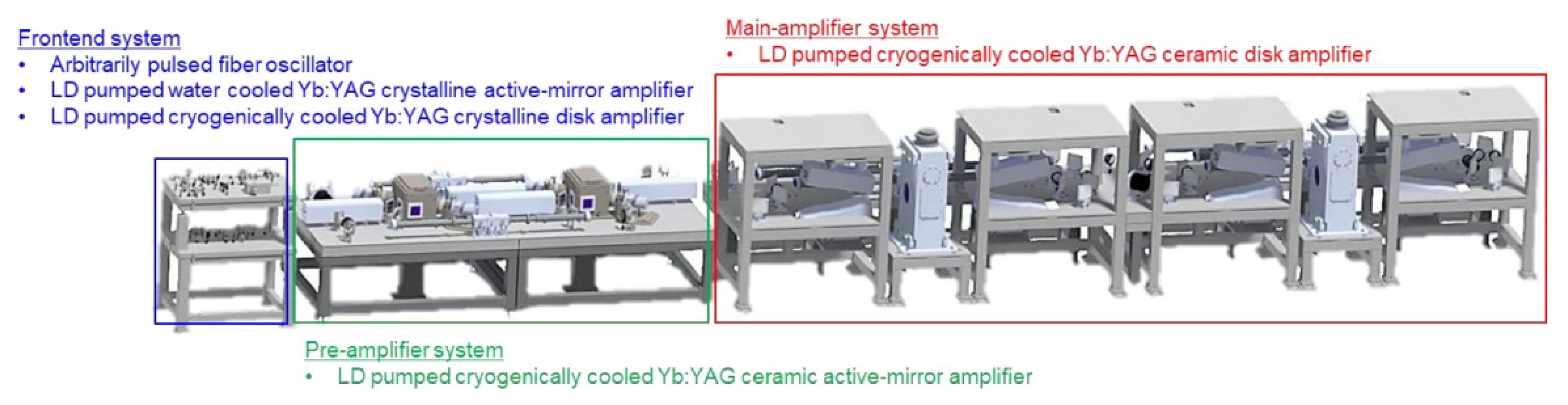
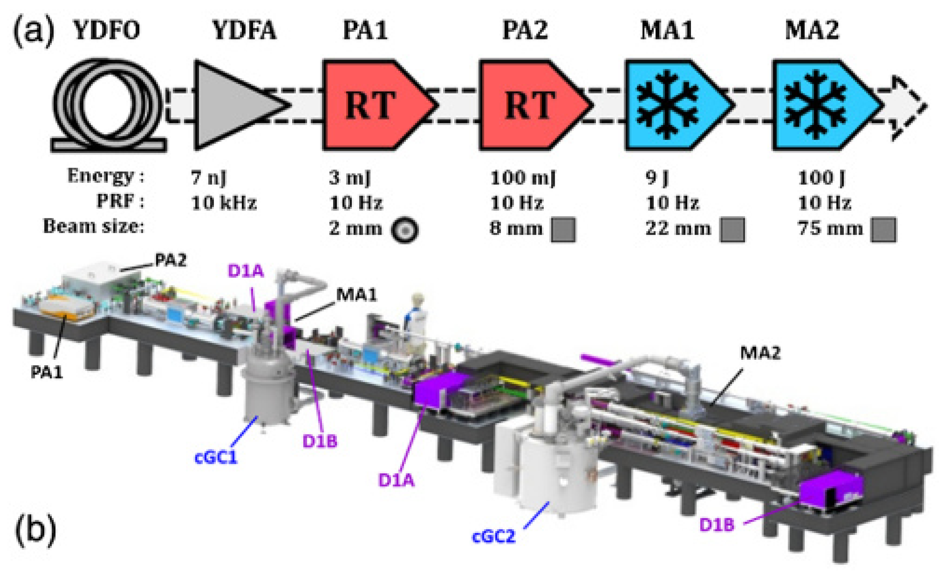
4. Cryogenically Cooled Yb:YAG Lasers

In China, research institutions such as the Chinese Academy of Sciences and the Chinese Academy of Engineering Physics have carried out research on cryogenically cooled high-power short-pulse Yb:YAG lasers, but due to the late start of the research, the reported laser power in the literature only reaches the order of tens of watts [8,19,20]. The world’s leading research institutions have achieved kilowatt-level output in both 10 Hz nanosecond lasers and 1 kHz picosecond lasers. The following sections discuss landmark achievements of cryogenically cooled high-power short-pulse Yb:YAG lasers around the globe.

4.1. High-Energy Nanosecond Laser

Since the beginning of the new century, high-energy nanosecond solid-state lasers with a repetition frequency of more than 10 Hz and pulse energy of more than 10 J have developed vigorously [21]. There is an urgent need in the fields of laser-confined nuclear fusion [22], high-energy physics research [23], and X-ray sources [24]. Such laser systems have been built in many countries, such as the United Kingdom (DiPOLE [25]), France (LUCIA [26]), the United States (Mercury [27], HAPLS [28], etc.), Japan (CcAMA [29], HALNA [30], Hamamatsu [31], etc.). In China, Tsinghua University [32], Chinese Academy of Engineering Physics [33], Chinese Academy of Sciences Institute of Optoelectronics [34], and other institutions have relevant research results. Systems such as Hamamatsu and CcAMA in Japan and DiPOLE in the United Kingdom use cryogenically cooled Yb:YAG crystals as the gain media of the main amplifier. In 2017, the DiPOLE system in the United Kingdom reported the highest index of high-energy nanosecond lasers so far [25] (105 J, 10 Hz, 10 ns), also the first kilowatt-class system.
Hamamatsu of Japan reported a 117 J, 0.05 Hz laser output in 2019 [35]; the system structure is shown in Figure 6 [31]. The front end of the system outputs 5 J, 40 ns, 0.05 Hz seed light, which is amplified by the preamplification stage and the main amplifying stage to amplify the pulse energy to 28 J and 117 J, respectively. The preamplification stage is an active mirror configuration, the cooling temperature is 100 K, and the injection pump energy exceeds 80 J. The main amplifying stage is two double-pass amplification modules with a lamination configuration, each module is composed of six pieces of Yb:YAG crystals with a diameter of 120 mm and a thickness of 10 mm. The gain medium is cooled with helium gas, the helium gas pressure is adjustable from 1 atm to 5 atm, and the temperature is adjustable from 150 K to 300 K. A 7 mm thick Cr4+:YAG crystal is bonded around the Yb:YAG crystal to suppress the ASE effect, and gradient doping with atomic doping concentrations of 0.5%, 0.7%, and 1.0% is used to homogenize the absorption. When 895 J of pump energy was injected, pulse energy of 117 J was obtained, and the optical efficiency was 12.5%. Its pump source has a 10 Hz output capability, so its next goal is to increase the repetition frequency to 10 Hz.
Osaka University reported in 2021 that its CcAMA system achieved a 9.3 J, 33.3 Hz laser output [29]. The system consists of a seed source, a preamplification stage, and a main amplifying stage. The structure of the main amplifying stage is shown in Figure 7. The single, longitudinal-mode fiber seed source used has an output power of 5 mW. The preamplification stage consists of a regenerative amplifier and a rod-shaped multipass amplifier. The temperature of the cooling medium is 77 K, the output energy is 285 mJ, and the repetition frequency is 1–100 Hz. The main amplifying stage adopts a lamination configuration, and the gain medium is composed of four Yb:YAG crystals with a diameter of 45 mm and a thickness of 7 mm. The crystal is surrounded by 7.5 mm thick Cr4+:YAG and is pumped by two LD arrays with a peak power of 50 kW. The laser passes through the gain medium twice for amplification (one amplification is defined here as being reflected twice through the gain medium by the reflective layer). Osaka University focused on the analysis of the heat dissipation process, pointing out that active mirror configuration is not suitable for high repetition frequency operation, and improved the cooling method of the main amplifying stage by adding a molybdenum film between the crystal and the heat sink to reduce stress. The heat sink is flow-cooled using 78 K liquid nitrogen. The system achieved 10 J, 20 Hz stable operation for more than one minute, but when the repetition rate increased to 33.3 Hz, the pulse energy decreased, and the average energy for 20 s was 9.3 J. After calculation, when the device ran at 100 Hz, the working temperature was 116 K. In order to achieve 10 J, 100 Hz laser output, it is necessary to further improve the cooling performance to reduce the working temperature to below 100 K.
The DiPOLE system in the United Kingdom reported a laser output of 105 J, 10 Hz, 10 ns in 2017 [25], setting a world record for the average power of nanosecond lasers, which has not been broken so far. The configuration of the DiPOLE system is shown in Figure 8. It consists of a front end, a 10 J main amplifying stage, and a 100 J main amplifying stage. The 10 J main amplifying stage was reported in 2015 and can achieve a 10.8 J, 10 Hz laser output [36].
The front end is composed of a fiber seed source, regenerative amplifier, and multipass amplifier [37]. The output of the continuous oscillator is chopped by an acousto-optic modulator into a 10 kHz, 150 ns pulse output, which is amplified by a multistage fiber and modulated by an electro-optic modulator, to output a 7 nJ, 10 ns pulse seed. In the regenerative amplifier, a Pockels cell is used to select a pulse with a repetition rate of 10 Hz from the 10 kHz repetition rate pulse. After about 170 round trips in the cavity, the pulse energy is amplified to 4.5 mJ. A Gaussian beam with a diameter of 2 mm is passed through a beam shaper, a sawtooth aperture, and a spatial filter. The beam is adjusted to a square super-Gaussian beam with a side length of 8 mm, and the pulse energy is reduced. The multipass amplifier uses a 1.8 kW pump source, the beam passes through the gain medium 8 times, and the pulse energy is amplified to 100 mJ. After feedback isolation and shaping, the light beam becomes a square light spot with a side length of 22 mm.
The 10 J main amplifying stage adopts a lamination configuration [36], consisting of fpir bonded crystals with a diameter of 55 mm and a thickness of 5 mm. The space between sheets is 1.5 mm, and 150 K helium gas is charged at 35 m3/h for cooling. The center of the crystal is a Yb:YAG crystal with a diameter of 45 mm, and the periphery is surrounded by a 5 mm wide Cr4+:YAG crystal to suppress the ASE effect. Gradient doping is used, with atomic doping concentrations of 1.1% and 2.0% from the two sides to the middle, respectively, to homogenize the pump absorption. The crystal is pumped by two 940 nm LD arrays with a peak power of 29 kW with a typical pump pulse width of 1 ms. Under the injection of 48 J pump energy, 10.8 J pulse energy can be obtained, and the optical efficiency is 22.5%. The polarization state of the output laser is adjusted to match the pump light of the 100 J main amplifier stage. After feedback isolation and beam expansion, the side length of the light spot becomes 75 mm to ensure that the output flux is less than 2 J/cm2.
The 100 J main amplifying stage also adopts a lamination configuration [37], which is composed of six bonded crystals with an interval of 2 mm and 8.5 mm thick. Gradient doping is also used, and the atomic doping concentrations from the two sides to the middle are 0.4%, 0.6%, and 1.0%, respectively. Two pump sources are used, with a peak power of 250 kW to pump, the pump pulse width is 1.2 ms, and the pump spot is a square spot with a side length of 79 mm. Its cooling system has a cooling capacity of 6 kW, and the rated operating state of helium gas is a mass flow rate of 135 ± 5 g/s, a temperature of 150 ± 0.5 K, and a pressure of 10 bar. Under the condition of pre-stage injection pulse energy of 6 J and pump energy of 465 J, the output of 105 J, 10 Hz, and 10 ns was achieved.
The team reported a second 100 J-class laser system (DiPOLE100X) [38] in 2018, with an improved layout from a straight line to a “U” shape, making it more compact. Four future development goals were proposed: the repetition rate was extended to 100 Hz; the pulse energy was increased to 150 J; the frequency conversion to the visible light band (frequency doubling 515 nm) and the ultraviolet light band (frequency doubling 343 nm) was realized, and the system size was reduced.

4.2. High-Energy Picosecond Laser

High-energy short-pulse lasers with high repetition rates can be used to drive ultrafast coherent short wavelength radiation sources [39], drive high repetition frequency high-average power femtosecond lasers, and serve as secondary sources of high-flux high-energy particles [40] and photons [41]. In addition, 100 Hz picosecond Joule lasers have been used to pump soft X-ray lasers [42]. Short-pulse lasers with a repetition frequency of 1 kHz or more and peak power of 1 TW can form a continuous plasma channel in the atmosphere [43], which can be used for laser-induced water condensation [44], remote pollution monitoring [45], light through fog communication [46], laser-induced lightning [47], etc. The above applications make 1 kHz, 1 J kilowatt-level picosecond lasers a common research goal of research institutions in various countries.
TRUMPF is oriented to the application of forming plasma channels in the atmosphere, using the Yb:YAG crystal at room temperature as the gain medium, and using the chirped pulse amplification technology to achieve a laser output of 720 mJ, 1 kHz, less than 1 ps in 2020 [48]. The schematic diagram is shown in Figure 9, which consists of a seed laser, a regenerative amplifier, two multipass amplifiers, and a compressor.
The seed laser delivers femtosecond pulses with a pulse energy of 100 µJ and a repetition rate of 1 kHz. The seed laser has excellent beam quality of M2 = 1.15. The pulse is stretched to a duration of 1 ns with a chirped fiber Bragg grating (CFBG). The regenerative amplifier is pumped by laser diodes with 1 kW average pump power. Within multiple resonator roundtrips, the pulse energy is amplified to 240 mJ, while maintaining a beam quality with M2 < 1.2.
The multipass amplifier comprises four industrial thin-disk laser heads. To minimize the thermal load on the disks, the disks are pumped with a duty cycle of 25%, at the pulse repetition rate of 1 kHz. Each disk is pumped with an average power of 2.3 kW. The super-Gaussian-shaped pump spot has a diameter of approximately 12 mm. The cumulated total average pump power is >9 kW for the four amplifier heads, which is efficiently absorbed in the water-cooled disks, even without optical energy extraction. In the first stage, the pulses are amplified from 240 mJ to 550 mJ using seven passes distributed on the two laser heads. In the second stage, the pulse energy is increased to 800 mJ via four additional disk reflections distributed on the laser heads 3 and 4 while maintaining a beam quality with M2 < 1.6.
The output pulses are compressed by a pair of multilayer dielectric (MLD) reflection gratings, arranged in a Treacy-type configuration under a near-Littrow angle of incidence. The diffraction efficiency of each of the gratings is about 97%, leading to an overall compressor efficiency of ∼90%. At the full output power of the multipass amplifier (800 W uncompressed), 720 W average power was measured after compression, corresponding to a pulse energy of 720 mJ. After compression, the beam quality increased to M2 < 2.1.
The advantage of Yb:YAG crystal operating at room temperature is that the emission spectral width is wide and small pulse width can be achieved, but its thermodynamic properties make it difficult to manage thermal effects at room temperature, resulting in poor beam quality, and its spectral properties lead to lower pump absorption efficiency, lower gain, and lower energy extraction efficiency, and it is difficult to obtain larger pulse energy.
The University of Colorado reported in 2016 that an active-mirror configuration laser using a cryogenically cooled Yb:YAG crystal as a gain medium produced a 1 J, 500 Hz, 3.8 ps laser output [49] and obtained a 1 J, 1 kHz laser output before compression in 2018 [50]. In 2019, DESY in Germany reported the use of a cryogenically cooled Yb:YAG laser to generate a 1 J, 500 Hz, 20 ns laser output, and predicted that its pulse width could be compressed to 5 ps [51]. In 2020, the University of Colorado in the United States used diode-pumped chirped pulse amplification technology, using a cryogenically cooled Yb:YAG crystal as the gain medium, and obtained a laser output of 1.1 J, 1 kHz, and 4.5 ps [52], which is the highest single-pulse energy achieved by a kilohertz picosecond laser to date. The system configuration is shown in Figure 10, which consists of a front end and two cryogenically cooled Yb:YAG amplifiers.
The front end consists of a mode-locked oscillator, a pulse stretcher, and a regenerative amplifier. The Yb:KYW oscillator outputs a 10 nJ, 55 MHz, 200 fs pulse, which is stretched to 270 ps via a 1740 lines/mm grating while adjusting the stretcher to select a spectral bandwidth that matches the peak gain region of the subsequent Yb:YAG crystal. The regenerative amplifier works at room temperature, using a Yb:YAG crystal with a thickness of 0.5 mm and an atomic doping concentration of 7% as the gain medium, and is cooled by a water-cooled copper heat sink. A fiber-coupled laser diode was used as the pump source, the pump power was 60 W, the pump wavelength was 969 nm, the pump pulse width was 500 μs, and the pump light diameter was 1 mm. The resonator design enables the seed light to pass through the gain medium four times per round trip, amplifying the pulse energy from about 1 nJ to 2 mJ, and the Pockels cell selects a pulse repetition frequency of 1 kHz. After output from the regenerative amplifier, the beam passes through a spatial filter, a Pockels cell, and a pair of orthogonal polarizers to improve beam quality and pulse contrast and achieve feedback isolation.
The preamplifier operates at low temperature, using two 5 mm thick Yb:YAG crystals with 2% atomic doping concentration as the gain medium. Both crystals are placed in a vacuum chamber to avoid condensation forming on the crystals, and the back is cooled by liquid nitrogen. Each crystal is pumped by a fiber-coupled laser diode, the pump power is 400 W, the pump wavelength is 940 nm, the pump pulse width is 450 μs, and the pump light diameter is 4 mm. Through optical path design, the laser is amplified five times in the first crystal (one amplification is defined as being reflected by the reflective layer and passing through the gain medium twice) and then amplified twice in the second crystal. The pulse energy was amplified from millijoules to 100 mJ. The laser output from the preamplifier passes through a sawtooth aperture with a diameter of 8 mm to achieve a flat-top spot distribution, and the feedback is isolated by a Faraday rotator and a pair of orthogonal polarizers.
The main amplifier also operates at a low temperature and consists of two bonded crystals placed in a vacuum chamber. The central area of each crystal is a square Yb:YAG crystal with a side length of 30 mm, a thickness of 2 mm, and an atomic doping concentration of 3%, surrounded by 10 mm wide Cr4+:YAG crystal cladding to suppress the ASE effect and parasitic oscillation, and the front surface is bonded to a 3 mm thick undoped YAG crystal to suppress the ASE effect and provide structural support. The front and rear surfaces are, respectively, coated with high transmission/high reflection coatings with wavelengths of 940–1030 nm. Each crystal is pumped by a laser diode array with a pump power of 6000 W, a pump wavelength of 940 nm, a pump pulse width of 380 μs, and a pump spot diameter of 16 mm. The pump light is reflected by the spherical mirror and passes through the gain area several times so that the total absorption rate of the pump light is greater than 90%, which can reduce the doping concentration and prevent the thermal conductivity of the Yb:YAG crystal from being too small at low temperature, which affects the thermal effect management [11]. The system is cooled by liquid nitrogen, and the crystal temperature is kept below 130 K under the maximum pump power. The difference in crystal temperature with and without laser extraction was compared, and the crystal temperature increased by about 8 K without laser extraction. The optical path design makes the laser pass through the gain medium four times, and the laser is amplified eight times through the two crystals. When the pump injection energy is 3.5 J, the 70 mJ seed injected by the preamplifier is amplified to a maximum of 1.26 J, and the optical efficiency is about 36%. In 25,000 shots, the average pulse energy is 1.2 J, and the beam quality M2 in the two directions is 1.32 and 1.39, respectively.
Due to the narrowing of the gain, the full width at half maximum (FWHM) of the output spectrum of the main amplifier is 0.35 nm. Due to the limitation of the transformation limit, the maximum pulse width after compression is 3.9 ps. After amplification, the beam is expanded, collimated, and injected into the compressor. In order to prevent damage to the grating, the diameter of the light spot is about 40 mm, and 1740 lines/mm grating is used to compress the pulse width to 4.48 ps. The mirrors are all coated with a high reflection coating of 1030 nm, which makes the overall compression efficiency greater than 90%, and the pulse energy after compression is 1.1 J. The resulting 1.1 J, 1 kHz, 4.5 ps laser output has been used to generate high-energy femtosecond laser pulses at a kHz repetition rate.

5. Discussion

The average power of 1 kW is a tacit research goal formed by various research institutions. Thus far, laser outputs of 105 J, 10 Hz, 10 ns, and 1.1 J, 1 kHz, 4.5 ps have been achieved, all of which have exceeded the milestone of 1 kw. Through the analysis of the thermodynamic and spectral properties of Yb:YAG at low temperatures, it was revealed that Yb:YAG crystals have great development potential for laser power improvement. The two laser systems that maintain the highest index also use Yb:YAG crystals as the gain medium at low temperatures. For high-power nanosecond lasers, the goal of the British DiPOLE system is set at a single pulse energy of 1 kJ [36], and the pursuit of larger pulse energy, higher repetition frequency, and more compact laser configuration should be the mainstream development direction in the future; as regards high-power picosecond lasers, the pulse width is limited to about 5 ps due to the transformation limit. In order to pursue the peak power above 1 TW, the single-pulse energy needs to be increased to 5 J. Therefore, how to realize the laser output of 5 J, 1 kHz, and 5 ps will be key research topics for research institutions.

Author Contributions

Conceptualization, Z.F. and Z.B.; investigation, Y.S. and M.Y.; writing—original draft preparation, Y.S.; writing—review and editing, Z.B.; supervision, Z.F. All authors have read and agreed to the published version of the manuscript.

Funding

This study was supported by the Guangdong Key Research and Development Program (2018B090904003).

Institutional Review Board Statement

Not applicable.

Informed Consent Statement

Not applicable.

Data Availability Statement

The study did not report any data.

Conflicts of Interest

The authors declare no conflict of interest.

References

  1. Johnson, L.F.; Geusic, J.E.; Uitert, L.V. Coherent oscillations from tm3+, ho3+, yb3+ and er3+ ions in yttrium aluminum garnet. Appl. Phys. Lett. 1965, 7, 127–129. [Google Scholar] [CrossRef]
  2. Wang, X.D. Research on Diode Pumped Thin Disk Laser. Master’s Thesis, Changchun University of Science And Technology, Changchun, China, December 2015. [Google Scholar]
  3. Wang, S.Q.; Li, Y.L.; Li, S.M.; Bai, C.C.; Wang, Y.B.; Lei, Y. Research progress of LD pumped Yb:YAG solid-state laser. Jiguang Yu Hongwai 2018, 48, 3–9. [Google Scholar]
  4. Fan, T.Y. Heat generation in Nd:YAG and Yb:YAG. IEEE J. Quantum Electron. 1993, 29, 1457–1459. [Google Scholar] [CrossRef]
  5. Wang, P.F.; Zhang, D.; Lv, B.D. Recent advances of diode-pumped thin disc-laser. Jiguang Jishu 2003, 6, 551–553+566. [Google Scholar]
  6. Chenais, S.; Druon, F.; Forget, S.; Balembois, F.; Georges, P. On thermal effects in solid state lasers: The case of ytterbium-doped materials. Prog. Quantum Electron. 2009, 30, 89–153. [Google Scholar] [CrossRef] [Green Version]
  7. Zhang, Z.H.; Zhang, H.A. The relationship between the energy relaxation time and fluorescence radiation lifetime in three level system. Guangpuxue Yu Guangpu Fenxi 1989, 4, 1–4. [Google Scholar]
  8. Yan, X.W.; Jiang, X.Y.; Wang, Z.G.; Zheng, J.G.; Li, M.; Xiao, K.B. Cryogenic liquid-cooled Yb:YAG bulk amplifier. Zhongguo Jiguang 2019, 46, 59–64. [Google Scholar]
  9. Wang, X.D.; Gao, L.L.; Li, G. Research on characteristics of all-solid-state Yb:YAG disk laser. Ke Ji Feng 2015, 23, 3–4. [Google Scholar]
  10. Fan, T.Y.; Ripin, D.J.; Aggarwal, R.L.; Ochoa, J.R. Cryogenic Yb3+-doped solid-state lasers. IEEE J. Sel. Top. Quantum Electron. 2007, 13, 448–459. [Google Scholar] [CrossRef]
  11. Aggarwal, R.L.; Ripin, D.J.; Ochoa, J.R.; Fan, T.Y. Measurement of thermo-optic properties of Y3Al5O12, Lu3Al5O12, YAIO3, LiYF4, LiLuF4, BaY2F8, KGd(WO4)2, and KY(WO4)2 laser crystals in the 80–300 K temperature range. J. Appl. Phys. 2005, 98, 200. [Google Scholar] [CrossRef]
  12. Brown, D.C. The promise of cryogenic solid-state lasers. IEEE J. Sel. Top. Quantum Electron. 2005, 11, 587–599. [Google Scholar] [CrossRef]
  13. Koechner, W.; Sun, W. Solid-State Laser Engineering, 1st ed.; Science Press: Beijing, China, 2022; pp. 356–405. [Google Scholar]
  14. Wu, W.M.; Wu, H.Y.; Xu, X.J.; Guo, S.F. Cryogenically Cooled High Average Power Yb:YAG Laser. Jiguang Yu Guangdianzixuejinzhan 2010, 47, 42–47. [Google Scholar]
  15. Dong, J.; Bass, M.; Mao, Y. Dependence of the Yb3+ emission cross section and lifetime on temperature and concentration in yttrium aluminum garnet. J. Opt. Soc. Am. B 2003, 20, 1975–1979. [Google Scholar] [CrossRef]
  16. Peterson, P.; Gavrielides, A.; Newell, T.C.; Vretenar, N.; Latham, W.P. ASE in thin disk lasers: Theory and experiment. Opt. Express 2011, 19, 25672–25684. [Google Scholar] [CrossRef] [PubMed]
  17. Hua, S.; Wang, X.J. Amplified spontaneous emission in thin-disk lasers. In Solid State Lasers XXI: Technology and Devices; SPIE: Bellingham, WA, USA, 2012; pp. 370–377. [Google Scholar]
  18. Antognini, A.; Schuhmann, K.; Amaro, F.; Biraben, F.; Dax, A.; Giesen, A. Thin-Disk Yb:YAG Oscillator-Amplifier Laser, ASE, and Effective Yb:YAG Lifetime. IEEE J. Quantum Electron. 2009, 45, 993–1005. [Google Scholar] [CrossRef]
  19. Li, L.; Wang, J.L.; Cheng, X.J.; Liu, J.; Shi, X.C.; Chen, W.B. Cryogenic Yb:YAG solid state pulsed laser amplifier. Hongwai Yu Jiguagngongcheng 2013, 42, 1170–1173. [Google Scholar]
  20. Wang, M.Z.; Duan, W.T.; Cao, D.X.; Zheng, J.G.; Jiang, X.Y.; Li, M.Z.; Tan, J.C.; Yu, H.W.; Jing, F. Laser diode pumped cryogenically cooled Yb:YAG laser design for rep-rated high-energy output. Qiangjiguang Yu Lizishu 2010, 22, 36–40. [Google Scholar]
  21. Fu, X.; Liu, T.H.; Lei, X.X.; Liu, Q. High energy diode-pumped rep-rated nanosecond solid-state laser. Zhongguo Jiguang 2021, 48, 45–65. [Google Scholar]
  22. Wang, M. Recent Progress of Laser Diode-Pumped Solid-State Laser Drivers for Inertial Fusion Energy. Jiguang Yu Guangdianzixuejinzhan 2008, 45, 56–63. [Google Scholar]
  23. Drake, R.P. A journey through high-energy-density physics. Nucl. Fusion 2019, 59, 035001. [Google Scholar] [CrossRef]
  24. Perry, M.D.; Sefcik, J.A.; Cowan, T.; Hatchett, S.; Hunt, A.; Moran, M.; Pennington, D.; Snavely, R.; Wilks, S.C. Hard X-ray production from high intensity laser solid interactions (invited). Rev. Sci. Instrum. 1999, 70, 265–269. [Google Scholar] [CrossRef]
  25. Mason, P.; Martin, D.; Ertel, K.; Jan, P.; Butcher, T.; Martin, H. Kilowatt average power 100 J-level diode pumped solid state laser. Optica 2017, 4, 438–439. [Google Scholar] [CrossRef]
  26. Novo, T.; Albach, D.; Vincent, B. From 10 to 30 joules with the Lucia laser system: Update on current performance and cryogenic amplifier development. In Proceedings of the 2013 Conference on Lasers and Electro-optics (CLEO), San Jose, CA, USA, 9–14 June 2013. [Google Scholar]
  27. Bayramian, A.; Armstrong, J.; Beer, G. High-average-power femto-petawatt laser pumped by the Mercury laser facility. J. Opt. Soc. Am. B 2008, 25, B57–B61. [Google Scholar] [CrossRef]
  28. Korn, G.; Silva, L.O.; Haefner, C.L. High average power, diode pumped petawatt laser systems: A new generation of lasers enabling precision science and commercial applications. Proc. SPIE 2017, 10241, 1024102. [Google Scholar]
  29. Ogino, J.; Tokita, S.; Kitajima, S.; Yoshida, H.; Kawanaka, J. 10 J operation of conductive-cooled Yb:YAG active-mirror amplifier and prospects for 100 Hz operation. Opt. Lett. 2020, 46, 621–624. [Google Scholar] [CrossRef]
  30. Yasuhara, R.; Kawashima, T.; Sekine, T. 213 W average power of 2.4 GW pulsed thermally controlled Nd:glass zigzag slab laser with a stimulated Brillouin scattering mirror. Opt. Lett. 2009, 33, 1711–1713. [Google Scholar] [CrossRef]
  31. Sekine, T.; Kurita, T.; Kurata, M. Development of a 100-J DPSSL as a laser processing platform in the TACMI consortium. High Energy Density Phys. 2020, 36, 100800. [Google Scholar] [CrossRef]
  32. Liu, T.H.; Feng, T.; Sui, Z.; Liu, Q.; Gong, M.L.; Zhang, L.; Jiang, B.X.; Fu, X. 50 mm-aperture Nd:LuAG ceramic nanosecond laser amplifier producing 10 J at 10 Hz. Opt. Express 2019, 27, 15595–15603. [Google Scholar] [CrossRef]
  33. Jiang, X.; Wang, Z.; Yan, X. LD end-pumped 12J-10Hz Nd:YAG pulse laser. Proc. SPIE 2019, 11333, 113330M. [Google Scholar]
  34. Fan, Z.W.; Qiu, J.S.; Kang, Z.J.; Chen, Y.Z.; Tang, X.X. High beam quality 5 J, 200 Hz Nd:YAG laser system. Light Sci. Appl. 2017, 6, e17004. [Google Scholar] [CrossRef] [Green Version]
  35. Kurata, M.; Sekine, T.; Hatano, Y.; Muramatsu, Y.; Kawanaka, J. Development of a 100 J Class Cryogenically Cooled Multi-disk Yb:YAG Ceramics Laser. In Advanced Solid State Lasers; Optical Society of America: Washington, DC, USA, 2019. [Google Scholar]
  36. Banerjee, S.; Ertel, K.; Mason, P.D. DiPOLE: A 10 J, 10 Hz cryogenic gas cooled multi-slab nanosecond Yb:YAG laser. Opt. Express 2015, 23, 19542–19551. [Google Scholar] [CrossRef] [PubMed]
  37. Mason, P.D.; Banerjee, S.; Ertel, K. DiPOLE100: A 100 J, 10 Hz DPSSL using cryogenic gas cooled Yb:YAG multi slab amplifier technology. In High-Power, High-Energy, and High-Intensity Laser Technology II; International Society for Optics and Photonics: Bellingham, WA, USA, 2015. [Google Scholar]
  38. Mason, P.D.; Banerjee, S.; Smith, J. Development of a 100 J, 10 Hz laser for compression experiments at the High Energy Density instrument at the European XFEL. High Power Laser Sci. Eng. 2018, 6, e65. [Google Scholar] [CrossRef] [Green Version]
  39. Reagan, B.A.; Berrill, M.; Wernsing, K.A. High-average-power, 100-Hz-repetition-rate, tabletop soft-x-ray lasers at sub-15-nm wavelengths. Phys. Rev. A 2014, 89, 381–397. [Google Scholar] [CrossRef] [Green Version]
  40. Salehi, F.; Goers, A.J.; Hine, G.A. MeV electron acceleration at 1 kHz with <10 mJ laser pulses. Opt. Lett. 2016, 42, 215–218. [Google Scholar] [CrossRef] [PubMed]
  41. Hollinger, R.; Bargsten, C.; Shlyaptsev, V.N. Efficient picosecond x-ray pulse generation from plasmas in the radiation dominated regime. Optica 2017, 4, 1344. [Google Scholar] [CrossRef]
  42. Reagan, B.A.; Wernsing, K.A.; Curtis, A.H. Demonstration of a 100 Hz repetition rate gain-saturated diode-pumped table-top soft X-ray laser. Opt. Lett. 2012, 37, 3624–3626. [Google Scholar] [CrossRef] [Green Version]
  43. Braun, A.; Korn, G.; Liu, X.; Du, D.; Mourou, G. Self-channeling of high-peak-power femtosecond laser pulses in air. Opt. Lett. 1995, 20, 73–75. [Google Scholar] [CrossRef]
  44. Rohwetter, P.; Kasparian, J.; Stelmaszczyk, K. Laser-induced water condensation in air. Nat. Photonics 2010, 4, 254–270. [Google Scholar] [CrossRef]
  45. Kasparian, J.; Rodriguez, M.; Mejean, G.; Yu, J.; Salmon, E.; Wille, H. White-light filaments for atmospheric analysis. Science 2003, 301, 61–64. [Google Scholar] [CrossRef]
  46. Schimmel, G.; Produit, T.; Mongin, D.; Kasparian, J.; Wolf, J.P. Free space laser telecommunication through fog. Optica 2018, 5, 1338. [Google Scholar] [CrossRef]
  47. Uchida, S.; Shigeaki, Y.; Shimada, H. Laser-triggered lightning in field experiments. J. Opt. Technol. 1999, 66, 199. [Google Scholar] [CrossRef]
  48. Herkommer, C.; Krtz, P.; Jung, R.; Klingebiel, S.; Metzger, T. Ultrafast thin-disk multipass amplifier with 720 mJ operating at kilohertz repetition rate for applications in atmospheric research. Opt. Express 2020, 28, 30164–30173. [Google Scholar] [CrossRef] [PubMed]
  49. Baumgarten, C.; Pedicone, M.; Bravo, H.; Wang, H.; Reagan, B.A. 1 J, 0.5 kHz repetition rate picosecond laser. Opt. Lett. 2016, 41, 3339–3342. [Google Scholar] [CrossRef] [PubMed]
  50. Areagan, B.; Baumgarten, C.; Jankowska, E. Scaling diode-pumped, high energy picosecond lasers to kilowatt average powers. High Power Laser Sci. Eng. 2018, 6, e11. [Google Scholar] [CrossRef] [Green Version]
  51. Zapata, L.E.; Schweisthal, S. Joule-Class 500 Hz Cryogenic Yb: YAG Chirped Pulse Amplifier. In Proceedings of the 2019 Conference on Lasers and Electro-Optics (CLEO), San Jose, CA, USA, 1 July 2019. [Google Scholar]
  52. Wang, Y.; Chi, H.; Baumgarten, C. 1.1 J Yb:YAG Picosecond Laser at 1 kHz Repetition Rate. Opt. Lett. 2020, 45, 6615–6618. [Google Scholar] [CrossRef] [PubMed]
Figure 1. Thermal conductivity, thermo-optic coefficient, and thermal expansion coefficient of YAG crystal as a function of temperature [10]. Reprinted/adapted with permission from Ref. [IEEE]. 2007, Tso Yee Fan.
Applsci 12 03711 g001
Figure 2. Absorption cross−section of Yb:YAG crystal (0.24 mm thick and 9.8% doping concentration) as a function of wavelength for a crystal temperature of 300 K [12]. Reprinted/adapted with permission from Ref. [IEEE]. 2005, D. C. Brown.
Applsci 12 03711 g002
Figure 3. Absorption cross−section of Yb:YAG crystal (0.24 mm thick and 9.8% doping concentration) as a function of wavelength for a crystal temperature of 75 K [12]. Reprinted/adapted with permission from Ref. [IEEE]. 2005, D. C. Brown.
Applsci 12 03711 g003
Figure 4. Thermal conductivity, thermo-optic coefficient, and thermal expansion coefficient of YAG crystal as a function of temperature.
Applsci 12 03711 g004
Figure 5. Methods to suppress ASE: (a) bonding undoped YAG crystals; (b) absorber cladding (Cr4+:YAG crystal); (c) edge chamfering; (d) edge grinding.
Applsci 12 03711 g005
Figure 6. Schematic diagram of the Hamamatsu system [31].
Applsci 12 03711 g006
Figure 7. System layout of a 10 J class Yb:YAG cryogenically cooled active-mirror amplifier. DFB, distributed feedback; EOM, electro-optic moderator; BE, beam expander; SA, serrated aperture; TFP, thin-film polarizer [29]. [Reprinted/Adapted] with permission from [ref #] © The Optical Society. OSA requires a special citation format.
Applsci 12 03711 g007
Figure 8. (a) Schematic of DiPOLE100 amplifier chain showing typical output performance after each amplifier stage, including free-space beam size and shape: YDFO = Yb-silica fiber oscillator; YDFA = Yb-silica fiber amplifier (inc. temporal pulse shaping); PA = room-temperature preamplifier (1 = Yb:CaF2 regenerative, 2 = Yb:YAG multi-pass); MA = main cryogenic amplifier (ceramic Yb:YAG multi-slab); (b) a 3D model of DiPOLE100 system: D = diode pumps; cGC = cryogenic gas coolers [25].
Applsci 12 03711 g008
Figure 9. (ad) Detailed sketch of the complete laser system. The seed pulses from the oscillator are stretched with a CFBG and first amplified by the regenerative amplifier, employing an industrial thin-disk laser head. The multipass contains 2 amplification stages, as indicated by the green (stage 1) and red (stage 2) areas. In each stage two industrial thin disk laser heads are employed. The grating compressor is set up in a folded Treacy-type near-Littrow configuration. TFP: Thin-film polarizer. HWP: Half-wave plate. BBO PC: BBO-based Pockels cell [48].
Applsci 12 03711 g009
Figure 10. Schematic diagram of the diode-pumped high energy CPA laser system: Regen, regenerative amplifier; SF, spatial filter; PC, Pockels cells; FCLD, fiber-coupled laser diodes; SA, serrated aperture; TFP, thin-film polarizer; P, periscope [52]. [Reprinted/Adapted] with permission from [ref #] © The Optical Society. OSA requires a special citation format.
Applsci 12 03711 g010
Publisher’s Note: MDPI stays neutral with regard to jurisdictional claims in published maps and institutional affiliations.

