Communication

High Repetition Rate, TEM00 Mode, Compact Sub-Nanosecond 532 nm Laser

1
Aerospace Information Research Institute, Chinese Academy of Sciences, Beijing 100094, China
2
School of Optoelectronic, University of Chinese Academy of Sciences, Beijing 100049, China
3
University of Chinese Academy of Sciences, Beijing 100049, China
4
HARGLO Applied Laser Technology Institute Co., Ltd., Tianjin 300000, China
5
Institute of Microelectronics of the Chinese Academy of Sciences, Beijing 100029, China
*
Author to whom correspondence should be addressed.
Appl. Sci. 2022, 12(9), 4428; https://doi.org/10.3390/app12094428
Submission received: 27 February 2022 / Revised: 19 April 2022 / Accepted: 24 April 2022 / Published: 27 April 2022
(This article belongs to the Special Issue Laser Technologies and Nonlinear Optics in Surface Sciences)

Abstract

:
As a critical transmitter, compact 532 nm lasers operating on high repetition and short pulse widths have been used widely for airborne or space-borne laser active remote sensing. We developed a free space pumped TEM00 mode sub-nanosecond 532 nm laser that occupied a volume of less than 125 mm × 50 mm × 40 mm (0.25 L). The fundamental 1064 nm laser consists of a passively Q-switched composite crystal microchip laser and an off-axis, two-pass power amplifier. The pump sources were two single-emitter semiconductor laser diodes (LD) with 808 nm wavelengths and a maximum continuous wave (CW) power of 10 W each. The average power of the fundamental 1064 nm laser was 1.26 W, with the laser operating at 16 kHz repetition rates and 857 ps pulse widths. Since the beam distortion would be severe in microchip lasers due to the increase in heat load, in order to obtain a high beam quality of 532 nm, the beam distortion in our experiment amplifying the fundamental laser was compensated by adjusting the distribution of the pumping beam. Furthermore, in the critical phase matching (CPM) regime for the second harmonic generation (SHG), a Type I LiB3O5 (LBO) crystal obtained 770 ps, a beam quality of M2 < 1.2, and a 16 kHz pulse output at 532 nm, which was better than 0.6 W average power.

1. Introduction

A compact sub-nanosecond microchip laser and an amplifier currently have applications in diverse areas including ranging and imaging, micromachining, material characterization, and environmental monitoring [1,2,3]. In particular, as transmitters, high repetition sub-nanosecond lasers have been used in photon-counting laser altimeters [4,5], or lidars, for high-resolution 2D profiles and/or 3D images of the underlying topography including soil, low-lying vegetation, water surfaces, human-made objects, ocean waves, shallow water bathymetry, 3D underwater imaging, etc. [6,7,8]. In a second-generation 3D imaging photon-counting lidar that can be installed in an Unmanned Aerial Vehicle (UAV) developed by Sigma Space Corporation, a compact laser transmitter can deliver a 142 mw, 700 ps, 532 nm beam at the maximum repetition rate of 22 kHz [9]. High beam quality is necessary because a Diffractive Optical Element (DOE) was used to split the 532 nm beam into a 10 × 10 array of beamlets with an 80% DOE efficiency.
In the photon-counting lidar, the laser should have the characteristics of high repetition rates, short pulse duration, and high beam quality to satisfy the need of measuring efficiency and precision. A microchip laser and a compact amplifier are ideal. Lincoln Laboratory reported passively Q-switched microchip lasers using Nd3+: YAG as the gain medium and fiber-pumped amplifiers that occupy a volume of less than 0.25 L. The compact laser has pulse widths between 150 ps and 3 ns, pulse energies up to 250 μJ at 1064 nm, and typical repetition rates between 4 and 20 kHz [2,3]. Isyanova, Y. et al. reported a compact satellite-ranging transmitter of SLR2000 consisting of a Cr4+: YAG passively Q-switched Nd: YAG microchip laser, an air-cooled Nd: YVO4 power amplifier, and a SHG module, which generated 532 nm, 470 mW, 270 ps pulses at a 2 kHz rate [10]. Manni, J. G reported a master oscillator power amplifier (MOPA) system that combines a 1064 nm microchip laser oscillator with a new diode-side-pumped Nd: YVO4 zig-zag slab amplifier. The 40 W pump power of the amplifier achieved a pulse energy of more than 800 μJ at a 2 kHz pulse rate [11]. Other schemes for high-repetition-rate microchip lasers have also been reported. Nicolaie, P. et al. reported an End-Pumped Composite Nd: YAG Laser Passively Q-switched by Cr4+: YAG, where the maximum average power was 4.2 W with the laser operating at a 24 kHz repetition rate and a 47.8 ns pulse duration (3.7 kW peak power) at a beam quality of M2 = 1.34 [12]. Pavel, N. et al. researched intracavity frequency doubling by employing a V-type laser resonator, which yielded 532 nm green pulses of 226 μJ energy and 86 ns width at 4.2 kHz [13].
Related to increasing the peak power of a microchip laser, much innovative progress has been reported by the Institute for Molecular Science based in Japan. Bhandari. R. et al. presented a microchip laser with a 1.9 MW peak power, 500 Hz, 550 ps, and 532 nm [14], which was pumped into the Quasi-Continuous Wave (QCW) regime by a fiber-coupled 120 W, 808 nm laser diode. Zheng, L. et al. reported a novel microchip laser using a high thermal conductivity gain media with the beam of 21.5 mJ pulse energy, 10 Hz, 1064 nm, and an M2 value between 10.7 and 11.8 [15]. Their research provided novel methods for the thermal restriction of microchip lasers, which would be expected in a high repetition rate.
As mentioned above, increasing the average power and the corresponding pulse energies of a sub-nanosecond laser with high repetition rates and high beam quality, which is an advantage of the detection distance and detection probability of lidar, is challenging in compact sizes.
This paper proposes a compact sub-nanosecond master oscillator power amplifier (MOPA) laser that combines a seed based on a microchip laser, an off-axis double-pass amplifier, and a SHG module. The key advantages are the following: the seed is a free-space-pumped microchip monolithic laser without a resonator optical alignment and a fiber-pumped structure; the average power and corresponding pulse energies were increased using a simple amplifier; and the beam distortion of the microchip was improved without a complicated optical-shaped system.
In our work, we first designed the experiments of a monolithic microchip laser, a two-pass Nd: YVO4 amplifier, and the SHG. In addition, the beam distortion was compensated by adjusting the fundamental amplifier’s distribution of pumping light so that it was elliptic. Then, according to the fundamental results, a 532 nm beam with properties better than 0.6 W, 770 ps, 37.5 μJ, 16 kHz, M2 < 1.2 was obtained by the Type I LBO crystal in the CPM regime for the SHG. Finally, we discussed the simulating results of generating a sub-nanosecond with the saturable absorber transmittance, the reflectivity of an output coupler, and the cavity length parameter, which can greatly aid in the design of a sub-nanosecond microchip laser with high repetition. On the basis of the research, we developed an engineering laser, whose laser head dimensions including the pump source are less than 125 mm × 50 mm × 40 mm.

2. Experimental Setup

A schematic diagram of the laser setup is shown in Figure 1. The sub-nanosecond laser consists of the microchip laser, the amplifier, and the SHG.

2.1. Sample Preparation

The seed laser medium was a YAG/Nd: YAG/Cr4+: YAG/YAG composite crystal (2 mm × 2 mm × 7 mm). The composite YAG/Nd: YAG/Cr4+: YAG/YAG crystal (Beijing Ke-Gang Electro-Optics Co., Ltd., Beijing, China) consists of two 1 mm-thick undoped YAG, a 3 mm-thick Nd: YAG (1.1 at. % Nd3+), and a 2 mm-thick Cr4+: YAG, which was used as a saturable absorber with 45% transmissions. The composite crystal was assembled by atomic diffusion bonding, and the roughness of the bonding surface should be less than 0.7 nm (PV). A composite crystal with undoped host crystal ends has been applied to high-performance diode-end-pumped lasers because the undoped segments bonded to the pumped face of an active segment serve as an effective heat sink that can reduce the rise in temperature on the pumped end surface and can effectively modulate the thermal uniformity [16]. For the same host crystal and thermal-expansion coefficients, the YAG was bonded with Nd: YAG or Cr4+: YAG; this process could be simplified and better stabilized through diffusion-bonding in high temperature more so than through hybrid crystal bonding in room temperature. Surface F1 was coated to be highly reflective at 1064 nm (>99.8%) and antireflective at 808 nm (<0.2%), while Surface F2 was an output coupler with 40% reflectivity at 1064 nm.

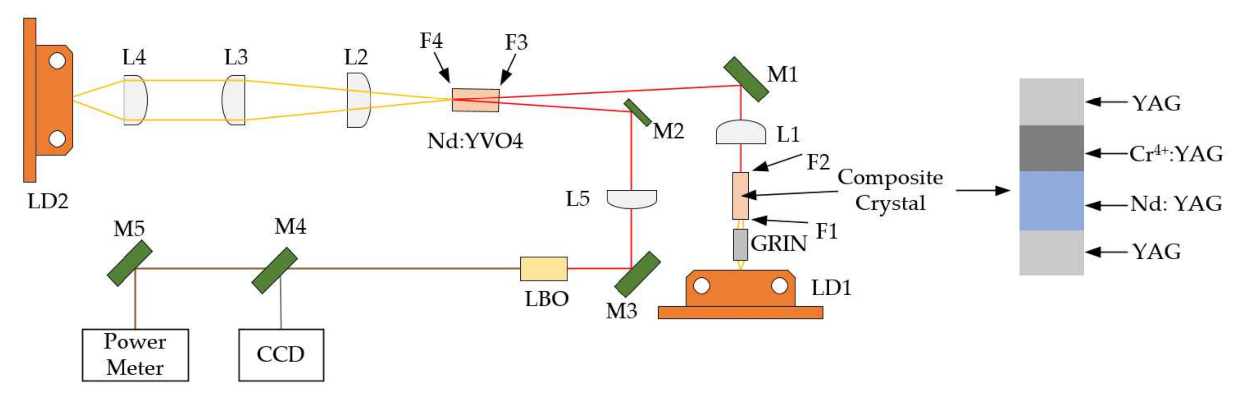
2.2. The Description of Experimental Setup

The seed was a diode end-pumped passively Q-switched monolithic microchip laser. The pump source was a single emitter semiconductor laser (LD1) with an 808 nm wavelength and a maximum CW of 10 W at 10 A current, and the electro-optical efficiency was about 50%. The emitting wavelength of the pump source was 808 nm at 25 °C. The fast-axis divergence and low-axis divergence were all 8° with fast-axis collimation (FAC). The heat sink of the pump source was attached to the TEC to help stabilize the pump wavelength. A gradient-index (GRIN) lens of 5 mm long was fixed between the LD1 and the composite crystal. L1 was a plane-convex mirror with antireflective coating at 1064 nm (<0.2%). M1 and M2, which were tilted slightly, were coated to be highly reflective of 1064 nm (>99.8%) at 45° angles. The seed beam was injected with a small incident angle to the power amplifier that consists of Nd: YVO4 (0.5 at. % Nd3+), the pump shaping optics, and a LD2 of CW 10 W. The three advantages of Nd: YVO4 at 1064 nm are a large stimulated emission cross section, which is 5 times greater than that of Nd: YAG; a linearly polarized output, which can avoid thermally induced birefringence and be suitable for the SHG; and a strong broadband absorption at 809 nm. Hence, we used Nd: YVO4 as an amplifier in this laser. The surface F3 of Nd: YVO4 was coated with antireflective layers at 1064 nm (<0.2%). The opposite surface F4 of the crystal had a highly reflective coating for 1064 nm and an antireflective coating for 808 nm. L3 and L4 were plane-convex mirrors with an antireflective coating at 808 nm (<0.2%), and they were used to collimate the pump light. L2 was a cylindrical lens for adjusting the horizontal direction distribution of the pumping beam. We used a 10 mm-long Type I LBO ( θ = 90 ° , β = 11.4 ° ) crystal (dual-band antireflective coating at 532 nm and 1064 nm) for the SHG due to its high damage threshold and relatively large angular acceptance bandwidth. The temperature of the LBO was controlled by the TEC for better efficiency of the SHG. The 1064 nm beam was injected into the LBO through L5, which was a plane-convex mirror with an antireflective coating at 1064 nm (<0.2%) for focusing a 1064 nm beam. M3 was coated to be highly reflective of 1064 nm (>99.8%) at 45° angles for folding the beam path. M4 and M5 were beam splitters with an antireflective coating at 1064 nm (<0.2%) and a partially reflective coating at 532 nm for beam measurements.

3. Experimental Results

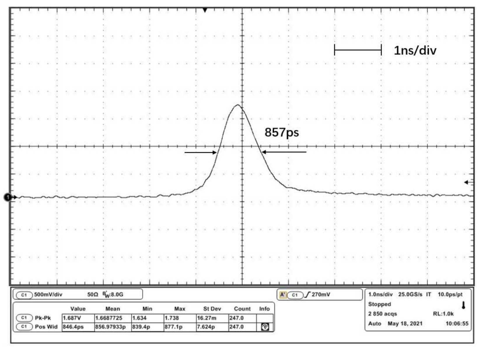
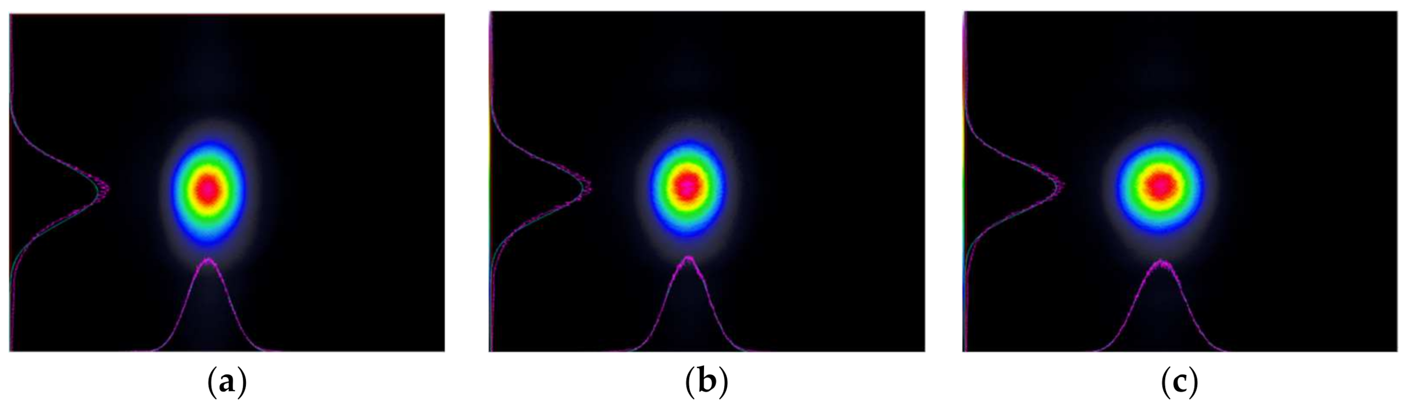
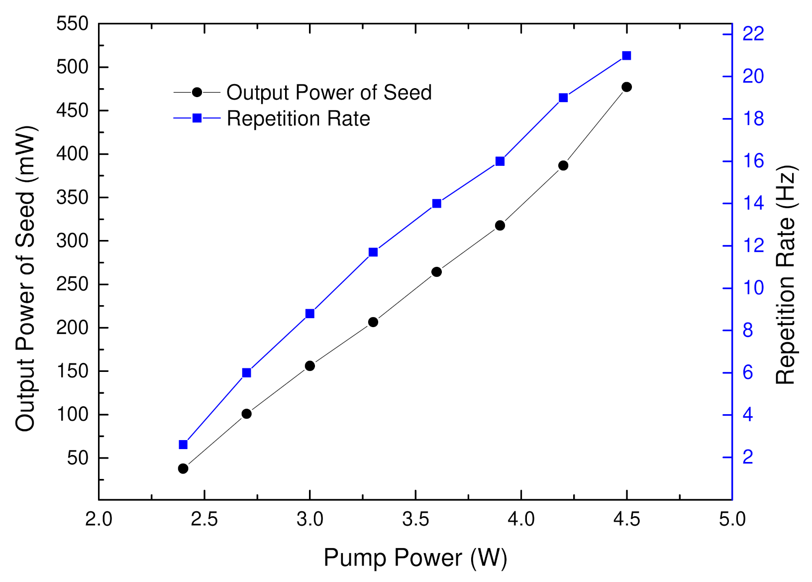
3.1. Seed Source Characteristics

In order to achieve high repetition, LD1 was run on the CW model. Due to the compact structure, a GRIN lens was selected for coupling the pump light. Both the repetition rate and output power increased when the pump power was increased, as Figure 2 shows. The temperature of LD1 during operation was controlled at 25 °C by the TEC for the ideal absorption efficiency of Nd: YAG. The seed’s output average power increased from 27.8 mW at 2.6 kHz to 477.2 mW at 21 kHz by adjusting the pump power from 1.4 W to 4.5 W. The average power and repetition rates were 317.8 mW and 16 kHz when the pump power was at 3.9 W. The single-pulse profile recorded by a Tektronix DPO70804C 8 GHz Digital Phosphor Oscilloscope and a DET025 A/M Photodetector of 2 GHz from THORLABS is shown in Figure 3. The full width at half-maximum (FWHM) of the laser pulse is 857 ps.

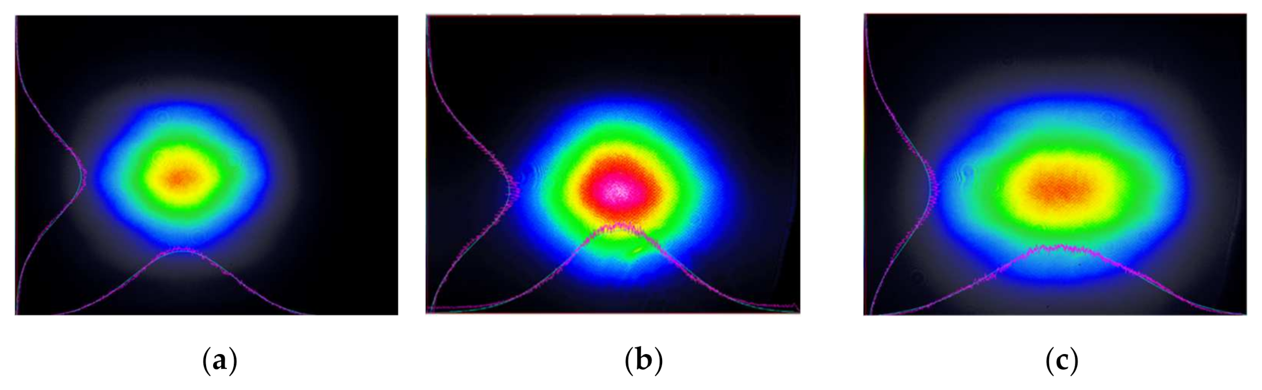
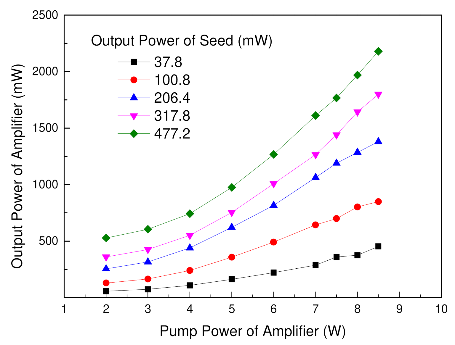
3.2. Two-Pass Amplification Characteristics

Figure 4 shows that the output power of the amplifier was a function of the seed’s output power and the amplifier’s pump power. The output power of the amplifier was 1.26 W, as the seed-injected power was 317.8 mW at 16 kHz and the pump power of the amplifier was at 7 W. The maximum output average power reached 2.3 W when the seed-injected power was 0.477 W at 21 kHz and the pump power of the amplifier was at 9 W.
The spatial profile of the fundamental beam was recorded with a LASERCAM HRⅡ camera from Coherent. Figure 5 shows the seed’s beam profiles at different pump powers, and the circularity levels we measured were 0.876, 0.829, and 0.779, corresponding to seed pump powers, respectively, of 2.4, 3.3, and 3.9 W.
The beam profiles after amplification under different seed pump powers are shown in Figure 6. As the pump power of the amplifier was at 7 W, the circularity levels we measured were 0.661, 0.747, and 0.927, corresponding to the seed pump powers of 2.4 W, 3.3 W, and 3.9 W, respectively. After amplification, the beam distortion of the seed was compensated well. The beam profile was more circularly symmetric. The circularity of the amplified beam with a pumped power of 7 W versus different seed pump powers are shown in Table 1. With the increase in pump power, the beam distortion of the seed was severe because of the increase in thermal loading. The distribution of the seed beam was divergent in the horizontal direction. For obtaining the ideal distribution of the fundamental amplifier, the cylindrical lens L2 was used for adjusting the pump distribution of the amplifier in the horizontal direction. We can conclude that the pump distribution of the amplifier was orthogonal to the distribution of the seed beam, since the pump power of the amplifier was constant. The beam distortion of the seed was compensated well owing to the restraint of the horizontal direction amplification and the enhanced vertical direction, as the pump power of the seed was 3.9 W. Therefore, as pertains to this experiment of amplification, the regulation of the pump distribution of the amplifier was effective in compensating the thermal-induced distortion of the seed beam. It would be helpful for the design of a high-beam-quality laser with a compact size.

3.3. SHG Characteristics

Due to the limitations in the volume and thermal control, we set the operating point of the amplifier at a pump power of 7 W, as the seed-injected power was 317.8 mW. The output average power of the fundamental laser was 1.26 W. Furthermore, we focused the fundamental beam on a 10 mm-long Type I LBO (θ = 90°, β = 11.4°) crystal for the SHG. The beam of 532 nm had an average power of 0.6 W with an RMS of 0.66% (recorded by the 4π power meter from Laser Point) at 16 kHz. The SHG efficiency of this laser was about 47.6% from 1064 nm to 532 nm. The pulse energy was 37.5 μJ, and the peak power was about 48.7 kW. The pulse width and repetition rate were recorded using a Tektronix DPO70804C 8 GHz Digital Phosphor Oscilloscope, and they were 769.6 ps and 16 kHz, respectively, as shown in Figure 7. The average value of the repetition rates was 16.22 kHz with a Std of 141.8 Hz, and the maximum value and minimum value were 16.57 kHz and 15.87 kHz, respectively.
Quality factor M 2 of the 532 nm at 16 kHz was recorded by M2-200 S-FW from Ophir-Spiricon with a 300 mm focal length lens. The values of M x 2 and M y 2 were 1.112 and 1.164, respectively, as shown in Figure 8.

4. Numerical Simulation for Sub-Nanoseconds

The passively Q-switched rate equations were first derived [17] by Szabo, A. and Stein, R.A., and Degnan, J.J. developed a method for optimizing the model of passively Q-switched rate equations [18]. Xiao, G. and Bass, M. presented a generalized model [19] of a passively Q-switched laser that can describe both ground and excited state absorption (ESA) at the laser wavelength of a saturable absorber. The rate equations are as follows:
d ϕ d t = ϕ t r 2 σ n l 2 σ gs n gs l s 2 σ es n es l s ln 1 R + L
d n d t = γ σ c ϕ n
d n gs d t = σ gs c ϕ n gs
d n es d t = σ es c ϕ n es
n gs + n es = n 0
T 0 = e n 0 σ gs l s
where ϕ is the density of the photon, t r is the round trip time, and σ is the radiation cross section of Nd3+: YAG. σ gs and σ es are the ground and excited state absorption cross sections, respectively. n is the inverted population density in Nd3+: YAG, while n 0 , n gs , and n es are the total doping particle density, and ground and excited state particle densities in Cr4+: YAG, respectively. l and l s are the lengths of Nd3+: YAG and Cr4+: YAG, respectively. T 0 and R refer to an initial transmittance of Cr4+: YAG and the reflectivity of the output coupler, respectively. γ refers to the level degeneracy factor, while L is the round trip loss in the cavity.
Based on the above equations, we processed a numerical simulation on output pulse widths with respect to the key parameters as an initial transmittance of Cr4+: YAG ( T 0 ), the reflectivity of output coupler ( R ), and the cavity length ( C L ). The results are given in Figure 9.
For obtaining sub-ns pulse widths, there are wider range options for T 0 and R as C L of 7 mm than C L of 9 mm, as shown in Figure 9. Some key parameters are shown in Table 2. As T 0 = 45%, R = 40%, and C L = 7 mm, the pulse width of the seed was expected to be about 850 ps. This resulted in a good agreement between the experiments and modeling.

5. Conclusions

In this study, we demonstrated a compact sub-nanosecond 532 nm laser with an average power of 0.6 W corresponding to the LD pumped whole power of 10.9 W, a repetition rate of 16 kHz, a pulse duration of 769 ps, and a pulse energy of 37.5 μJ, and the beam was characterized by M x 2 = 1.112 and M y 2 = 1.164. A MOPA system based on a passively Q-switched monolithic microchip laser was displayed in the experiment. However, the ideal average power of the microchip laser in the experiment was less than 317.8 mW, which was restricted by thermal loading. We proposed the power amplification and beam distortion compensation approaches in our experiments. Lidar with a high average power and corresponding pulse energies of the transmitter gives advantages in the detection distance and detection probability. The high beam quality contributes to increasing the efficiency of the transmitting optical system. Considering its high performance and compact characteristics, the reported sub-nanosecond laser can be widely used.

Author Contributions

Conceptualization, D.M., M.Z. and Z.F.; methodology, D.M.; simulation, T.W. experiment, M.Z. and T.W.; validation, Z.Q. and X.L.; supervision, Z.F.; writing—original draft preparation, D.M.; writing—review and editing, D.M. and X.L. project administration, D.M. All authors have read and agreed to the published version of the manuscript.

Funding

This research was funded by the National Key Research and Development Program of China (2020YFE0204600) and Key Research and Development Program of Tianjin (19YFZCGX00210).

Institutional Review Board Statement

Not applicable.

Informed Consent Statement

Not applicable.

Data Availability Statement

Not applicable.

Conflicts of Interest

The authors declare no conflict of interest.

References

  1. Zayhowski, J. Topical Papers on Microchip Lasers and Applications. Passively Q-Switched Microchip Lasers and Applications. Rev. Laser Eng. 1998, 26, 841–846. [Google Scholar] [CrossRef] [Green Version]
  2. Zayhowski, J.J.; Terry, J.; Clarkson, W.A. Compact solid state sources and their applications. In Solid State Laser Technologies and Femtosecond Phenomena; SPIE: Cergy-Pontoise, France, 2004; Volume 5620, pp. 155–169. [Google Scholar]
  3. Zayhowski, J.J.; Iii, C.D.; Cook, C.; Daneu, J.L. Mid- and High-Power Passively Q-Switched Microchip Lasers. In Advanced Solid State Lasers; The Optical Society of America: Washington, DC, USA, 2001; p. 1. [Google Scholar]
  4. Degnan, J.J. Photon-counting multikilohertz microlaser altimeters for airborne and spaceborne topographic measurements. J. Geodyn. 2002, 34, 503–549. [Google Scholar] [CrossRef] [Green Version]
  5. Degnan, J.J. Unified Approach to Photon-Counting Microlaser Rangers, Transponders, and Altimeters. Surv. Geophys. 2001, 22, 431–447. [Google Scholar] [CrossRef]
  6. Albota, M.A.; Heinrichs, R.M.; Kocher, D.G.; Fouche, D.G.; Player, B.E.; O’Brien, M.E.; Aull, B.F.; Zayhowski, J.J.; Mooney, J.; Willard, B.C.; et al. Three-dimensional imaging laser radar with a photon-counting avalanche photodiode array and microchip laser. Appl. Opt. 2002, 41, 7671–7678. [Google Scholar] [CrossRef] [PubMed] [Green Version]
  7. Degnan, J.J. Rapid, Globally Contiguous, High Resolution 3D Topographic Mapping of Planetary Moons Using a Scanning, Photon-Counting Lidar. In Proceedings of the International Workshop on Instrumentation for Planetary Missions, Greenbelt, MD, USA, 1 October 2012; p. 1086. [Google Scholar]
  8. Degnan, J.; Machan, R.; Leventhal, E.; Jodor, G.; Field, C. Photon-Counting, 3D imaging Lidars Operating at Megapixels per Second. In Proceedings of the Conference on Lasers and Electro-Optics/International Quantum Electronics Conference, Baltimore, MD, USA, 31 May 2009; p. CFJ6. [Google Scholar]
  9. Degnan, J.; Wells, D.; Machan, R.; Leventhal, E. Second generation airborne 3D imaging lidars based on photon counting-art. In Proceedings-Spie the International Society for Optical Engineering; International Society for Optical Engineering: Bellingham, WA, USA, 2007; p. 67710N. [Google Scholar]
  10. Isyanova, Y.; Wall, K.F.; Flint, J.H.; Moulton, P.F.; Degnan, J.J. High-Power, Short-Pulse, Compact SLR2000 Laser Transmitter. In Advanced Solid-State Photonics; Optical Society of America: Washington, DC, USA, 2004; p. MB14. [Google Scholar]
  11. Manni, J.G. Amplification of microchip oscillator emission using a diode-pumped wedged-slab amplifier. Opt. Commun. 2005, 252, 117–126. [Google Scholar] [CrossRef]
  12. Pavel, N.; Saikawa, J.; Kurimura, S.; Taira, T. High Average Power Diode End-Pumped Composite Nd:YAG Laser Passively Q-switched by Cr4+:YAG Saturable Absorber. Jpn. J. Appl. Phys. 2001, 40, 1253–1259. [Google Scholar] [CrossRef]
  13. Pavel, N.A.; Saikawa, J.; Shoji, I.; Dascalu, T.; Lupei, V.; Taira, T. All-solid-state diode and end-pumped Nd:YAG laser passively Q-switched by Cr4+:YAG saturable absorber. SPIE Proceedings 2004, 5581, 170–180. [Google Scholar] [CrossRef]
  14. Bhandari, R.; Taira, T. High Repetition Rate MW Peak Power at 532 nm Using Microchip Laser. In Libros profesionales de empresaon Lasers and Electro-Optics; The Optical Society of America: Washington, DC, USA, 2013; p. JW2A.26. [Google Scholar]
  15. Zheng, L.; Kausas, A.; Taira, T. >30 MW peak power from distributed face cooling tiny integrated laser. Opt. Express 2019, 27, 30217–30224. [Google Scholar] [CrossRef] [PubMed]
  16. Miao, J.; Wang, B.; Peng, J.; Tan, H.; Bian, H. Efficient diode-pumped passively Q-switched laser with Nd: YAG/Cr: YAG composite crystal. Opt. Laser Technol. 2008, 40, 137–141. [Google Scholar] [CrossRef]
  17. Szabo, A.; Stein, R.A. Theory of Laser Giant Pulsing by a Saturable Absorber. J. Appl. Phys. 1965, 36, 1562–1566. [Google Scholar] [CrossRef]
  18. Degnan, J. Optimization of passively Q-switched lasers. IEEE J. Quantum Electron. 1995, 31, 1890–1901. [Google Scholar] [CrossRef]
  19. Xiao, G.; Bass, M. A generalized model for passively Q-switched lasers including excited state absorption in the saturable absorber. IEEE J. Quantum Electron. 1997, 33, 41–44. [Google Scholar] [CrossRef]
Figure 1. Schematic of the sub-nanosecond laser.
Applsci 12 04428 g001
Figure 2. The average power and repetition rate of the seed versus pump power.
Applsci 12 04428 g002
Figure 3. The single-pulse profile and pulse width of the seed.
Applsci 12 04428 g003
Figure 4. The amplified power of the fundamental amplifier versus the power of the seed and the input pump power of the amplifier.
Applsci 12 04428 g004
Figure 5. The beam profiles of seeds at different pump powers. (a) Beam profile of the seed with a pump power of 2.4 W (the circularity was 0.876). (b) Beam profile of the seed with a pump power of 3.3 W (the circularity was 0.829). (c) Beam profile of the seed with a pump power of 3.9 W (the circularity was 0.776).
Applsci 12 04428 g005
Figure 6. The amplified beam profile of the fundamental laser with a pump power of 7 W at different pump powers of the seed. (a) Beam profile with circularity of 0.661, as the pump power of the seed was 2.4 W; (b) beam profile with circularity of 0.747, as the pump power of the seed was 3.3 W; (c) beam profile with circularity of 0.927, as the pump power of the seed was 3.9 W.
Applsci 12 04428 g006
Figure 7. The pulse width and repetition rate of 532 nm. (a) Single-pulse profile and pulse width. (b) Pulse train profile and the pulse repetition rate.
Applsci 12 04428 g007
Figure 8. Quality factor M 2 of the 532 nm beam.
Applsci 12 04428 g008
Figure 9. Pulse width change versus initial transmittance and reflectivity at different cavity lengths. (a) C L = 7 mm; (b) C L = 9 mm.
Applsci 12 04428 g009
Table 1. The circularity of the amplified beam with a pumped power of 7 W versus different pump powers of the seed.
The Pump Power of the Seed (W)The Output Power of the Seed (mW)Circularity of the Seed BeamCircularity of the Amplified Beam
2.437.80.8760.661
3.3206.408290.747
3.9317.80.7790.927
Table 2. Pulse width results for cavity lengths with 45% initial transmittance of Cr4+: YAG.
Cavity Length, CL (mm)Reflectivity of Output Coupler, R%Pulse Width (ns)
7350.909
400.851
450.809
9351.169
401.095
451.041
Publisher’s Note: MDPI stays neutral with regard to jurisdictional claims in published maps and institutional affiliations.

