Featured Application
Interfacial sensors or light modulators made of transparent dielectric materials alone.
Abstract
A simple scheme for single-channel coherent perfect absorption (CPA) of transparent materials is proposed and experimentally realized using total internal reflection by grazing incidence, with a single dielectric layer sandwiched by semi-infinite dielectric layers. In a 1.48-µm thick polyvinylpyrrolidone (PVP) film, dip-coated on a MgF2 substrate both transparent in the visible, reflectance dips due to nearly 90% absorption by single-channel CPA were observed in the wavelength range of 370–800 nm, with white light from a Xe lamp incident on the side face of the substrate and extracted from the other side through multiple reflections in the PVP layer. This is a simple and inexpensive CPA scheme, and it is expected to have various applications by changing the substrate/polymer material or dispersing molecules in the polymer film. This paper also provides a design guideline for grazing-incidence waveguide-mode sensors using transparent dielectric materials.
1. Introduction
The concept and experiment of coherent perfect absorption (CPA), in which 100% absorption is achieved by enhancing the absorption, due to the interference of (generally multiple) coherent light beams in a Fabry–Perot (FP) resonator, was reported in 2010 [1,2]. Since then, its realization in various systems has been reported and has made an impact [3]. The original proposal was to make two opposing coherent beams incident on a sample and to obtain complete absorption at the wavelengths that satisfy the CPA conditions. This also allows for effective nonlinear optical effects due to weak light, where a slight change in the intensity of one of the light beams changes the effective absorption coefficient. The method of making a single beam incident from one side of a sample and obtaining the counterpropagating beam from its reflection is now also regarded as single-channel CPA (SCCPA). Multichannel CPA provides better control of the CPA but requires a coherent laser light source and delicate alignment of the multiple laser beams, while SCCPA does not necessarily require a coherent light source and delicate alignment, but it needs a highly reflective structure on the sample.
Historically, SCCPA has been studied as a Salisbury Screen, asymmetric FP resonator, or critically coupled resonator [4,5,6]. The principle is as follows. The light reflected from the sample surface and the light emitted from the sample after being incident to and reflected multiply in the sample have the same amplitude and opposite phases, resulting in destructive interference. It has attracted attention as a mechanism for obtaining absorption close to 100% at subwavelength thickness [7] due to its potential application for highly efficient photodetectors and solar cells. For SCCPA, the other side of the sample should be highly reflective in order to obtain the counter propagating light coherent with the incident light. For this purpose, metallic mirrors, or distributed Bragg reflectors (or dielectric multiple layers), have been mostly utilized [4,5,6] while there have not been many studies of SCCPA with total internal reflection (TIR), which readily realizes 100% reflection just by preparing an appropriate dielectric interface. For example, SCCPA with TIR was observed for a nanometer-order thick, lossy metallic film on a dielectric prism [8]. The cases of subwavelength lossy layers ( are the real and imaginary parts of the refractive index) sandwiched by dielectric layers have been extensively studied [7,9]. Surprisingly, however, there has been no report on experimental realization of SCCPA using ordinary transparent dielectric layers with refractive indices of more than unity () and using the layer interface as a reflective surface by TIR.
On the other hand, although the relation to CPA has not been widely recognized so far, the detection of surface plasmon polariton (SPP) resonance, with a thin metal film deposited on the hypotenuse surface of a right-angle prism, has long been used as an interfacial sensor utilizing TIR. The principle that nearly 100% reflection dip is observed when the film thickness is adjusted to a certain level below 100 nm is nothing but critical coupling at which internal loss is equivalent to radiation coupling [10,11,12], i.e., SCCPA. In addition to the SPP sensor, a waveguide-mode (WM) sensor, which includes transparent dielectric layers on a prism, is also widely used [13,14,15,16]. In the SPP (WM) sensor, the angle of incidence [10,13,14] or wavelength [11,16] of light, which is resonant with SPP (WM), sensitively changes depending on the refractive index of the medium in contact with the metal film.
In this paper, we report the observation of reflection dips close to 90% for a thin film of transparent polymer on a transparent substrate in the visible light region. By taking advantage of the fact that CPA can achieve 100% absorption when there is a small amount of absorption even in almost transparent materials, the transmission spectra of a faint absorption of the film was measured with white lamp light illumination from side to side of the substrate (incident on the thin film from the substrate and then, totally reflected at the interface between the film and air). This work was motivated by a previous report [17] of the observation of a huge signal due to the Pockels effect of water [18] with a commercially available transparent electrode thin film on a glass substrate, which unintentionally satisfies conditions similar to those of CPA. Compared to the SCCPA scheme reported so far, this system can be easily prepared and is expected to have a wide range of applications, including use as a material for basic research because of its configuration being feasible without the need for expensive equipment or materials.
The thin-film structure and the optical geometry discussed in this paper are similar to that of the resonant mirror sensor [14,15], which is a kind of WM sensor. However, the thin-film structure proposed in this paper is not exactly the same as such sensors in that it requires grazing incidence to the thin film layer. To the best of our knowledge, there is surprisingly little literature that clearly describes the principles and conditions for the generation of sharp resonance in WM sensors, so this paper also provides a design guideline for a WM sensor of grazing incidence using transparent dielectric materials.
2. Principle
Let us explain the principle of SCCPA, considering the system as shown in Figure 1. Here, are the refractive indices of the substrate, the thin film (thickness ), and the surrounding medium, respectively. It is assumed that and are real while is complex, with being the extinction coefficient. When the angle of incidence to each layer is , the wavenumber of the incident light in vacuum is , and the phase change due to one-way propagation in the thin film is , the complex-amplitude reflection coefficient considering multiple reflections in the monolayer film is expressed by [19]
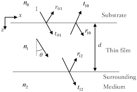
Figure 1.
Schematic of SCCPA with substrate 0, thin film 1, and surrounding medium 2. Collimated white light incident from the side of the substrate enters the thin film and is totally reflected at the interface between the thin film and the surrounding medium.
Therefore, the required condition of CPA is . When the incidence angle is greater than the critical angle of TIR () from layer to layer and , with being the phase shift by TIR for X (p or s) polarization. Then, and and are real, so and no reflection dip occurs. It is thus necessary for CPA to occur so that the thin film has even a small amount of absorption () [17]. In this case (), is complex and is not only complex (as usual for TIR) but also . For CPA (), therefore, the following two equations of real and imaginary parts (or magnitude and phase) should be simultaneously satisfied [7]:
and
with . If Equations (2) and (3) are satisfied with , then . This means perfect absorption because and the energy transmittance .
Since we are interested in the case where the thin film is almost transparent () but has a small absorption, it can be approximately assumed that is real and by TIR. Then, the approximate condition for CPA to be realized is
From , we know that must be close enough to 1. Therefore, note that Equations (10) and (11) in Ref [17] are approximate conditions for CPA and are not strictly correct.
To realize SCCPA in a transparent thin film using TIR, the following conditions must be satisfied, assuming that the thin film has very weak absorption () as a prerequisite:
- (a)
- The reflectance at the interface between the film and the substrate must be high [Equation (4)].
- (b)
- The film material must have a higher refractive index than the surrounding medium for TIR ().
- (c)
- From Snell’s law ofand Fresnel formulas for the reflection coefficients of s- and p-polarization:andwhere the condition (a) tells that or should be large (close to ). In addition, it is necessary that the light is incident from to [A: ] and TIR occurs from to [B: ]. If , these conditions are satisfied by bringing closer to . If , these conditions are satisfied by bringing closer to . However, multiple interferences at a nearly reflection angle within the thin film severely deteriorates visibility of interference when the beam size is finite. If , when [A] is satisfied, then there is a real angle to satisfy (TIR does not occur). Therefore, the necessary condition for SCCPA utilizing TIR is . Under the premise that a nearly transparent () dielectric material is used as the thin film, critical coupling, or SCCPA, requires an incidence angle from the substrate to the thin film close to , i.e., grazing incidence.
3. Materials and Methods
In the experiment, a polymer film and an inorganic substrate material with an appropriate combination of refractive indices were selected. The polymer film (), sandwiched between the substrate () and the air (), forms the FP resonator. Collimated white light was incident from the side of the substrate at an angle slightly different from normal incidence, and the light transmitted from the opposing side was detected. The light reflected from the polymer film surface when incident from the substrate and the light emitted from the film after being incident on and multiply reflected in the film cancel each other out by destructive interference, which is observed as a sharp reflection dip (CPA).
An MgF2 plate (refractive index 1.38, 20 20 5 mm3) purchased from Oyo Koken Kogyo Co., Ltd. (Tokyo, Japan) was employed as the substrate, and polyvinylpyrrolidone K25 (PVP, refractive index 1.53 at 510 nm, extinction coefficient 0.003) was purchased from FUJIFILM Wako Pure Chemicals Co. (Osaka, Japan). We chose PVP because it has a relatively high refractive index among polymers and can be deposited without water on MgF2, which is slightly soluble in water. A PVP film was dip coated on the MgF2 substrate. For dip coating, a linear guide (stroke length 100 mm, Heechoo, Shenzhen, China) was driven by a stepping motor (NEMA 17, 17HS4401, RATTMMOTOR, Changzhou, China) and stepping motor controller (LD09, Longruner, Shenzhen, China). Its speed was controlled by an Arduino Uno (Arduino). The MgF2 substrate was lifted from the chloroform solution containing 0.12 g/mL of PVP. The film thickness was adjusted to be uniform by varying the lifting speed from 4.08 to 4.04 mm/s.
Figure 2a shows the experimental setup for observing CPA, and Figure 2b shows how the light beam was incident on the sample for CPA. The white light from a Xe lamp, a laser-driven light source (LDLS EQ-99 X, Energetiq Technology, Wilmington, MA, USA), whose luminous spot size is specified as , was collimated with a Cassegrain mirror to form the collimated beam of about 1.3-mm diameter just before sample incidence. The light was s- or p-polarized with a polarizer and then, incident from the side of the substrate at an incidence angle of nearly ( to ), as defined in Figure 2b. The multiply reflected light in the sample was emitted from the opposite side of the sample. The light was sent through a fiber bundle to a polychromator (Acton SpectraPro-300i, Acton Research Co., Acton, MA, USA) with a diffraction grating of 150 lines/mm, 500 nm blaze, and the spectrum in the wavelength range of 370 to 800 nm was detected with a CCD.

Figure 2.
(a) Experimental setup. (b) Definition of the incidence angle in the experiment. The incidence angle for each layer in Figure 1 is determined so that , , and .
All the calculations were performed by Python using Equation (1), where the wavelength dependence of the refractive indices of MgF2 and PVP and that of the extinction coefficient of PVP were considered using the data in Refs. [20,21] as shown in Figure 3a,b. It is known that MgF2 is a birefringent crystal, although its anisotropy is small (for example, at 480 nm) [20], but we used the averaged refractive index for the calculation because the crystal axis is not specified in the substrate MgF2.
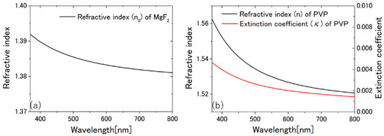
Figure 3.
The wavelength dependence of the refractive index () of MgF2 (a), and that of the refractive index () and the extinction coefficient () of PVP (b) [20,21].
4. Results and Discussion
Figure 4a–d show the sample photo and the evaluation procedure of the PVP film thickness, which was determined to be 1480 nm. The measured and calculated results of CPA, at an incidence angle () of are shown in Figure 5a,b, respectively. The measured reflectance is normalized to a maximum value of 1. From the full width at half maximum of the mercury emission line, the wavelength resolution of the experiment is 2.57 nm.
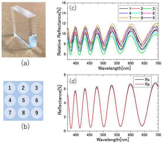
Figure 4.
(a) The photo of the PVP coated MgF2 substrate. At nine positions in (b), the reflectance relative to aluminum mirror was measured at an incidence angle of in air using a spectrophotometer (SolidSpec-3700 DUV, Shimadzu, Kyoto, Japan) as shown in (c). The position dependent variation of the interference fringe patterns was not significant. The film thickness was determined to be 1480 nm by comparing the experimental results (c) with the calculated result (d) using Equation (1).
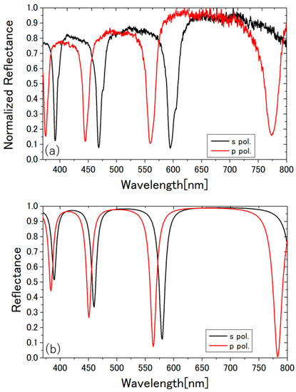
Figure 5.
(a) Reflection spectra (p- and s-polarized) of the transparent PVP film on the transparent MgF2 substrate at incidence in air, obtained from the side-to-side transmitted light spectra at incidence, divided by the baseline transmitted light spectra at incidence (= normal incidence from the side, thus transmitted through the substrate without being reflected by the PVP film), and normalized to 1 at the maximum value. The depth of the deepest reflectance dip is 92.6% at 594.7 nm for s-polarization and 89.4% at 559.4 nm for p-polarization. The raw reflection spectra, before normalization, and the baseline spectra are shown in Appendix B. (b) Calculated reflection spectra at the incidence angle from MgF2 to PVP, which corresponds to the incidence angle in air, with the thickness of the PVP layer assumed to be 1480 nm. The deepest reflectance dip has a 99.28% depth at 783 nm for p-polarization.
Figure 5a,b show that the experimental results were close to the calculated results, and that dips with a depth of nearly 90% were observed with the white lamp light source. The calculation shows that a dip with a 99.28% depth can be observed with p-polarization at 783 nm if the ideal measurement is realized. In the experiment, the depth of the dips decreased drastically when the angle of incidence was lower than 87.5 degrees (not shown). In Appendix A, the incidence angle () dependences of , the real and imaginary parts of , , , and at the wavelengths of the reflectance dips, are calculated to show that the deepest dip reaches 99.41% in depth.
The reasoning of the experimental CPA being a bit far from the 100% expected from the calculations is that the calculations were made assuming a plane wave (i.e., infinitely wide wavefront) and a perfectly flat and uniform thin film, whereas in the experiments, the beam was not perfectly collimated (because we collimated the light from an incoherent white light source with the finite spot size to a beam diameter of 1.3 mm) with an incidence angle distribution. Even without the angle distribution, oblique incidence with the finite beam size also deteriorated the visibility of interference. In addition, the thin film was neither perfectly flat nor uniform, and the spectrometer resolution was finite.
It is interesting to note that the spectral separation of the dips between s- and p-polarization is systematically larger in the experiment than in the calculation. A possible contribution of birefringence of the PVP film or the MgF2 substrate was checked by measuring the interference spectra of normal incidence, as in Figure 4c, with vertical and horizontal polarization, but little difference was found. Currently, therefore, the reason for this larger separation is unknown.
5. Conclusions and Prospect
We have theoretically explained and experimentally demonstrated that CPA is realized for an almost transparent sample in the visible light region, with a single dielectric layer sandwiched by semi-infinite dielectric layers. In the experiment, the transparent PVP film was deposited on the transparent MgF2 substrate, where the PVP film sandwiched between MgF2 and the air makes the FP resonator with TIR at the interface with air. Collimated white light from the lamp source was incident from the side of the substrate at an angle slightly deviating from normal incidence, and the minimum transmittance of over 90% (92.6%) dip was observed in the spectrum of the transmitted light emitted from the opposite side. The requirements (necessary conditions) for CPA in this configuration (a single layer slab thin film) are: (I) the transparent thin film must have a small amount of absorption, (II) , where are the refractive indices of the substrate, the thin film, and the surrounding medium, and (III) grazing incidence. The condition (II) is so constructed that light can enter the thin film when incident from the side of the substrate, and large reflectivity at the thin film-substrate interface as well as TIR at the thin film-surrounding medium interface are realized. The need for grazing incidence (III) comes from the approximate CPA condition of Equation (4): For transparent materials, is nearly zero, requiring nearly equals unity. Although the reflectance increases with the refractive index difference, as evident from Equations (6) and (7), grazing incidence allows to be as close to unity as possible, even when the refractive index difference is small. Therefore, there are countless other substrate-thin film combinations of transparent dielectric materials that can make CPA feasible, not only with the combination of solid-solid, but also with that of solid-liquid or liquid-liquid. For example, it has already been reported in Ref. [17] that it can be realized on a glass substrate (), with an ITO thin film () and water () as the surrounding medium.
The proposed configuration is one of the simplest and most inexpensive methods to realize CPA, as far as we know, and it is expected to have a wide range of applications due to its simplicity and extensibility. It can be immediately applied to optical notch filters. It can also be applied to interfacial sensors, including WM sensors [13,14,15,16], that detect refractive index changes at interfaces with high sensitivity, and optical modulators [17] that use the interfacial Pockels effect, both of which have already been realized. As a variation of WM sensors, a mechanical strain sensor, or bending sensor, is possible using polymer-polymer combination. Window glass that functions as a transparent solar cell [22] is now in practical use, and SCCPA can be used to increase its conversion efficiency when sunlight is obliquely incident (front and back surfaces should be non-parallel) by designing the CPA dip to be located just above the band gap. Faint absorption in the visible region of a thin film of a transparent material can be sensitively evaluated by solving the inverse problem, from the incidence angle dependence, of the SCCPA reflection spectra to obtain the complex refractive index (from the CPA dip, the approximate value for can be immediately obtained from Equation (4)). Since the visible absorption of water and organic solvents is very weak and difficult to measure by ordinary methods [23], there may be demand for this method, especially for ionic liquids for which it is difficult to prepare large quantities of samples [24]. Furthermore, it can be applied to experiments of nonlinear CPA by the Kerr nonlinearity [25] or by two-photon absorption [26] of polymers, liquids, or suitable dye molecules/nanoparticles dispersed in them using pulsed laser light, as well as to the photothermal imaging of transparent samples with nearly no absorption, which is a disadvantage of photothermal microscopy [27,28], where super-resolution images can be observed as long as the sample has absorption without the need for fluorescent labeling.
Author Contributions
Conceptualization, E.T.; methodology, E.T.; software, J.O.; formal analysis, J.O. and M.H.; investigation, J.O. and M.H.; resources, E.T., K.Y., K.S. and T.K.; data curation, J.O. and M.H.; writing—original draft preparation, E.T., J.O. and M.H.; writing—review and editing, E.T., K.S., K.Y. and T.K.; visualization, M.H.; supervision, E.T.; project administration, E.T.; funding acquisition, E.T. All authors have read and agreed to the published version of the manuscript.
Funding
This research received no external funding.
Institutional Review Board Statement
Not applicable.
Informed Consent Statement
Not applicable.
Data Availability Statement
The data that support the findings of this study are available from the corresponding author upon reasonable request.
Conflicts of Interest
The authors declare no conflict of interest.
Appendix A
The calculated incidence angle () dependences of . The real and imaginary parts of , , , and at the wavelengths of the reflectance dips are shown in Figure A1.
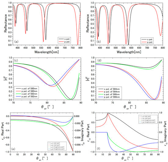
Figure A1.
The calculated incidence angle dependence of the reflection. The reflectance spectra of p- and s-polarized light at the incidence angle of (a) () and (b) (). The wavelength of the dip shifts with the incidence angle. (a) The deepest dip is 99. 28% at 783 nm for p-polarization. Between 550 and 600 nm, there are dips of an 87.77% depth at 580 nm for s-polarization and of 92.50% at 564 nm for p-polarization. (b) For s- and p-polarization, the deepest dip of a 99.41% depth at 582 nm and of 97.98% at 452 nm, respectively. The 580 and 564 nm dips at are shifted to 582 (99.41%) and 566 nm (97.86%) at . The incidence angle () dependence of the reflectance of s- and p-polarization (c) at 580 and 582 nm and (d) at 564 and 566 nm. The incidence angle () dependence of the real and imaginary parts of (e) and (f) at 564 nm.
Appendix B
For the reader’s reference, the raw reflection spectra before normalization and the baseline spectra for Figure 5a are shown in Figure A2.
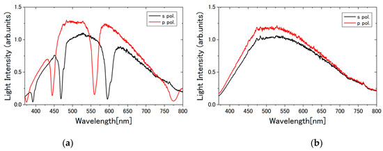
Figure A2.
Raw experimental spectra before normalization processing in Figure 5. (a) The reflected light intensity spectra (p- and s-polarized) of the transparent PVP film on the transparent MgF2 substrate at incidence in air. (b) The baseline transmitted light spectra (p- and s-polarized) at incidence ( normal incidence from the side, thus transmitted through the substrate without being reflected by the PVP film) used as the denominator for normalization.
References
- Chong, Y.D.; Ge, L.; Cao, H.; Stone, A.D. Coherent Perfect Absorbers: Time-Reversed Lasers. Phys. Rev. Lett. 2010, 105, 053901. [Google Scholar] [CrossRef] [PubMed]
- Wan, W.; Chong, Y.; Ge, L.; Noh, H.; Stone, A.D.; Cao, H. Time-Reversed Lasing and Interferometric Control of Absorption. Science 2011, 331, 889–892. [Google Scholar] [CrossRef] [PubMed]
- Baranov, D.G.; Krasnok, A.; Shegai, T.; Alù, A.; Chong, Y. Coherent Perfect Absorbers: Linear Control of Light with Light. Nat Rev. Mater. 2017, 2, 17064. [Google Scholar] [CrossRef]
- Fante, R.L.; McCormack, M.T. Reflection Properties of the Salisbury Screen. IEEE Trans. Antennas Propag. 1988, 36, 1443–1454. [Google Scholar] [CrossRef]
- Law, K.; Yan, R.H.; Merz, J.L.; Coldren, L.A. Normally-off High-contrast Asymmetric Fabry–Perot Reflection Modulator Using Wannier–Stark Localization in a Superlattice. Appl. Phys. Lett. 1990, 56, 1886–1888. [Google Scholar] [CrossRef]
- Tischler, J.R.; Bradley, M.S.; Bulović, V. Critically Coupled Resonators in Vertical Geometry Using a Planar Mirror and a 5 Nm Thick Absorbing Film. Opt. Lett. 2006, 31, 2045–2047. [Google Scholar] [CrossRef]
- Kats, M.A.; Capasso, F. Optical Absorbers Based on Strong Interference in Ultra-Thin Films. Laser Photonics Rev. 2016, 10, 735–749. [Google Scholar] [CrossRef]
- Driessen, E.F.C.; de Dood, M.J.A. The Perfect Absorber. Appl. Phys. Lett. 2009, 94, 171109. [Google Scholar] [CrossRef]
- Hägglund, C.; Apell, S.P.; Kasemo, B. Maximized Optical Absorption in Ultrathin Films and Its Application to Plasmon-Based Two-Dimensional Photovoltaics. Nano Lett. 2010, 10, 3135–3141. [Google Scholar] [CrossRef]
- Kretschmann, E. Die Bestimmung Optischer Konstanten von Metallen Durch Anregung von Oberflachenplasmaschwingungen. Z. Für Phys. A Hadron. Nucl. 1971, 241, 313–324. [Google Scholar] [CrossRef]
- Takagi, K.; Nair, S.V.; Watanabe, R.; Seto, K.; Kobayashi, T.; Tokunaga, E. Surface Plasmon Polariton Resonance of Gold, Silver, and Copper Studied in the Kretschmann Geometry: Dependence on Wavelength, Angle of Incidence, and Film Thickness. J. Phys. Soc. Jpn. 2017, 86, 124721. [Google Scholar] [CrossRef]
- Yoon, J.; Seol, K.H.; Song, S.H.; Magnusson, R. Critical Coupling in Dissipative Surface-Plasmon Resonators with Multiple Ports. Opt. Express 2010, 18, 25702–25711. [Google Scholar] [CrossRef] [PubMed]
- Knoll, W. Optical Characterization of Organic Thin Films and Interfaces with Evanescent Waves. MRS Bull. 1991, 16, 29–39. [Google Scholar] [CrossRef]
- Cush, R.; Cronin, J.M.; Stewart, W.J.; Maule, C.H.; Molloy, J.; Goddard, N.J. The Resonant Mirror: A Novel Optical Biosensor for Direct Sensing of Biomolecular Interactions Part I: Principle of Operation and Associated Instrumentation. Biosens. Bioelectron. 1993, 8, 347–354. [Google Scholar] [CrossRef]
- Daghestani, H.N.; Day, B.W. Theory and Applications of Surface Plasmon Resonance, Resonant Mirror, Resonant Waveguide Grating, and Dual Polarization Interferometry Biosensors. Sensors 2010, 10, 9630–9646. [Google Scholar] [CrossRef]
- Fujimaki, M.; Wang, X.; Kato, T.; Awazu, K.; Ohki, Y. Parallel-Incidence-Type Waveguide-Mode Sensor with Spectral-Readout Setup. Opt. Express 2015, 23, 10925–10937. [Google Scholar] [CrossRef]
- Hayama, D.; Seto, K.; Yamashita, K.; Yukita, S.; Kobayashi, T.; Kobayashi, T.; Kobayashi, T.; Tokunaga, E.; Tokunaga, E. Giant Pockels Effect in an Electrode-Water Interface for a “Liquid” Light Modulator. OSA Contin. 2019, 2, 3358–3373. [Google Scholar] [CrossRef]
- Nosaka, Y.; Hirabayashi, M.; Kobayashi, T.; Tokunaga, E. Gigantic Optical Pockels Effect in Water within the Electric Double Layer at the Electrode-Solution Interface. Phys. Rev. B 2008, 77, 241401. [Google Scholar] [CrossRef]
- Born, M.; Wolf, E. Principles of Optics: 60th Anniversary Edition, 7th ed.; Cambridge University Press: Cambridge, UK, 2019; ISBN 978-1-108-47743-7. [Google Scholar]
- Dodge, M.J. Refractive Properties of Magnesium Fluoride. Appl. Opt. 1984, 23, 1980–1985. [Google Scholar] [CrossRef]
- König, T.A.F.; Ledin, P.A.; Kerszulis, J.; Mahmoud, M.A.; El-Sayed, M.A.; Reynolds, J.R.; Tsukruk, V.V. Electrically Tunable Plasmonic Behavior of Nanocube–Polymer Nanomaterials Induced by a Redox-Active Electrochromic Polymer. ACS Nano 2014, 8, 6182–6192. [Google Scholar] [CrossRef]
- Lee, K.; Um, H.-D.; Choi, D.; Park, J.; Kim, N.; Kim, H.; Seo, K. The Development of Transparent Photovoltaics. Cell Rep. Phys. Sci. 2020, 1, 100143. [Google Scholar] [CrossRef]
- Litjens, R.A.J.; Quickenden, T.I.; Freeman, C.G. Visible and Near-Ultraviolet Absorption Spectrum of Liquid Water. Appl. Opt. 1999, 38, 1216–1223. [Google Scholar] [CrossRef] [PubMed]
- Paul, A.; Mandal, P.K.; Samanta, A. On the Optical Properties of the Imidazolium Ionic Liquids. J. Phys. Chem. B 2005, 109, 9148–9153. [Google Scholar] [CrossRef] [PubMed]
- Reddy, K.N.; Gupta, S.D. Light-Controlled Perfect Absorption of Light. Opt. Lett. 2013, 38, 5252–5255. [Google Scholar] [CrossRef] [PubMed][Green Version]
- Lyons, A.; Oren, D.; Roger, T.; Savinov, V.; Valente, J.; Vezzoli, S.; Zheludev, N.I.; Segev, M.; Faccio, D. Coherent Metamaterial Absorption of Two-Photon States with 40% Efficiency. Phys. Rev. A 2019, 99, 011801. [Google Scholar] [CrossRef]
- Miyazaki, J.; Kobayahsi, T. Photothermal Microscopy for High Sensitivity and High Resolution Absorption Contrast Imaging of Biological Tissues. Photonics 2017, 4, 32. [Google Scholar] [CrossRef]
- Adhikari, S.; Spaeth, P.; Kar, A.; Baaske, M.D.; Khatua, S.; Orrit, M. Photothermal Microscopy: Imaging the Optical Absorption of Single Nanoparticles and Single Molecules. ACS Nano 2020, 14, 16414–16445. [Google Scholar] [CrossRef]
Publisher’s Note: MDPI stays neutral with regard to jurisdictional claims in published maps and institutional affiliations. |
© 2022 by the authors. Licensee MDPI, Basel, Switzerland. This article is an open access article distributed under the terms and conditions of the Creative Commons Attribution (CC BY) license (https://creativecommons.org/licenses/by/4.0/).