1. Introduction
Next-generation passive optical networks (PON) have been under rapid development to fulfill the ever-increasing bandwidth and traffic requirements in the access and short-reach communications segment. The standardization of higher speed PON targeting 50 Gbps per wavelength (
λ) has been recently performed by ITU-T [
1,
2,
3,
4]. However, next-generation 5G and 6G systems will require even higher data rates, and PONs represent a suitable practical technology to support future optical access solutions [
5,
6,
7,
8]. Currently, research efforts are targeting data rates of 100 Gbps per
λ and beyond [
9,
10,
11,
12,
13,
14,
15,
16,
17] for the next step of PON evolution.
The latest PON standards (i.e., 25G-PON and 50G-PON) have chosen the direct detection (DD) scheme to meet cost requirements, and O-band operations for both upstream (US) and downstream (DS) directions to cope with chromatic dispersion [
1,
2,
3,
4]. However, the penalty due to chromatic dispersion is not negligible at high data rates, such as 200 Gbps, even in the O-band. Compared to the O-band, the C-band can provide a lower optical loss and optical nonlinearity. For higher speed PON upgrades, backward compatibility with legacy Gigabit PON (G-PON) (currently, one of the most commonly deployed PON standards) can be achieved in the C-band by reusing the 1480–1550 nm wavelength range of the downstream. Moreover, the O-band window might become filled, opening to the possibility of considering the C-band again in future PON standardization efforts. To achieve this, dispersion must be compensated. Coherent detection is well-known to allow compensation of CD, power-fading effect and other impairments through digital signal processing, thus enabling C-band operation. In [
18,
19,
20], the possibility of using coherent detection has been studied. However, due to the high cost and complexity, the use of coherent detection in the cost-effective PON environment is still under discussion [
9,
18]. In a recent work [
15], we proposed chromatic dispersion digital pre-compensation (CD-DPC) for 100 Gbps links using a dual-arm in-phase and quadrature Mach–Zehnder modulator (IQ-MZM) at the transmitter (TX) side while keeping DD at the receiver (RX). This approach only increases complexity at the optical line termination (OLT) side, which in the PON downstream scenario is shared among the end users.
Increasing the target data rate requires pushing the system into nonlinear operation [
16,
17,
21] to be able to increase the transmitter launch power and the optical modulation index to achieve the demanding power–budget requirements. In [
16], we analyzed simple nonlinear compensation techniques, i.e., square-rootlike (SQRT) and polynomial (POLY) techniques. We simulatively and experimentally confirmed about 2 dB gain in terms of maximum optical distribution network (ODN) loss for a 100 Gbps downstream transmission, thanks to SQRT and POLY.
Next generation PONs must be backward compatible with legacy PONs, and the ODN must remain the same. Typically, at least a 29 dB link power budget (budget class N1) and a 0 to (at least) 20 km fiber reach must be guaranteed [
1,
2,
3,
4,
22]. Regarding the trend of ITU-T PON standardization evolution, at least a 4-fold increment in DS capacity can be observed between 2 consecutive PON system generations [
2,
4]. For example, there is a 4-fold increment in DS capacity from a GPON (with DS 2.5 Gbps per
λ) to XG(S)-PON (with DS 10 Gbps per
λ), and a 5-fold increment from a XG(S)-PON to a higher speed PON (with DS 50 Gbps per
λ). Therefore, it is expected that the next generation beyond 50G-PON will target (at least) 200 Gbps per
λ in DS. To meet the 29 dB ODN loss and 20 km fiber reach at 100 Gbps is very challenging, as we showed in previous works [
14,
15,
16,
17]. For a 200 Gbps per
λ transmission, the situation becomes extremely critical. In this paper, we focus on 200 Gbps per
λ transmission in a C-band to guarantee 29 dB ODN loss over a 20 km fiber link, by combining the CD-DPC algorithm with two nonlinear distortion compensation techniques: the SQRT [
16] and the Volterra nonlinear equalizer (VNLE) [
17]. In [
17], for 100 Gbps per
λ transmission in a C-band, we experimentally showed a 1–2 dB gain in term of ODN loss by using VNLE when compared to the SQRT.
Until now, non-return-to-zero on-off-keying (NRZ-OOK) modulation format has been defined for all standardized PONs. It is expected that 50G class optoelectronics (O/E) will be commercially available by the time 200 Gbps products are developed. However, devices to support OOK and 4-level pulse amplitude modulation (PAM-4) operations at 100 Gbaud or beyond seems difficult to achieve in the midterm [
3,
23]. Thus, we consider 8-level PAM (PAM-8) as a candidate modulation format for 200 Gbps transmission to have a reduced baud rate (i.e., around 66.67 Gbaud for 200 Gbps bit rate). In [
13], a 200 Gbps PAM-4 communication with a 29 dB ODN loss was experimentally demonstrated by using directly modulated laser (DML), direct detection and Raman amplification over a 21 km fiber. However, very high transmitter and receiver bandwidth devices, i.e., a 65 GHz DML and 70 GHz P-type-intrinsic-N-type diodes (PIN), were used in the experiments. Moreover, the strong Raman pumping used in the experiments is not suited for a cost-effective short-reach PON. In this paper, we demonstrate over 29 dB of ODN loss using 50G O/E devices without Raman amplification. In a 50G PON, the maximum launched power into ODN is +7, +9, +11 and +11 dBm for budget class N1, N2, E1 and E2, respectively [
24]. For 50G PON with a higher budget class, for example Class C+ (32 dB) and beyond, a minimum launched power of +10 dBm might be required. In PONs, a launch power a few dB higher than the minimum one can be tolerated [
25]. Transmitted optical power (TOP) could be increased to achieve the required link power budget. An electro absorption modulated laser (EML) boosted by an external semiconductor optical amplifier (SOA) can be placed at the TX side to increase launch power in PONs for a wide wavelength range of 1200–1650 nm [
26]. For a 50G PON, EML + SOA was exploited DS to support high budget classes. In [
25], a 14 dBm launch power was emulated by using EML + SOA. In [
27], an integrated EML + SOA with a 13 dBm output power was experimentally demonstrated to achieve a 35 dB link budget. In our previous works for 100 Gbps transmission, we used a TOP of 11 dBm. In this paper, we increase it to 15 dBm (when the VNLE is applied) to achieve the 29 dB power–budget requirements for 200 Gbps transmission.
The paper is organized as follows: the details of the simulation setup and simulated parameters are described in
Section 2. In
Section 3, we analyze the proposed system performance through simulations with variable transceiver bandwidth and for different RX DSP options. The complexity of different RX DSP options is compared in terms of multiplication per sample (MPS). Lastly, we discuss the results and draw some conclusions in
Section 4.
2. Simulation Setup
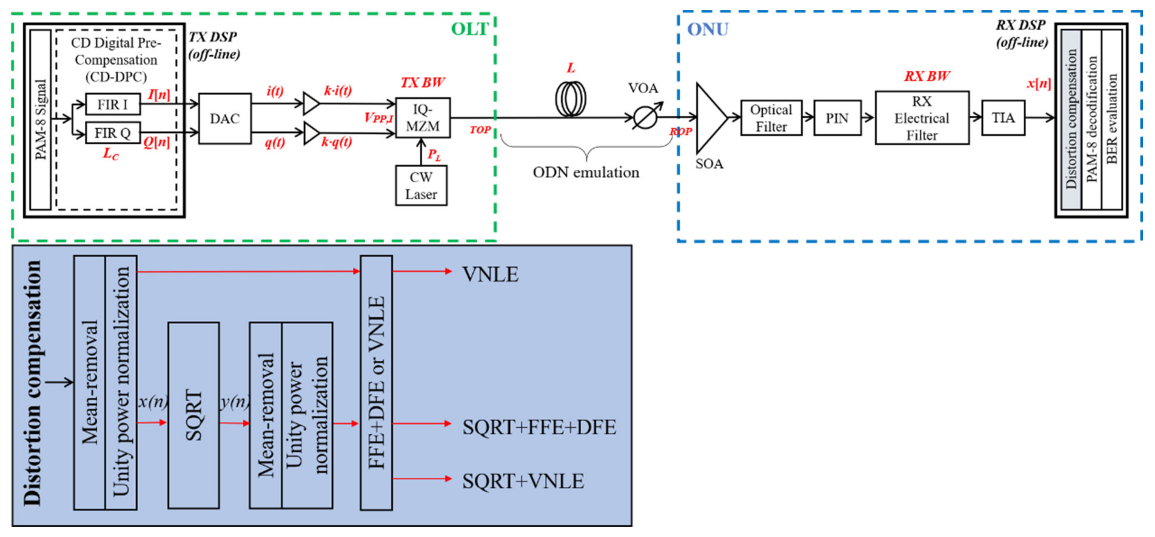
The simulation setup is schematically illustrated in
Figure 1. Single channel transmission is considered. At the TX side, a PRBS-15 pseudorandom binary sequence is generated at bit rate
Rb = 200 Gbps, and then coded to generate a PAM-8 sequence. As shown in
Figure 1, the CD-DPC algorithm is implemented based on a finite impulse response (FIR) complex filter, which is explained in detail in [
15]. The key idea behind this algorithm is the following: the fiber length
L is known in advance and the accumulated CD is
D∙L ps/nm (where
D is the dispersion coefficient). An electrical transmitted signal is sent to the FIR filter-based CD-DPC block, which works at
m samples per symbol (SpS) with
Nt taps. The CD-DPC block is placed at the TX side digital signal processing (DSP) and emulates the inverse of the CD accumulated along the link. A proper value of pre-compensated length
LC must be set in the CD-DPC block to design the taps of the FIR filter. As a result, an accumulated CD of
D∙LC ps/nm is assumed to be pre-compensated. There could be a mismatch
∆L between
L and
LC, (
∆L = LC − L), which the system should tolerate. In [
14,
15,
16,
17], we demonstrated a tolerance on
∆L of about ±2 km in a C-band for a 100 Gbps transmission through simulations and experiments. In this paper, the CD-DPC DD works at
m = 2 SpS and
Nt = 80. The I and Q arm of the dual-arm IQ-MZM are driven by two real-valued in-phase
I(
n) and quadrature
Q(
n) signals biased at quadrature and null point, respectively. The peak-to-peak amplitude
VPP of signal
I(
n) and
Q(
n), i.e.,
VPP,I and
VPP,Q respectively, are measured at the input of the IQ-MZM.
VPP,I and
VPP,Q must be optimized to obtain the best system performance by optimizing a scaling factor (the parameter
k in
Figure 1, which is the same for both
I(
n) and
Q(
n) signal). The simulator is explained in detail in [
15]. The bias voltage of the IQ-MZM
Vπ is 5 V.
The modulated optical signal in C-band at wavelength
λ = 1550 nm is propagated over a conventional ITU-T G.652 single mode fiber (SMF) with length
L = 20 km (typical for PON). The fiber attenuation, chromatic dispersion
D and non- linear coefficient
n2 are set to 0.22 dB/km, 17 ps/(nm∙km) and 26×10
−21 m
2/W, respectively. The effective area is 80 μm
2 [
28]. Kerr nonlinearities are introduced using the conventional nonlinear Schrödinger equation (NLSE) solved numerically by the split-step Fourier method. The received optical power (ROP) is measured after a variable optical attenuator (VOA) is used to emulate the ODN loss. Second order low-pass super Gaussian filters (SGF) are used to emulate the O/E bandwidth limitations with the same −3 dB bandwidth
f3dB both at TX and RX side. We analyze the impact of transceiver bandwidth limitations varying
f3dB from 30% to more than 100% of the baud rate, i.e., from 20 GHz to 70 GHz. At the RX side, an optical filter with a 75 GHz bandwidth is placed between the SOA and PIN. The receiver simulated parameters are SOA gain
G = 11 dB, SOA noise figure
NF = 7 dB, photodiode responsivity
R = 0.7 A/W, and transimpedance amplifier (TIA) input referred noise density
IRND = 12 pA/sqrt(Hz). A digital-to-analog converter (DAC) and an analog-to-digital converter (ADC) with a 6 bits resolution for quantization are used to emulate the arbitrary waveform generator (AWG) and real-time oscilloscope (RTO), respectively.
In the off-line DSP at the receiver, the digitized sequence is down sampled and off-line processed at 2 SpS, using one of the three DSP nonlinear distortion compensation methods shown at the bottom of
Figure 1. As detailed in [
16], the SQRT exploits a square-rootlike function, i.e.,
, and POLY consists of a polynomial function, i.e.,
, where
x(
n) and
y(
n) are the input and output signal of the SQRT (or POLY) block as shown in
Figure 1, and
α is a free parameter to be optimized. Since we also showed that a SQRT can provide a similar gain as POLY, but with lower complexity, in this paper we will consider the SQRT. We also analyze a technique based on the VNLE. To keep the complexity low, the VNLE is limited to third order, i.e., linear, quadratic, and cubic terms are considered [
29]. In our simulations, we set quadratic memory and cubic memory to be the same, and term them as nonlinear memory (NL memory). For example,
NL memory = 5 samples means
quadratic memory =
cubic memory = 5 samples. The three DSP nonlinear distortion compensation methods are: (i) the SQRT [
16,
30] in combination with a 120-taps feed forward equalizer (FFE) and a 5 taps decision feedback equalizer (DFE). We indicate it as “SQRT + FFE + DFE”. (ii) VNLE with 121 linear memory and a variable number of NL memory, ranging from 5 samples to 20 samples. We indicate it as “VNLE”. (iii) The SQRT in combination with the same VNLE as in option (ii). We indicate it as “SQRT + VNLE”. The SQRT + FFE + DFE method is equivalent to the VNLE method with
NL memory = 0. The transmitted optical power
TOP is set to 15 dBm for options with the VNLE (i.e., VNLE and SQRT + VNLE) and 11 dBm for the option without the VNLE (i.e., SQRT + FFE + DFE).
The typical metric used in a PON performance evaluation is the achievable ODN loss, calculated as the ratio between the TOP and the ROP. In this manuscript, we consider the required ROP (RROP) to obtain a BER target BERT = 10−2 (low-density parity check (LDPC) code forward error correction (FEC) scheme), and we will show system performance in terms of the maximum ODN loss that that guarantees operation equal to or below the BERT (Maximum ODN loss [dB] = TOP [dBm] − RROP [dBm]).
3. Simulation Results
In our simulation setup, shown in
Figure 1, we varied the transceiver bandwidth up to 70 GHz and the VNLE NL memory from 0 to 20 samples. We started by showing the impact of the normalized peak-to-peak amplitude of the in-phase signal
VPP,I/
Vπ by optimizing
VPP,I for options VNLE and SQRT + VNLE.
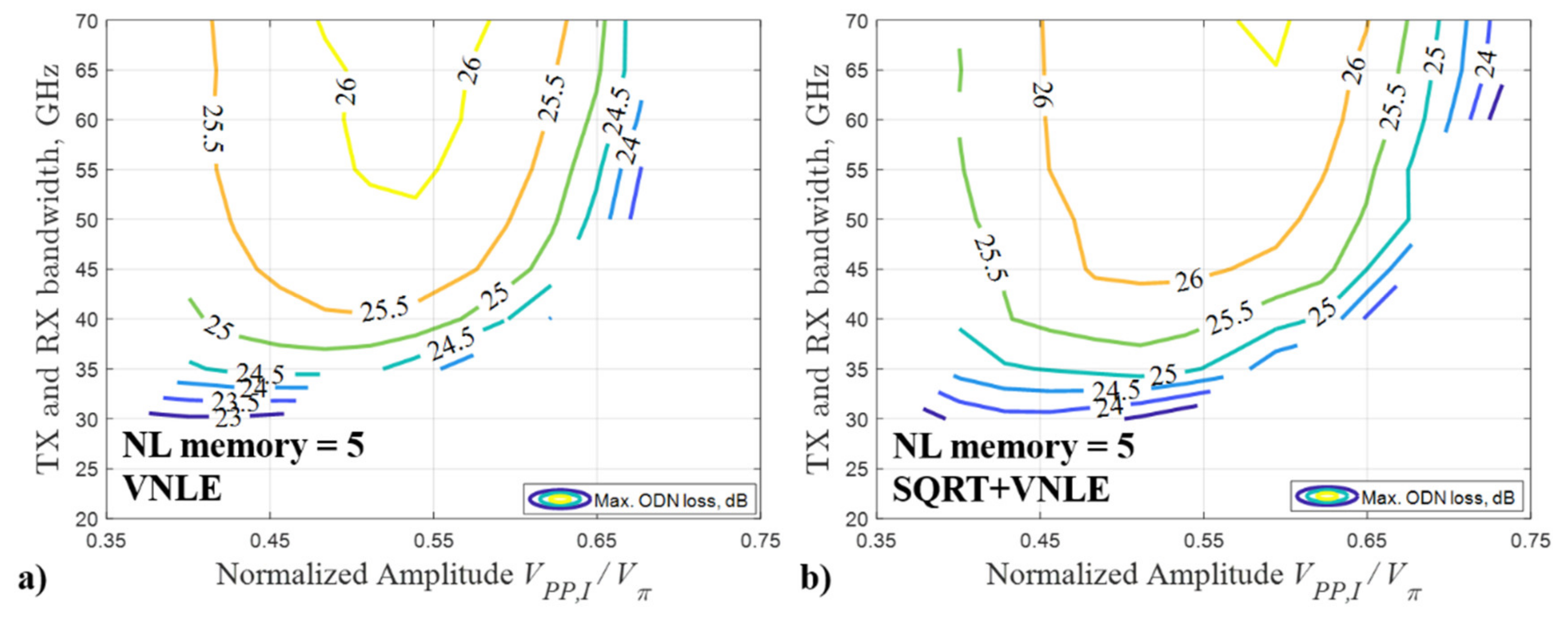
Figure 2,
Figure 3,
Figure 4 and
Figure 5 shows the system performance when
L = 20 km and
TOP = 15 dBm, in terms of the maximum ODN loss as a function of TX and RX bandwidth and of the normalized amplitude
VPP,I/
Vπ, for
NL memory = 5 samples, 10 samples, 15 samples and 20 samples, respectively. Note that the pre-compensated length
LC is optimized for each pair of the two parameters. The optimum
LC is slightly smaller than the fiber length
L, and the difference
ΔL between
L and
LC increases with TOP. For instance,
LC is around 18 km when
L = 20 km and
TOP = 15 dBm. This phenomenon is due to the interaction between the fiber Kerr effect and the chromatic dispersion, as explained in [
15,
31].
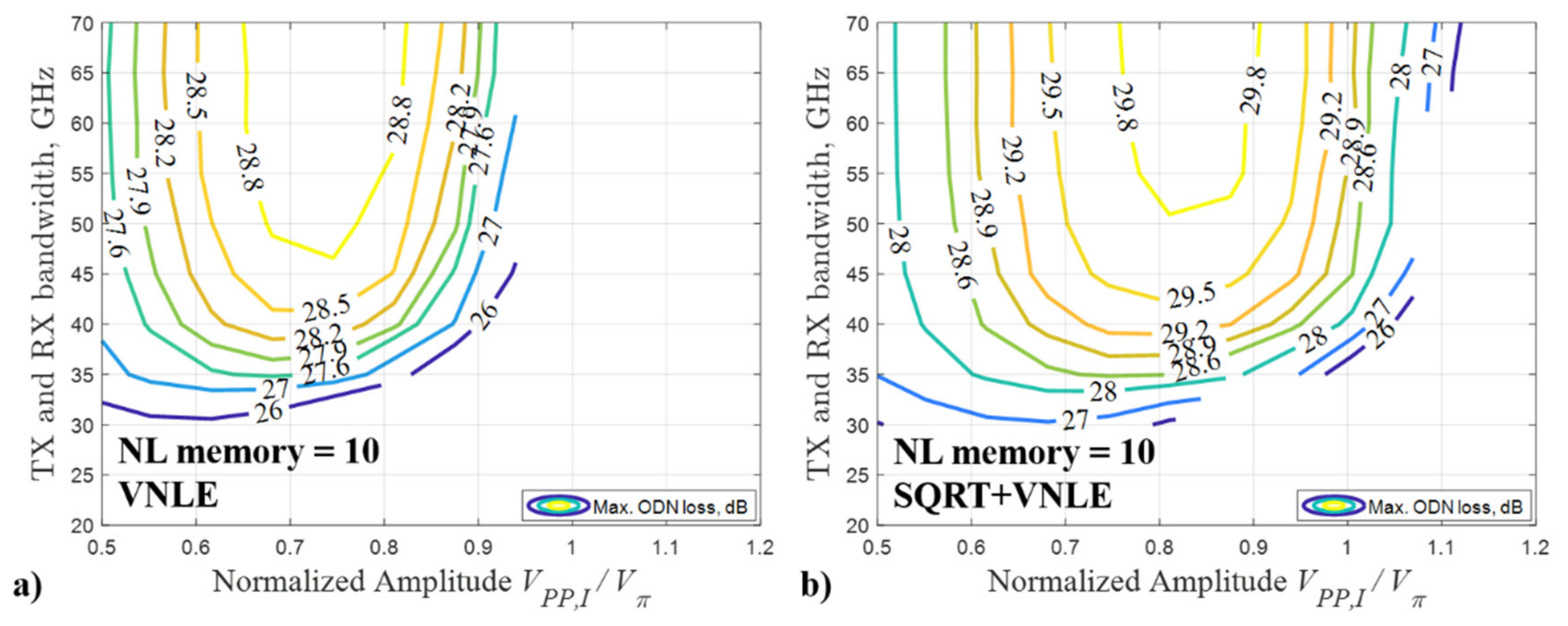
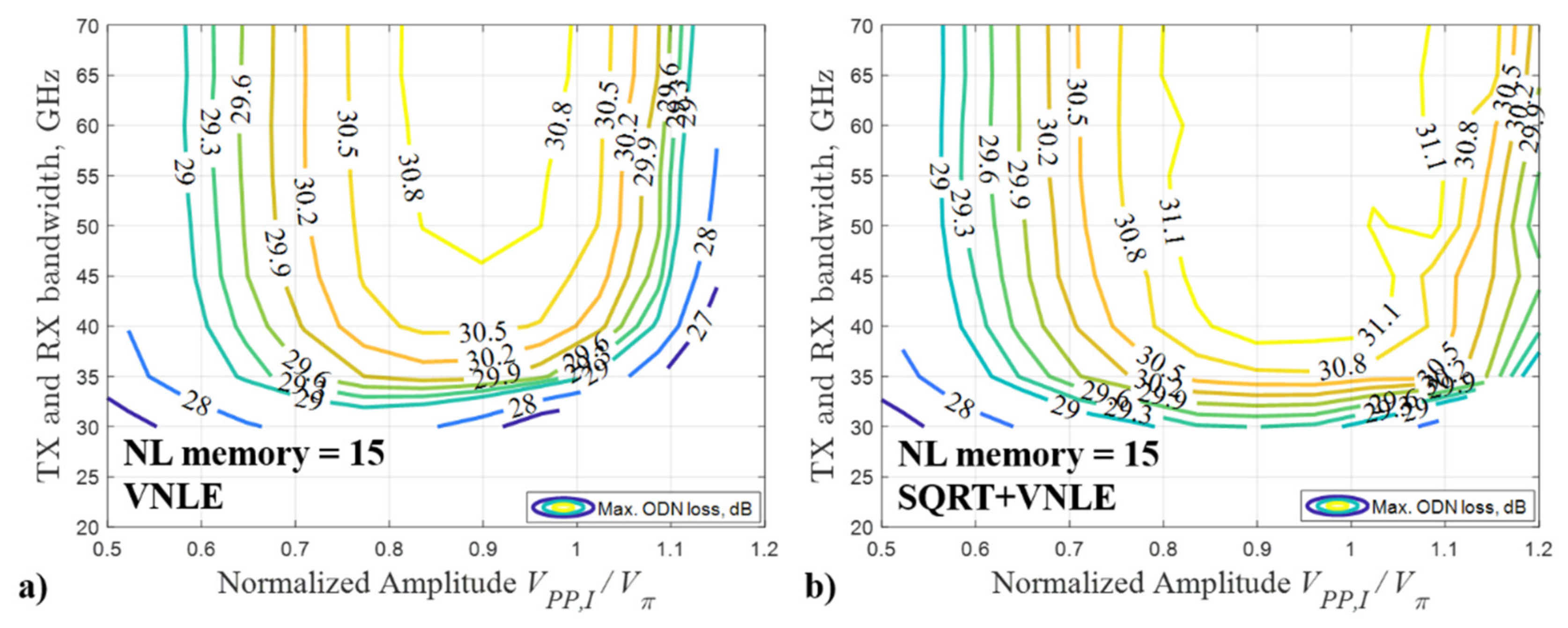
From
Figure 2,
Figure 3,
Figure 4 and
Figure 5, we can observe that the optimum normalized amplitude
VPP,I/
Vπ is in the range 0.55–0.60, 0.70–0.90, 0.90–1.00 and 1.00–1.10 for the VNLE NL memory equal to 5 samples, 10 samples, 15 samples and 20 samples, respectively. The optimum normalized amplitude
VPP,I/
Vπ increases as the NL memory increases. This can be explained considering the effect of the optical modulation index (OMI) on the nonlinearities generated in the modulation process. The OMI can be used to find the optimum operation point (at which the highest modulation levels can be obtained without introducing additional distortions) [
32]. Smaller
VPP,I/
Vπ results in lower nonlinearity of the modulation, but also into a lower modulation level. In contrast, larger
VPP,I/
Vπ can result in a higher modulation level but also in stronger nonlinear effects of the modulation. Therefore, it is very important to set the optimum driving signal amplitude by optimizing the normalized amplitude
VPP,I/
Vπ. Without TX and RX bandwidth limitations and at the optimum
VPP,I/
Vπ, when the VNLE is applied alone, the maximum ODN loss of about 26.1 dBm, 29.1 dBm, 31.0 dBm, and 31.7 dBm can be reached for
NL memory = 5 samples, 10 samples, 15 samples and 20 samples, respectively; when SQRT + VNLE is applied, the maximum ODN loss of about 26.6 dBm, 30.0 dBm, 31.7 dBm, and 32.0 dBm can be reached for
NL memory = 5 samples, 10 samples, 15 samples and 20 samples, respectively. The VNLE can provide up to 3 dB improvement for every five samples additional NL memory, while the SQRT can provide about 0.5–1.0 dB improvement compared to the VNLE only option. However, the complexity of the VNLE is much higher than that of the SQRT (the complexity will be discussed and analyzed in detail in the following section). It is a trade-off between the system performance and the complexity of RX DSP options.
In addition to the modulation nonlinear effect and the fiber Kerr nonlinear effect, the nonlinear effect in the electrical domain caused by chromatic dispersion after the modulus square operation of DD (DD is inherently nonlinear due to the square-law detection) can be mitigated by using the SQRT as shown in [
30]. By comparing
Figure 2,
Figure 3,
Figure 4 and
Figure 5, we can also notice that the optimum normalized amplitude
VPP,I/
Vπ of the option SQRT + VNLE is slightly larger than that of the VNLE method (with the same NL memory). Therefore, a higher OMI can be set using VNLE with high NL memory combined with the SQRT, which allows to compensate for stronger nonlinear distortion.
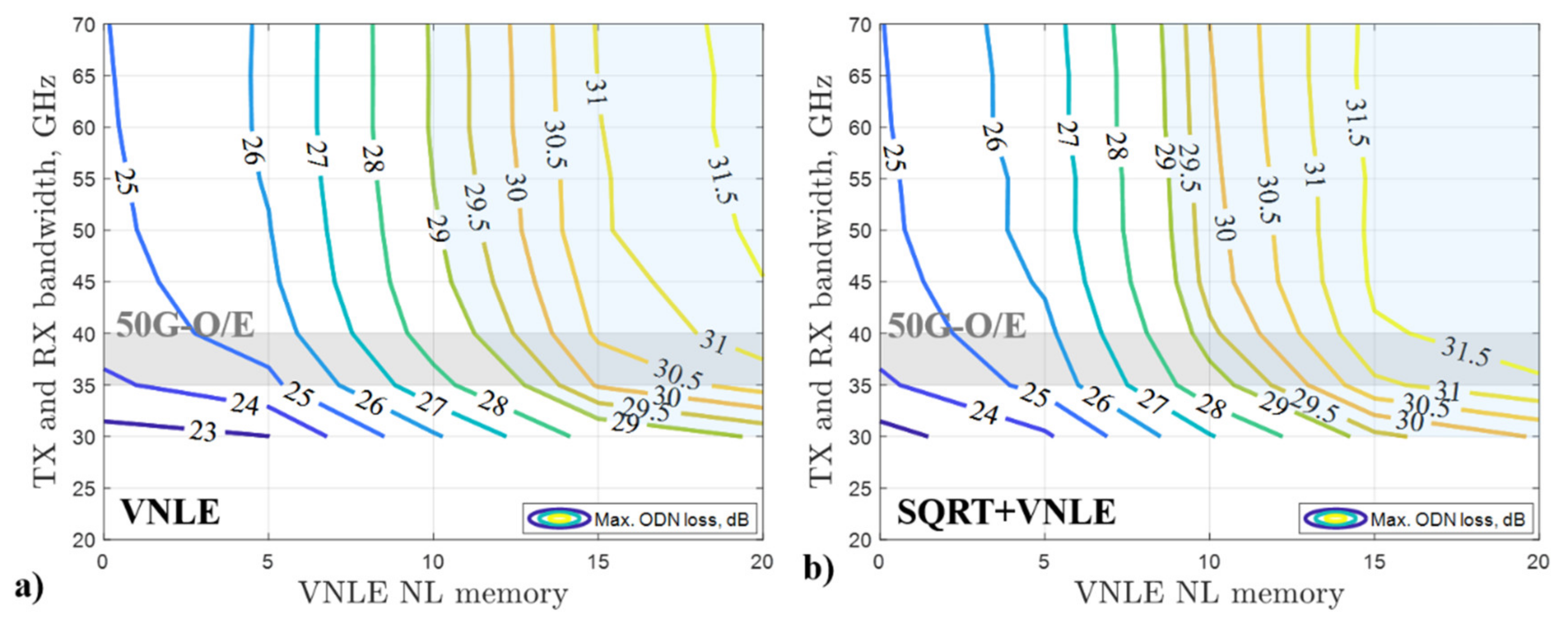
Figure 6 shows the maximum ODN loss as a function of TX and RX bandwidth and of the VNLE NL memory at the optimum normalized amplitude
VPP,I/
Vπ, for 20 km SMF. On the x-axis, the VNLE
NL memory equal to 0 corresponds to the SQRT + FFE + DFE technique used in the receiver DSP. This option, which does not include the VNLE, is used as the lowest complexity reference case. Note that, in all cases, the transmitted optical power, the normalized amplitude
VPP,I/
Vπ and the pre-compensated length
LC are optimized. The optimum
TOP is 11 dBm and 15 dBm for the SQRT + FFE + DFE and VNLE techniques, respectively. We limit our analysis to TOP = 15 dBm as higher transmitted power levels are unrealistic in PON applications. The optimum
LC is 19 km for SQRT + FFE + DFE (with 11 dBm TOP) and 18 km for the VNLE (with 15 dBm TOP). The optimum
LC decreases as TOP increases. This is related to the fact that a higher transmitted optical power results in a higher fiber nonlinear interference [
33], which partially counteracts CD due to interaction between the CD and the Kerr effect [
15,
31]. At the very demanding 200 Gbps rate, the system performance is very poor (maximum ODN loss <23 dB) when strong TX and RX bandwidth limitations are present (i.e., ≤25 GHz) even when using the most complex DSP approach (VNLE + SQRT with
NL memory = 20 samples). For SQRT + FFE + DFE (i.e.,
NL memory = 0), the largest maximum ODN loss is only about 25 dB even if using very high 70 GHz TX and RX bandwidth. Therefore, this simple DSP solution is not enough to meet the ODN loss requirement with PAM-8 200 Gbps transmission. By using the VNLE, both alone and in combination with the SQRT, a considerable gain can be obtained when we increase the NL memory. As shown in
Figure 2,
Figure 3,
Figure 4,
Figure 5 and
Figure 6, about 3 dB, 5 dB and 6 dB maximum ODN loss increase can be obtained when the NL memory is increased from 5 samples to 10 samples, 15 samples and 20 samples, respectively. The trend shows that the improvement would be very limited by further increasing the NL memory above 20 samples. This means that almost all the fiber nonlinear interference is compensated for by the VNLE. About a 3 dB gain in terms of maximum ODN loss can be obtained by relaxing the TX and RX bandwidth limitation from 30 GHz to 50 GHz, with the same NL memory. As shown in
Figure 6, for a fixed NL memory value, the improvement is more evident when increasing the TX and RX bandwidth from 30 to 40 GHz. When the TX and RX bandwidth are above 50 GHz, only very limited improvement can be obtained when TX and RX bandwidth are increased.
System performance cannot be usually enhanced by relaxing the bandwidth limitations. More powerful RX DSP options are needed. Comparing the VNLE and the SQRT + VNLE, we observe a non-negligible ODN loss gain of about 1 dB, at the cost of slightly increased complexity due to the SQRT. Moreover, in some cases the overall complexity can be reduced by introducing the SQRT. As shown in
Figure 6a), in the 35 GHz to 40 GHz TX and RX bandwidth range representing commercially available 50G-O/E [
23], the VNLE approach requires NL memory from 12 samples to 13 samples to achieve 29 dB maximum ODN loss, whereas a lower 9 samples to 11 samples NL memory is needed when combining the VNLE and the SQRT (see
Figure 6b)). This reduction in NL memory can provide a significant improvement in RX DSP complexity in terms of MPS, which will be discussed later. When
NL memory = 20 samples is applied, the 29 dB maximum ODN loss can be reached even with 30 GHz TX and RX bandwidth, at the cost of a very high DSP complexity (which will be discussed later).
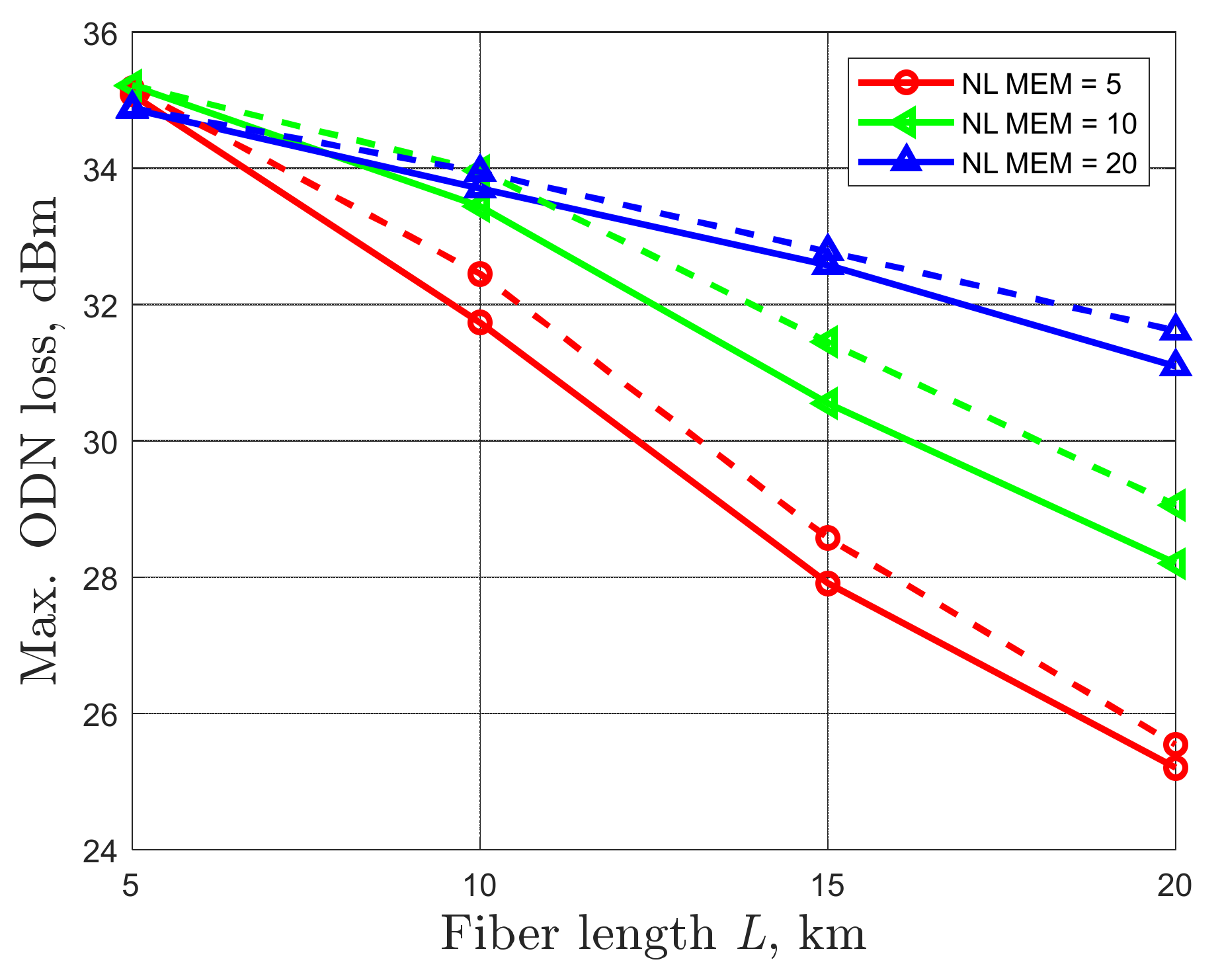
It is typical in PON architectures that each served ONU is located at a different distance from the OLT. In
Figure 7, we present the maximum ODN loss as a function of fiber link lengths
L ranging from 5 km to 20 km, which is the typical reach range in PONs. TX and RX bandwidth is set to 37.5 GHz, a typical value for 50G-O/E devices [
23]. In all cases, the normalized amplitude
VPP,I/
Vπ and the pre-compensated length
LC are optimized. For
L = 5 km, the optimum
LC is 4 km and 4.5 km for the VNLE and the SQRT + VNLE, respectively. The optimum
LC is 9 km, 14 km, and 18 km for
L equal to 10 km, 15 km, and 20 km, respectively. We select the VNLE
NL memory = 5 samples, 10 samples and 20 samples. The maximum ODN loss gain obtained by increasing the NL memory increases as the fiber length
L increases. At very short distance, for example
L = 5 km, the improvement is negligible due to the limited nonlinear distortions introduced by the fiber. To achieve 29 dB ODN loss, only
NL memory = 5 samples is required for
L ≤ 14 km, whereas
NL memory = 10 samples is required for
L in the 15–20 km range.
In PON solutions, the ONU is the most cost-sensitive element. Here we compare the complexity in terms of MPS of different RX DSP options, which are placed at the ONU side in the downstream transmission. The MPS of the SQRT, FFE, and DFE techniques can be calculated as described in [
17]. For the VNLE, the MPS can be evaluated by using Equation (5) in [
34]. In this paper, the order of VNLE is equal to 3, the linear memory is 121 samples, and the quadratic and cubic memory (NL memory) are equal to 5 samples, 10 samples, 15 samples or 20 samples. The complexity in terms of MPS of the different RX DSP used in the paper is summarized in
Table 1. The least complex method that allows us to achieve 29 dB maximum ODN loss with 50G-O/E devices (indicated with an asterisk in
Table 1) is the SQRT + VNLE with
NL memory = 10 samples, requiring 893 MPS. Small increments in NL memory (especially in cubic memory) can introduce a significant increase in complexity.
Although VNLE is an effective RX DSP option to compensate for linear and non-linear distortion, its complexity can be extremely high. The SQRT provides a marginal performance improvement but at the cost of a limited complexity enhancement by only 2 MPS. Thus, the SQRT can be used in combination with the VNLE to decrease the NL memory as well as maintain the desired system performance. For example, as shown in
Figure 6, to achieve ≥29 dB maximum ODN loss by using 50G O/E, when the VNLE is applied alone, NL memory of 12 samples and 13 samples is required for TX and RX bandwidth of 40 GHz and 35 GHz, respectively, which corresponds to MPS of 1369 and 1668. For the SQRT + VNLE technique, NL memory of 9 samples and 11 samples is needed for TX and RX bandwidth of 40 GHz and 35 GHz, respectively, which corresponds to MPS of 706 and 1111, respectively.


 ,
, 

