Article

Infrared Nanosecond Laser Texturing of Cu-Doped Bioresorbable Calcium Phosphate Glasses

by
Devanarayanan Meena Narayana Menon
,
Diego Pugliese
and
Davide Janner
*
Department of Applied Science and Technology (DISAT) and RU INSTM, Politecnico di Torino, Corso Duca degli Abruzzi 24, 10129 Torino, Italy
*
Author to whom correspondence should be addressed.
Appl. Sci. 2022, 12(7), 3516; https://doi.org/10.3390/app12073516
Submission received: 2 March 2022 / Revised: 25 March 2022 / Accepted: 28 March 2022 / Published: 30 March 2022

Abstract

:
The surface modification of bioactive glasses significantly impacts their performance for in-vivo biomedical applications. An affordable nanosecond pulsed laser surface-modification technique would provide great flexibility in applications such as cell scaffolding and fouling/anti-fouling engineered surfaces. This study reports on an infrared nanosecond laser modification technique we developed and applied to a Cu-doped bioresorbable calcium phosphate glass. With this technique, clean micro-protrusion features could be produced. By tuning the laser parameters such as the laser scan speed and average power, the width and height of the formed protrusions could be controlled. Finally, optimal laser parameters were defined to obtain complex surface textures without significant damage or thermal-stress-induced cracks. These results could provide effective aid for the affordable, fast, and selective surface texturing of metal-doped bioglasses, opening new possibilities in their application in the biological field.

1. Introduction

Glass-based materials are gaining a steadily growing importance in our daily lives. The combined optical and dielectric properties of glasses made it possible to envisage many advanced applications apart from their traditional uses. These include a variety of applications in diverse fields such as biophotonics, microfluidics, smart-materials, and non-linear optics, to name a few [1,2,3]. Glass materials exhibit, for instance, an inherent advantage for microfluidics owing to their rigidity and inertness to bio-chemicals, and their reduced absorption, unlike, e.g., soft Polydimethylsiloxane (PDMS) [4]. Another recent development of interest for glass materials is in bio-compatible glasses. Bioactive glasses have attracted great interest for their properties, particularly compared to polymers and metals [5]. Indeed, silica-based bioactive glasses are commonly used for dental and orthopedic applications. Despite various advantages associated with silica-based bioactive glasses, they are facing certain limiting factors for applications in the biomedical field. The high crystallization tendency of silicate bioactive glasses limits their use in the fabrication of porous scaffolds [6] and makes it difficult to draw them into fibers [7,8]. They were also found to have very slow biodegradability, which is highly undesirable in certain medical applications [9,10].
As an alternative, phosphate glasses have received increased interest lately due to their more reliable and controlled dissolution combined with superior thermal stability that enables them to be drawn into fibers or sintered into scaffolds [11,12,13,14]. This fact represents an added value in biological applications where the possibility of higher metal ions doping concentration, in comparison to silicate glasses, can provide phosphate glasses with special functional properties [15,16]. Copper has been officially recognized as a metallic anti-microbial agent by the Environmental Protection Agency in 2008 [17]. Cu-doped materials provide promising perspectives and there has been a strong research interest for their use in bioceramics, biocomposites, biometallic materials, and bioactive glasses [18]. By combining all the previous features, Cu-doped phosphate glasses can be regarded as an ideal platform to be used in biomedical applications, in particular for implantable devices or bioscaffolds that are able to reduce bacterial growth and promote specific cell cultures.
The wettability and surface texture of a bioactive glass play a significant role in protein adsorption or bacterial adhesion onto its surface [19]. In this regard, patternable surface texturing can enable scaffolding by allowing the selective growth of a specific strain of cells to grow, e.g., organoids, while reducing the potentially harmful growth of bacteria [20,21]. Various surface texturing techniques such as chemical etching, sandblasting, lithography, and electrochemical treatments are used to modify bioactive materials surfaces to achieve the desired functionality [22,23,24]. Another technique used to obtain such functional surfaces is based on sol–gel bioglasses. Indeed, they possess micro/nano-pores that increase the surface area, resulting in better interaction with the biological environment. However, sol–gel-based glasses show a much lower mechanical strength than the glasses synthesized through the melt-quenching technique, a fact that hinders their usability [25].
Compared to the above-mentioned techniques, laser micromachining represents a spatially selective and non-contact texturing method to process bulk glasses, introducing the desired surface functional features while preserving their bulk properties. Ultrafast lasers, i.e., femto- and pico-seconds, provide the unique advantage of allowing three-dimensional (3D) modification in glass structures with high precision. Material modification and interaction with these laser systems have raised an always-growing research interest in recent years [26,27]. Despite the precision attainable with these lasers, their typical initial investment cost and the slower throughput can prevent their adoption for mass production and limit their applicability. On the contrary, nanosecond (ns) infrared (IR) lasers are commonly employed in the industry for marking and cutting and could represent a much more affordable and scalable option if they can achieve efficient patterning of bioglasses.
We hereby present a study addressing the use of an IR ns-laser to microstructure a bioresorbable Cu-doped calcium phosphate glass using an affordable laser that could find interesting applications as, e.g., antibacterial transparent or scaffolding material. By studying different combinations of laser parameters, surface-modification features of different heights (2–12 μm) and widths (20–100 μm) could be obtained with potentially strong impacts for biological interactions [20]. The optimal condition of the laser processing of Cu-doped phosphate glass is also presented alongside a demonstration of surface patterning.

2. Materials and Methods

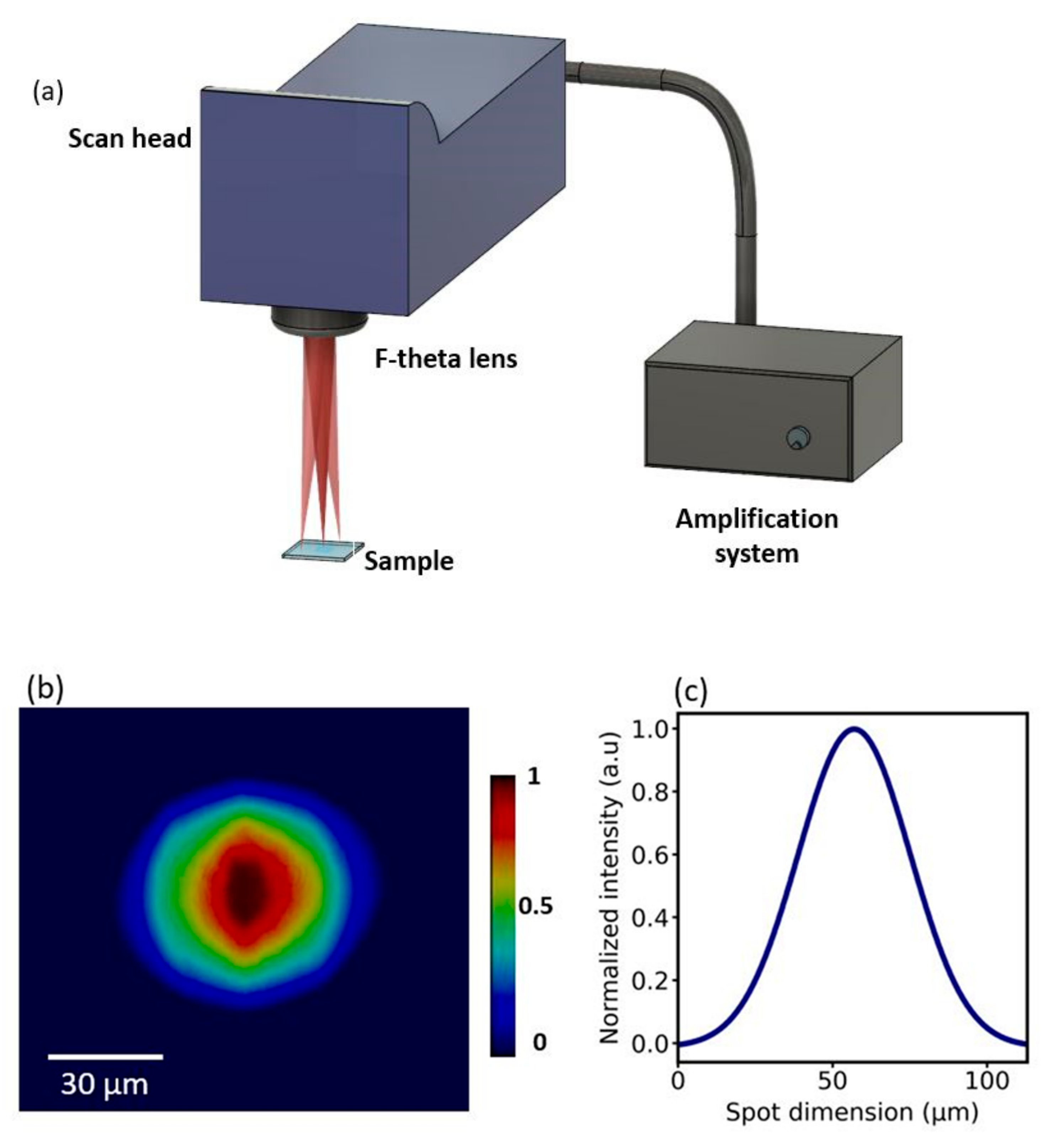
2.1. Glass Preparation and Laser Modification

The undoped and Cu-doped calcium phosphate glasses used in this work, with composition (in mol%) ((50 P2O5–25 CaO–8 MgO–11.5 Na2O–2.5 B2O3–3 SiO2)x–(CuO)y, with x = 1 when y = 0 and x = 0.99 when y = 1), were synthesized via a conventional melt-quenching technique using high-purity (99+%) biocompatible chemicals. The latter were weighed and mixed within a dry box to minimize the glass hydroxyl ions (OH) content. The batched chemicals were melted in a quartz crucible at a temperature of 1200 °C for 1 h under controlled atmosphere; the melt was cast into a preheated 8 mm diameter steel mold, then annealed at a temperature around the glass transition temperature, Tg = 443 °C, for 5 h to relieve internal stresses, and finally cooled down slowly to room temperature. The Cu-doped calcium phosphate glass was blue in color, and the absorption spectra of the glass samples were obtained using a dual-beam scanning spectrophotometer (UV-2600, Shimadzu, Columbia, MD, USA).
A ns IR (Nd:YVO4) Master Oscillator Power Amplifier (MOPA) fiber laser system (Datalogic Arex 20 MW, Bologna, Italy), with a central emission wavelength at 1064 nm, was used in this study. The laser is an industrial-grade system consisting of a galvo-scan system coupled with an F-theta lens at the output to facilitate the realization of complex designs on a two-dimensional plane. The effective focal length of the F-theta lens is 160 mm, providing a focal spot size of ~60 µm. A schematic diagram of the adopted laser system is reported in Figure 1a, while the Gaussian nature of the laser beam is shown in Figure 1b,c. For the current study, the pulse width delivered by the laser system was fixed at 4 ns at a pulse repetition rate of 20 kHz. The average laser power and scan speed were varied as the parameters of the present study. The modification characteristics of the generated surface features were studied by writing single scan lines for each selected parameter combination. The Gaussian beam profile was acquired using a camera (Pixelink CMOS USB 3.0, Ottawa, ON, Canada) and was further analyzed using the ImageJ software.

2.2. Surface Characterization

The optical microscopy images of surface modification were taken in phase contrast mode (OPTECH BM80, Munich, Germany). A scanning electron microscope (SEM) (JEOL-6000 Plus, Akishima, Japan) was used for the visualization and inspection of the surface morphology of the patterns.
The surface morphology was also analyzed using a stylus surface profilometer (Intra Touch, Taylor Hobson, Leicester, UK), and the data were processed using the ProfilmOnline analysis software.

3. Results and Discussion

As mentioned before, Cu-doped phosphate glasses provide bio-resorbability and antibacterial properties due to the inclusion of Cu2+ ions in the glass matrix [28]. Doping of metal species into the glass also causes a reduction in the absorption bandgap at both ultraviolet (UV) and IR wavelengths [29]. Characterizing the UV-to-IR absorption of the glass gives an understanding of the feasibility of laser processing of this phosphate glass at the laser wavelength of 1064 nm. Modifying the glass surface in a controlled manner needs an understanding of the laser parameters to be used for the surface modification, making it necessary for optimal processing conditions. Finally, we demonstrate the ability to fabricate patternable and crack-free modifications with the optimized laser parameters.

3.1. Absorption Characteristics of Calcium Phosphate Glass

Pure calcium phosphate glass does not appreciably absorb in the near-infrared (NIR) region. Doping the glass matrix with copper metal ions essentially reduces the absorption bandgap. This increased absorption in the IR could be attributed to the presence of Cu2+ ions in octahedral coordination facilitating intra-configuration (d-d) transitions [30,31]. The measured UV-Visible absorption spectra for the fabricated glasses reported in Figure 2 are coherent with the aforementioned effect of copper-ion doping into the glass matrix. Indeed, an apparent enhancement in optical absorption was observed at NIR wavelengths. It was also observed that the absorption enhancement at deep UV, i.e., ~300 nm, was much greater than that at NIR wavelengths. However, this study envisages the possibility of using an industrial-grade IR ns-laser (λ = 1064 nm) instead of more expensive UV ns or pico-second/femto-second (ps/fs) lasers.

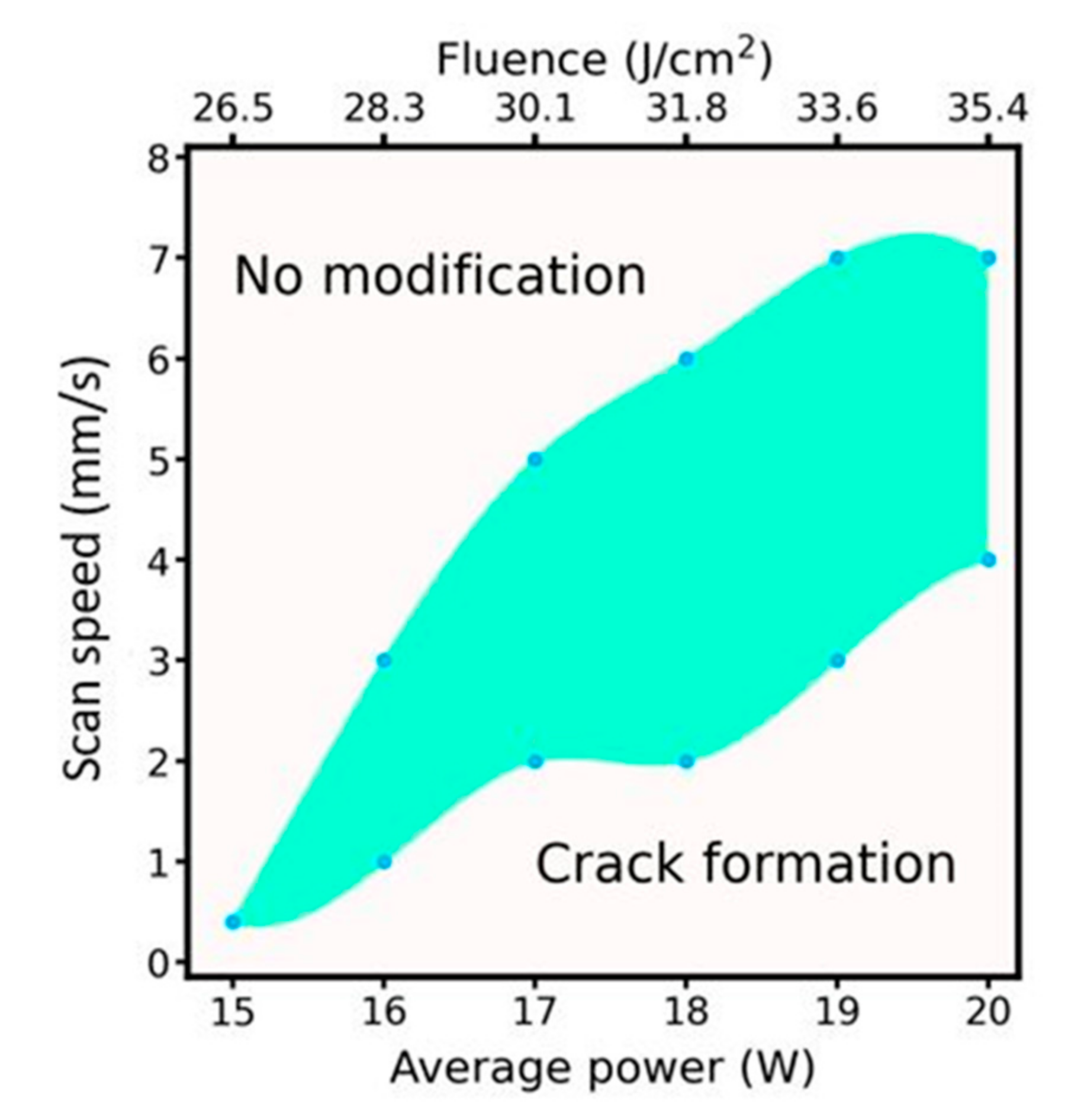
3.2. Glass Modification Threshold Test

At first, the minimum average laser energy required to cause a visible modification on the glass substrate was determined, with the rest of the laser parameters remaining fixed. The MOPA fiber laser offers the advantage of delivering variable pulse width in the range of 4–250 ns. The lowest pulse-width of 4 ns was chosen in this work to minimize thermal-based effects such as the Heat Affected Zone (HAZ) in the laser-modified region [32]. The pulse repetition rate and scan speed were fixed at 20 kHz and 3 mm/s, respectively. Interestingly, the commonly observed laser-induced material removal did not take place in the case of copper-doped phosphate glasses. Figure 3a,b shows two images taken at the same modification spot, but at different focal planes.
Upon focusing between the reference glass surface plane and the laser modification line, it is possible to see that the generated features along the laser scan line are in the form of protrusions above the reference glass surface plane as confirmed by the profilometer analysis presented later. The formation of micro-protrusion features, as depicted in Figure 3c, has an inherent relationship to the Gaussian energy distribution of the pulse and the temperature coefficient of surface tension dγ/dT of the glass. The Gaussian energy distribution would generate highest temperature at the center of the molten pool. Laser pulse interaction at the surface would cause rapid vaporization of the material, inducing a recoil pressure. The commonly observed micro-concave features after laser ablation are attributed to this recoil pressure. On the contrary, micro-protrusion features were obtained in the current study. This could be explained by a positive temperature coefficient of surface tension, which would mean the highest surface tension would be present at the center of the molten pool [33]. The temperature gradient of melt pool as a result of the Gaussian energy distribution of the pulse would thus cause a radially inward flow of the melt owing to inverse Marangoni flow [34,35,36]. To finally result in the observed protrusion features, the radial inward flow must overcome the recoil pressure effect caused by rapid vaporization. This inward flow drives the upward expansion of molten glass at the center of the melt forming the microfeatures on rapid cooling, as depicted in Figure 3c.
In general, for laser interaction with materials, controlled surface modifications can be obtained within a certain range of parameters. Especially for longer pulsewidths, i.e., nano, micro, millisecond, and continuous wave lasers, thermal effects play a major role due to the pulsewidth being longer than electron-phonon and phonon-phonon energy coupling time up to the order of few ps [37]. Such thermal effects are responsible for certain unwanted features such as HAZs and thermal-stress-induced cracks in glass materials. Therefore, it is important to properly define the laser parameters to minimize such unwanted effects as much as possible to obtain designable surface modifications.
Laser parameters of increasing average power and scan speed were studied to understand their effect on the modified surface features. An increasing average power at a constant pulse repetition rate would imply greater pulse energy. Since the ns pulsed modification is a thermal process, greater pulse energy would result in increased melt formation at the focus. Finally, this would imply a greater melt flow into the highest surface tension center of the Gaussian focal spot, resulting in increased height and width of the rapid cooled protrusion feature. The laser scan speed at a constant repetition rate controls the number of pulses at a single spot. Increased pulse numbers at a lower scan speed would also enhance the thermal effects at the focal spot, resulting in a similar effect to increased pulse energy. Figure 4 shows laser-modified single lines at varying average power, taken with a phase-contrast microscope. The laser power was varied in steps of 1 W from 10 up to 20 W.
These micro-protrusions started to be observable from an average power of 16 W. From Figure 4, it can be observed that the modification width increases with the power. However, the modification edge was very irregular for the lowest power modification, i.e., 16 W. This was not the case for higher powers that displayed cleaner edges and larger modification widths. Another important observation is that at the maximum power of 20 W, crack formation on the glass substrate was observed, and this is visible in the image. Such cracks are formed due to the thermal stress generated in very short times by excessively high heating and cooling of the glass substrate induced by the laser at the focal spot. The formed cracks were unevenly distributed and randomly formed during repeated processing with identical parameters.
Figure 5 presents the height and width of the protrusions for different average laser powers. It can be seen that they increase almost linearly with the laser power. In this study, the upper limit for average laser power was fixed at 20 W due to the inherent maximum permissible average power limit of the laser system.
Figure 6 shows the surface features of the modification as measured by the profilometer. An interesting aspect of the laser modification, in this case, was the occurrence of relatively clean edges, despite the expected HAZ generated by ns pulsed laser. This could be ascribed to the previously explained inward flow of glass beyond the softening point, contributing to the spatial rise of molten glass at the focal spot. Increasing the average power led to a much larger area of glass beyond the softening point. This implies more significant mass transport due to the inward flow towards the focal spot, resulting in a greater protrusion height above the planar glass surface.

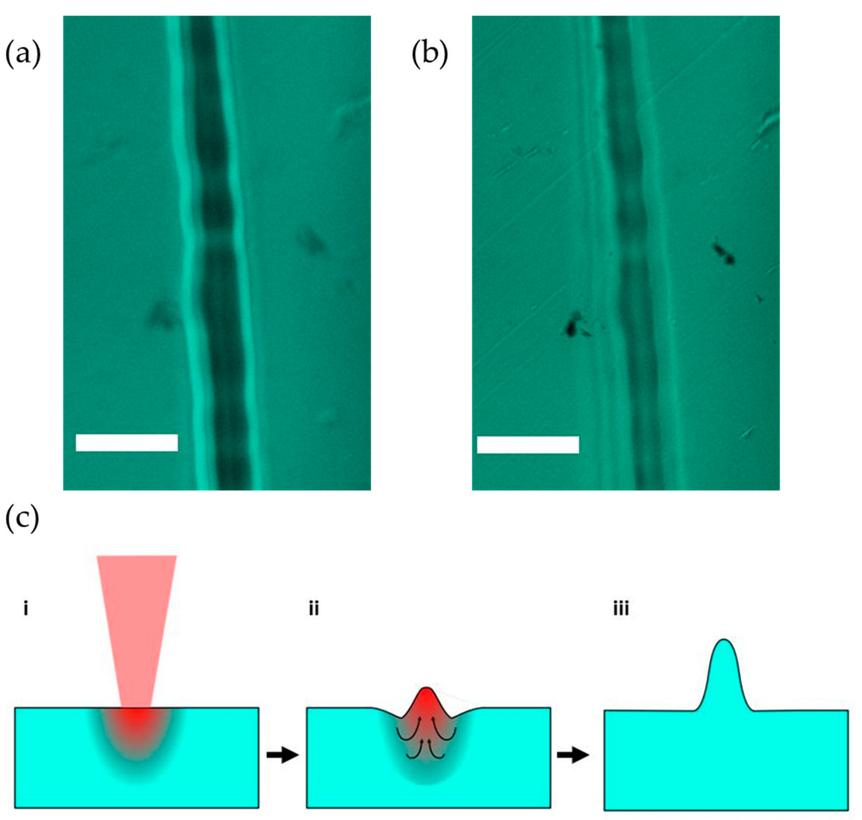
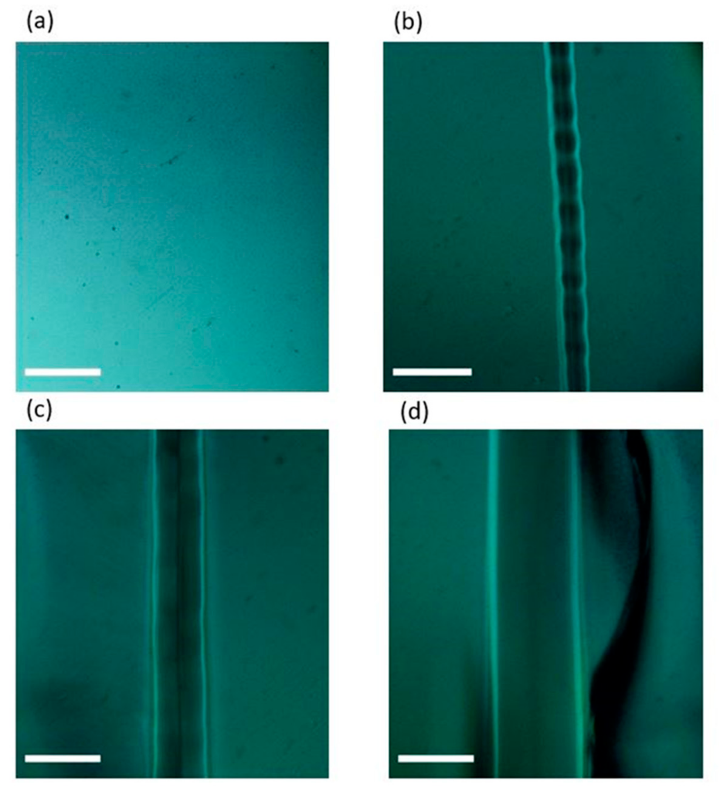
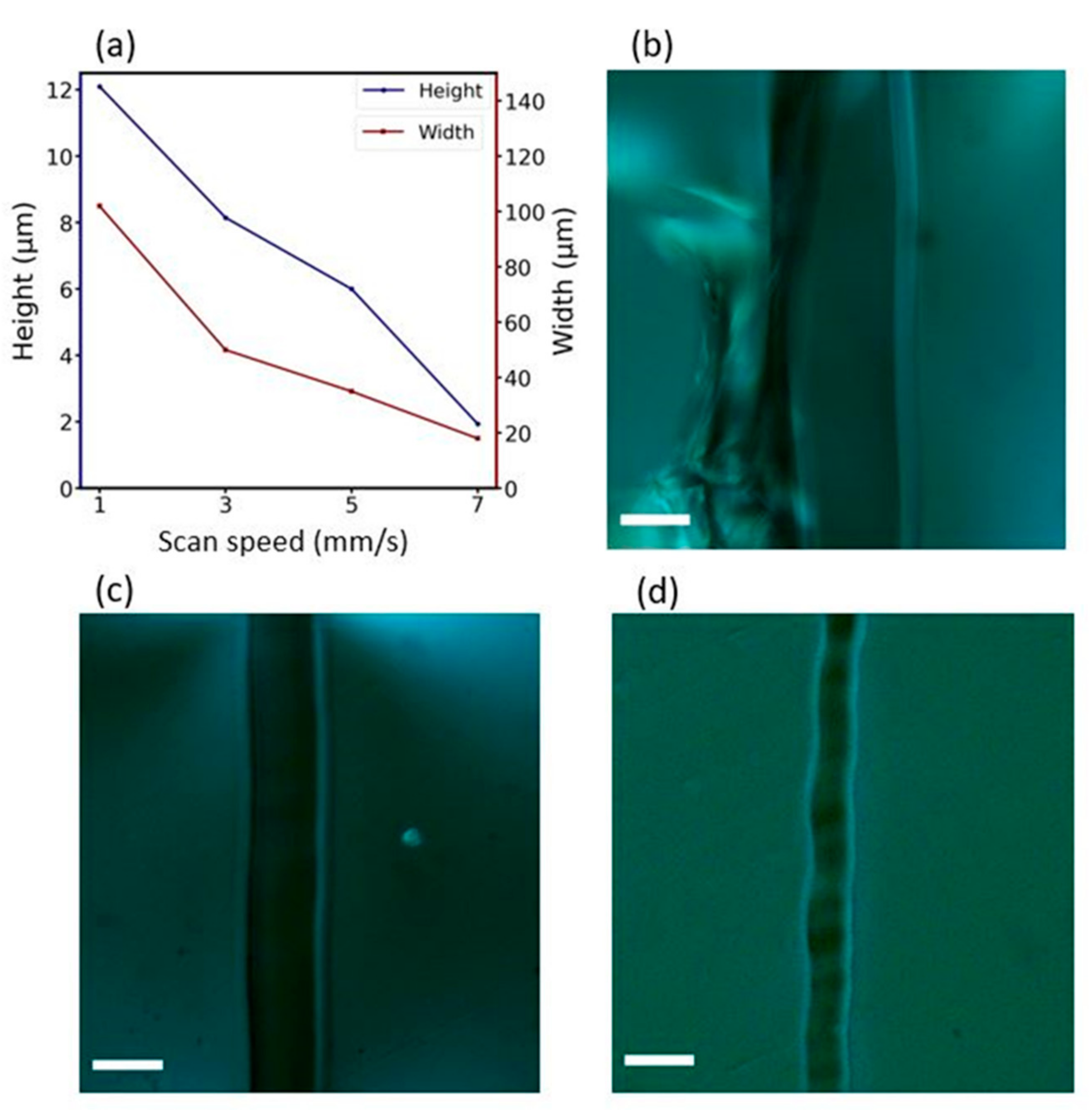
3.3. Scan Speed Effect on Morphology

After establishing the threshold power for the glass modification and its effect on the morphology, it is important to understand the influence of other parameters such as the scan speed. From this perspective, the power-variation study was also repeated for different scan speeds. At lower speeds, the number of pulses per spot increases for a fixed repetition rate. This impacts the local thermal dynamics and the resulting final modification. In the experiments, the scan speed was set at 1, 3, 5 and 7 mm/s. Figure 7a shows the plot of modification width and height changes for different scan speeds at a fixed average laser power of 19 W. The width and height of the microfeatures steadily decreased with increasing speed. This was expected, as with decreasing speed, more pulses are incident on the substrate at a single spot, generating increased thermal effects. The micrographs of laser modifications at varying scan speeds and at a fixed average power are reported in Figure 7b–d. Crack formation was evident at a speed of 1 mm/s due to greater energy deposition resulting in increased thermal stress. Modifications at the higher scan speed of 5 mm/s, on the other hand, occurred without crack formation but exhibited a wavy outline. As observable from Figure 7, for laser modifications at an average power of 19 W, a scan speed of 3 mm/s was found to be optimal for fabricating neat features.

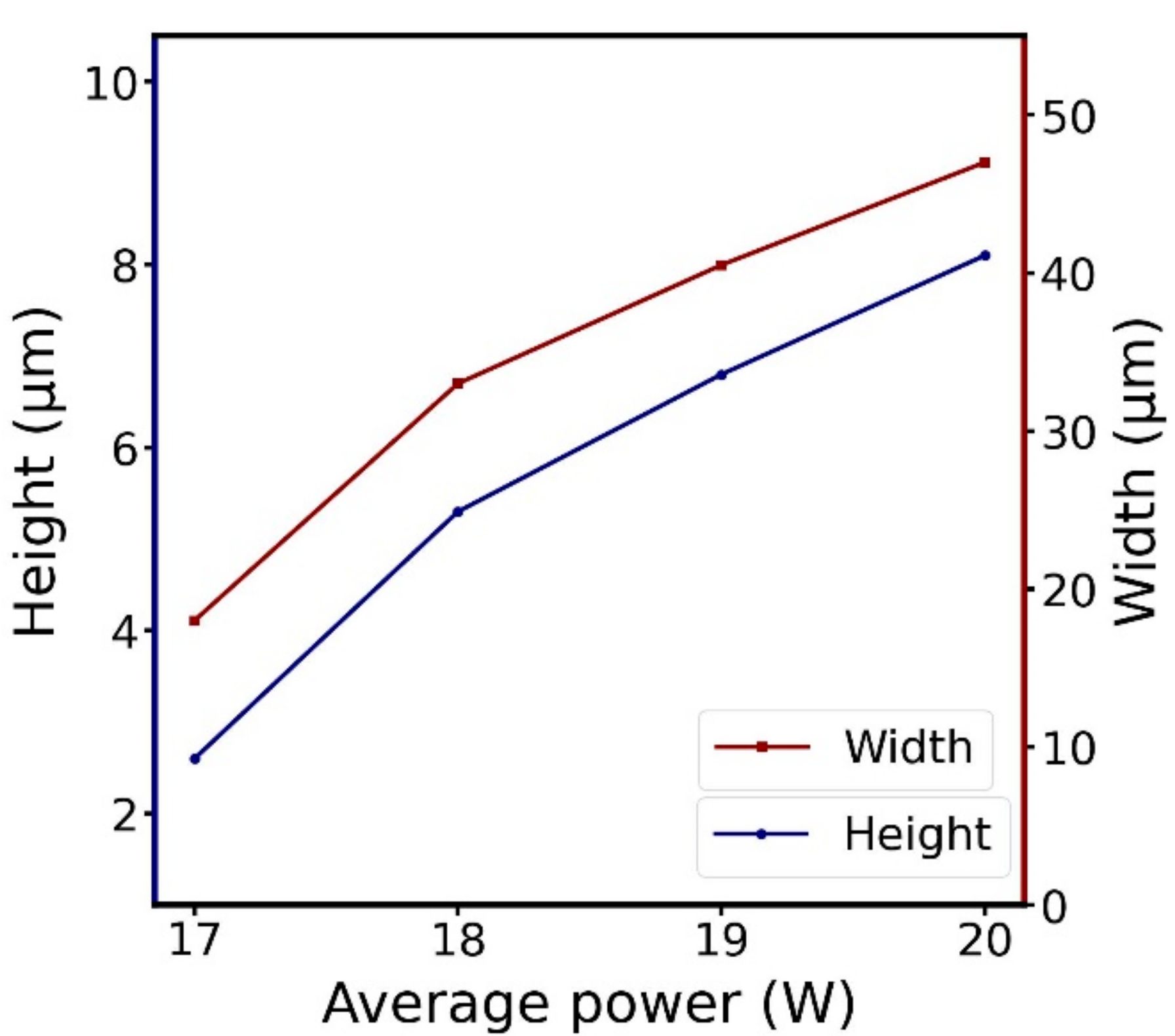
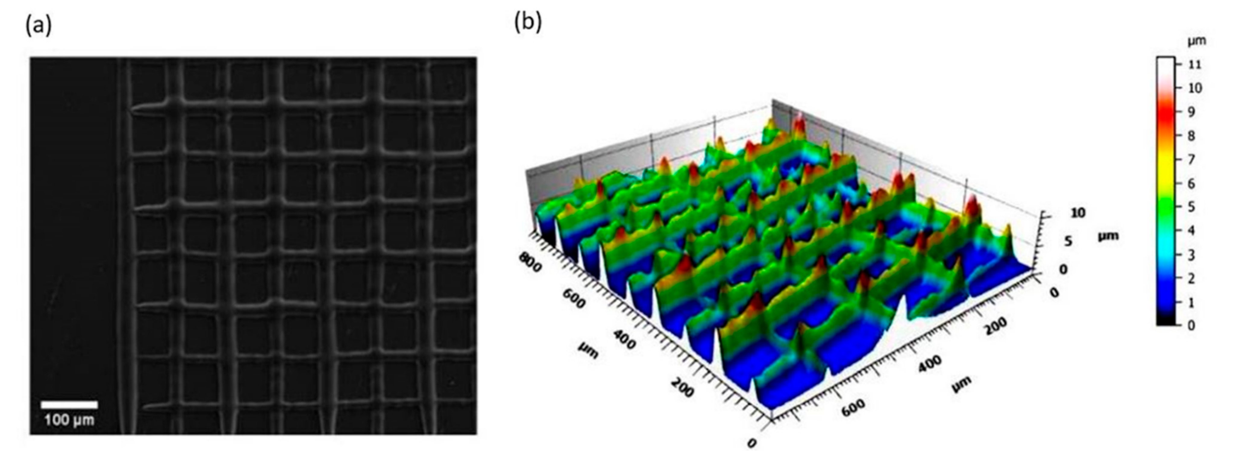
3.4. Optimal Parameters for Surface Processing

After characterizing the surface modification for laser parameters of average power and scan speed, it was necessary to define an optimal processing regime for a combination of the studied laser parameters. This provided a more complete characterization and also a reference for fabricating clean surface processing, devoid of cracks or other undesired surface features. For studies related to laser processing, a general parameter of importance is the laser fluence (F), defined according to Equation (1) as the energy delivered by pulse per unit area:
F = E p u l s e F A ,
E p u l s e = P a v g P R R ,
where E p u l s e is the pulse energy, F A the focal area, P a v g the average laser power, and P R R the pulse repetition rate. Here, the fluence is given in J/cm2, where J represents Joules.
Figure 8 displays the plot of the selected optimal process parameters, introducing laser fluence as a parameter.
The relation depicted in Figure 8 between the laser power and the laser scan speed for surface processing is coherent with thermal-based effects resulting in the surface texturing of the Cu-doped calcium phosphate glass. Having an idea of the optimal processing parameter window paves the way towards more advanced patterning to obtain more complex and functional surface textures without thermally induced cracks. As a test to demonstrate the patterning capabilities of the laser texturing on the glass, we defined a grid pattern at a power of 17 W and a scan speed of 2 mm/s. Figure 9 shows the SEM and profilometer analyses of an optimal surface modification. Such a grid texture with an average height of 7 μm can be employed as a surface for scaffolding cells. Even more geometrically complex structures can be generated and transferred with the laser controller, thus providing a powerful tool to easily explore the effect of different geometrical textures of this bioglass on the growth of cells and other biomedical applications.

4. Conclusions

This study investigated the laser–matter interaction between an IR ns-laser and a Cu-doped bioresorbable calcium phosphate glass fabricated by a conventional melt-quenching technique. Unlike the usually observed laser-ablated material removal, a protruding surface morphology was obtained, and the possible formation mechanism was discussed. Processing characteristics such as surface morphology, crack formation, and modification features were investigated for varying laser parameters such as average power and scan speed. Based on the results, the optimal processing window was defined, and a demonstration of grid texturing was realized, opening the path to obtaining more complex surface patterns. This paves the way for a flexible bioresorbable glass surface texturing technique for biomedical applications using an industrial-grade IR laser.

Author Contributions

Conceptualization, D.M.N.M. and D.J.; validation, D.M.N.M. and D.P.; investigation, D.M.N.M. and D.P.; writing—original draft preparation, D.M.N.M.; writing—review and editing, D.M.N.M., D.P. and D.J.; visualization, D.M.N.M.; supervision, D.J.; project administration, D.J. All authors have read and agreed to the published version of the manuscript.

Funding

This research received no external funding.

Data Availability Statement

Data available on request due to restrictions of privacy.

Acknowledgments

The authors acknowledge the support from Politecnico di Torino through the Interdepartmental Center PhotoNext. The authors also acknowledge the technical support from Datalogic.

Conflicts of Interest

The authors declare no conflict of interest. The funders had no role in the design of the study; in the collection, analyses, or interpretation of data; in the writing of the manuscript, or in the decision to publish the results.

References

  1. Tang, T.; Yuan, Y.; Yalikun, Y.; Hosokawa, Y.; Li, M.; Tanaka, Y. Glass based micro total analysis systems: Materials, fabrication methods, and applications. Sens. Actuators B 2021, 339, 129859. [Google Scholar] [CrossRef]
  2. Ferraris, S.; Yamaguchi, S.; Barbani, N.; Cristallini, C.; Gautier di Confiengo, G.; Barberi, J.; Cazzola, M.; Miola, M.; Vernè, E.; Spriano, S. The mechanical and chemical stability of the interfaces in bioactive materials: The substrate-bioactive surface layer and hydroxyapatite-bioactive surface layer interfaces. Mater. Sci. Eng. C 2020, 116, 111238. [Google Scholar] [CrossRef] [PubMed]
  3. Al-Hadeethi, Y.; Sayyed, M.I.; Barasheed, A.Z.; Ahmed, M.; Jagannath, G. Nanosecond nonlinear optical, optical limiting and structural properties of Eu3+ activated antimony sodium borate glasses embedded with silver nanoparticles: Effect of heat treatment. Opt. Mater. 2022, 125, 112106. [Google Scholar] [CrossRef]
  4. Italia, V.; Giakoumaki, A.N.; Bonfadini, S.; Bharadwaj, V.; Le Phu, T.; Eaton, S.M.; Ramponi, R.; Bergamini, G.; Lanzani, G.; Criante, L. Laser-inscribed glass microfluidic device for non-mixing flow of miscible solvents. Micromachines 2019, 10, 23. [Google Scholar] [CrossRef] [Green Version]
  5. Ferreira, J.M.F.; Rebelo, A. The key features expected from a perfect bioactive glass—How far we still are from an optimal composition? Biomed. J. Sci. Tech. Res. 2017, 1, 4–7. [Google Scholar]
  6. Kaur, G.; Kumar, V.; Baino, F.; Mauro, J.C.; Pickrell, G.; Evans, I.; Bretcanu, O. Mechanical properties of bioactive glasses, ceramics, glass-ceramics and composites: State-of-the-art review and future challenges. Mater. Sci. Eng. C 2019, 104, 109895. [Google Scholar] [CrossRef]
  7. Massera, J.; Mayran, M.; Rocherullé, J.; Hupa, L. Crystallization behavior of phosphate glasses and its impact on the glasses’ bioactivity. J. Mater. Sci. 2015, 50, 3091–3102. [Google Scholar] [CrossRef]
  8. Massera, J.; Petit, L.; Cardinal, T.; Videau, J.J.; Hupa, M.; Hupa, L. Thermal properties and surface reactivity in simulated body fluid of new strontium ion-containing phosphate glasses. J. Mater. Sci. Mater. Med. 2013, 24, 1407–1416. [Google Scholar] [CrossRef]
  9. Cannio, M.; Bellucci, D.; Roether, J.A.; Boccaccini, D.N.; Cannillo, V. Bioactive glass applications: A literature review of human clinical trials. Materials 2021, 14, 5440. [Google Scholar] [CrossRef]
  10. Islam, M.T.; Felfel, R.M.; Abou Neel, E.A.; Grant, D.M.; Ahmed, I.; Hossain, K.M.Z. Bioactive calcium phosphate–based glasses and ceramics and their biomedical applications: A review. J. Tissue Eng. 2017, 8, 1–16. [Google Scholar] [CrossRef] [PubMed] [Green Version]
  11. Hyunh, N.B.; Palma, C.S.D.; Rahikainen, R.; Mishra, A.; Azizi, L.; Vernè, E.; Ferraris, S.; Hytönen, V.P.; Sanches Ribeiro, A.; Massera, J. Surface modification of bioresorbable phosphate glasses for controlled protein adsorption. ACS Biomater. Sci. Eng. 2021, 7, 4483–4493. [Google Scholar] [CrossRef] [PubMed]
  12. Mishra, A.; Noppari, P.; Boussard-Plédel, C.; Petit, L.; Massera, J. Changes in the mechanical properties of bioactive borophosphate fiber when immersed in aqueous solutions. Int. J. Appl. Glass Sci. 2020, 11, 622–631. [Google Scholar] [CrossRef]
  13. Farano, V.; Cresswell, M.; Gritsch, K.; Jackson, P.; Attik, N.; Grosgogeat, B.; Maurin, J.-C. Bioactivity evaluation of collagen-based scaffolds containing a series of Sr-doped melt-quench derived phosphate-based glasses. J. Mater. Sci. Mater. Med. 2018, 29, 101. [Google Scholar] [CrossRef]
  14. Gallichi-Nottiani, D.; Pugliese, D.; Boetti, N.G.; Milanese, D.; Janner, D. Toward the fabrication of extruded microstructured bioresorbable phosphate glass optical fibers. Int. J. Appl. Glass Sci. 2020, 11, 632–640. [Google Scholar] [CrossRef]
  15. Ceci-Ginistrelli, E.; Pontremoli, C.; Pugliese, D.; Barbero, N.; Boetti, N.G.; Barolo, C.; Visentin, S.; Milanese, D. Drug release kinetics from biodegradable UV-transparent hollow calcium-phosphate glass fibers. Mater. Lett. 2017, 191, 116–118. [Google Scholar] [CrossRef]
  16. Boetti, N.G.; Pugliese, D.; Ceci-Ginistrelli, E.; Lousteau, J.; Janner, D.; Milanese, D. Highly doped phosphate glass fibers for compact lasers and amplifiers: A review. Appl. Sci. 2017, 7, 1295. [Google Scholar] [CrossRef] [Green Version]
  17. Deb, P.; Deoghare, A.B.; Borah, A.; Barua, E.; Das Lala, S. Scaffold development using biomaterials: A review. Mater. Today Proc. 2018, 5, 12909–12919. [Google Scholar] [CrossRef]
  18. Jacobs, A.; Renaudin, G.; Forestier, C.; Nedelec, J.-M.; Descamps, S. Biological properties of copper-doped biomaterials for orthopedic applications: A review of antibacterial, angiogenic and osteogenic aspects. Acta Biomater. 2020, 117, 21–39. [Google Scholar] [CrossRef]
  19. Shaikh, S.; Singh, D.; Subramanian, M.; Kedia, S.; Singh, A.K.; Singh, K.; Gupta, N.; Sinha, S. Femtosecond laser induced surface modification for prevention of bacterial adhesion on 45S5 bioactive glass. J. Non-Cryst. Solids 2018, 482, 63–72. [Google Scholar] [CrossRef] [Green Version]
  20. Wu, S.; Zhang, B.; Liu, Y.; Suo, X.; Li, H. Influence of surface topography on bacterial adhesion: A review (Review). Biointerphases 2018, 13, 060801. [Google Scholar] [CrossRef] [PubMed] [Green Version]
  21. Podrazký, O.; Peterka, P.; Kašík, I.; Vytykáčová, S.; Proboštová, J.; Mrázek, J.; Kuneš, M.; Závalová, V.; Radochová, V.; Lyutakov, O.; et al. In vivo testing of a bioresorbable phosphate-based optical fiber. J. Biophotonics 2019, 12, e201800397. [Google Scholar] [CrossRef] [PubMed]
  22. Li, X.; Zhang, H.; Shen, Y.; Xiong, Y.; Dong, L.; Zheng, J.; Zhao, S. Fabrication of porous β-TCP/58S bioglass scaffolds via top-down DLP printing with high solid loading ceramic-resin slurry. Mater. Chem. Phys. 2021, 267, 124587. [Google Scholar] [CrossRef]
  23. Accioni, F.; Vázquez, J.; Merinero, M.; Begines, B.; Alcudia, A. Latest trends in surface modification for dental implantology: Innovative developments and analytical applications. Pharmaceutics 2022, 14, 455. [Google Scholar] [CrossRef]
  24. Singh, S.; Singh, G.; Bala, N. Characterization, electrochemical behavior and in vitro hemocompatibility of hydroxyapatite-bioglass-iron oxide-chitosan composite coating by electrophoretic deposition. Surf. Coat. Technol. 2021, 405, 126564. [Google Scholar] [CrossRef]
  25. Baino, F.; Fiume, E.; Miola, M.; Verné, E. Bioactive sol-gel glasses: Processing, properties, and applications. Int. J. Appl. Ceram. Technol. 2018, 15, 841–860. [Google Scholar] [CrossRef]
  26. Butkutė, A.; Jonušauskas, L. 3D manufacturing of glass microstructures using femtosecond laser. Micromachines 2021, 12, 499. [Google Scholar] [CrossRef] [PubMed]
  27. Bushunov, A.A.; Tarabrin, M.K.; Lazarev, V.A. Review of surface modification technologies for mid-infrared antireflection microstructures fabrication. Laser Photonics Rev. 2021, 15, 2000202. [Google Scholar] [CrossRef]
  28. Foroutan, F.; McGuire, J.; Gupta, P.; Nikolaou, A.; Kyffin, B.A.; Kelly, N.L.; Hanna, J.V.; Gutierrez-Merino, J.; Knowles, J.C.; Baek, S.-Y.; et al. Antibacterial copper-doped calcium phosphate glasses for bone tissue regeneration. ACS Biomater. Sci. Eng. 2019, 5, 6054–6062. [Google Scholar] [CrossRef]
  29. Attallah, M.; Farouk, M.; El-Korashy, A.; ElOkr, M. Copper doped phosphate glass as an optical bandpass filter. Silicon 2018, 10, 547–554. [Google Scholar] [CrossRef]
  30. Jiménez, J.A.; Hansen, D. Insights into the composition-structure-property relationship in P2O5–CaO–Na2O–CuO bio-relevant glasses. Chem. Phys. Impact 2021, 3, 100029. [Google Scholar] [CrossRef]
  31. Paulose, P.I.; Jose, G.; Thomas, V.; Jose, G.; Unnikrishnan, N.V.; Warrier, M.K.R. Spectroscopic studies of Cu2+ ions in sol-gel derived silica matrix. Bull. Mater. Sci. 2002, 25, 69–74. [Google Scholar] [CrossRef]
  32. Shin, J.; Nam, K. Groove formation in glass substrate by a UV nanosecond laser. Appl. Sci. 2020, 10, 987. [Google Scholar] [CrossRef] [Green Version]
  33. Fujino, S.; Hwang, C.; Morinaga, K. Surface tension of PbO-B2O3 and Bi2O3-B2O3 glass melts. J. Mater. Sci. 2005, 40, 2207–2212. [Google Scholar] [CrossRef]
  34. Tsang, S.; Sun, C.-L. Utilizing the inverse Marangoni convection to facilitate extremely-low-flow-rate intermittent spray cooling for large-area systems. Appl. Therm. Eng. 2020, 166, 114725. [Google Scholar] [CrossRef]
  35. Grzybowski, R.; Logunov, S.; Streltsov, A.; Sutherland, J. Extraordinary laser-induced swelling of oxide glasses. Opt. Express 2009, 17, 5058–5068. [Google Scholar] [CrossRef] [PubMed]
  36. Qian, Y.; Jiang, M.; Zhang, Z.; Huang, H.; Yan, J. On the transformation between micro-concave and micro-convex in nanosecond laser ablation of a Zr-based metallic glass. J. Manuf. Processes 2021, 68, 1114–1122. [Google Scholar] [CrossRef]
  37. Zahn, D.; Seiler, H.; Windsor, Y.W.; Ernstorfer, R. Ultrafast lattice dynamics and electron–phonon coupling in platinum ex-tracted with a global fitting approach for time-resolved polycrystalline diffraction data. Struct. Dyn. 2021, 8, 064301. [Google Scholar] [CrossRef]
Figure 1. (a) Schematic diagram of the laser system with a fast scanning galvanometric head; (b) representation of the intensity distribution of the laser close to focal plane (colorbar represents normalized intensity); (c) plot of normalized intensity along the beam cross-section.
Applsci 12 03516 g001
Figure 2. UV-Visible absorption spectra of undoped and Cu-doped calcium phosphate glasses.
Applsci 12 03516 g002
Figure 3. Images of laser modification at the same spot but different focal planes. (a) Image focused on the laser modification; (b) image focused on the unmodified glass surface plane. The scale bar represents 50 μm. (c) Mechanisms of protrusion formation: (i) laser energy transfer and melt formation; (ii) melt flow and upward expansion; (iii) micro-protrusion after rapid cooling.
Applsci 12 03516 g003
Figure 4. Micrographs of laser modification line at varying powers of 14 W (a), 16 W (b), 18 W (c), and 20 W (d), and at a fixed scan speed of 3 mm/s. Scale bar represents 50 μm.
Applsci 12 03516 g004
Figure 5. Plot of surface-modification characteristics with varying average laser power and at a scan speed of 3 mm/s.
Applsci 12 03516 g005
Figure 6. Profilometer generated 3D view (a) and cross-section (b) of a modification line written at 19 W and 3 mm/s.
Applsci 12 03516 g006
Figure 7. (a) Height and width of the modified lines at different scan speeds at 19 W average power. Micrographs of laser modifications at scan speeds of (b) 1, (c) 3, and (d) 5 mm/s at an average power of 19 W. Scale bar represents 50 μm.
Applsci 12 03516 g007
Figure 8. Optimal processing region (green) for IR ns-laser processing of the Cu-doped calcium phosphate glass.
Applsci 12 03516 g008
Figure 9. (a) SEM image of designed patterns written at a fixed average power of 17 W and at 2 mm/s. (b) Profilometer analysis of the cross patterns.
Applsci 12 03516 g009
Publisher’s Note: MDPI stays neutral with regard to jurisdictional claims in published maps and institutional affiliations.

