
Development of an Insect-like Flapping-Wing Micro Air Vehicle with Parallel Control Mechanism


Abstract
:1. Introduction
2. Prototype Design
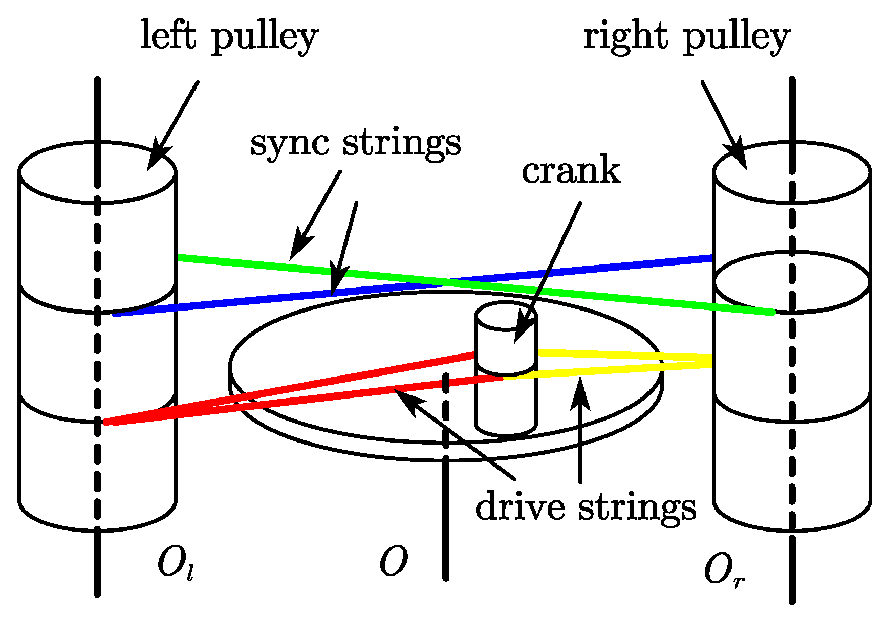
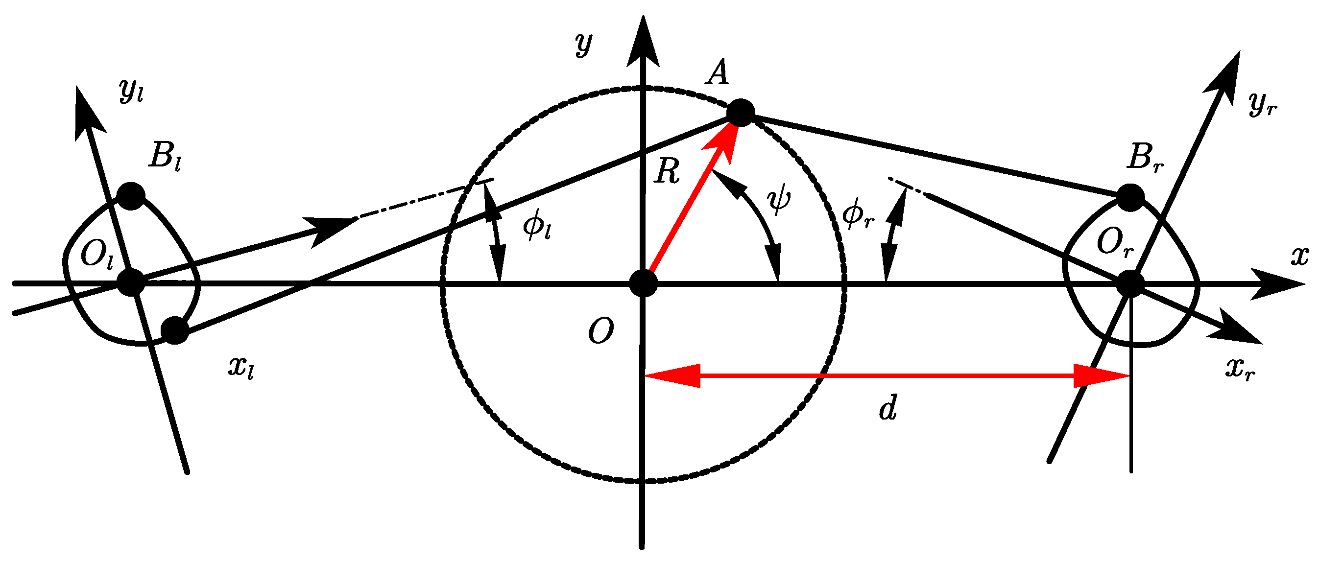
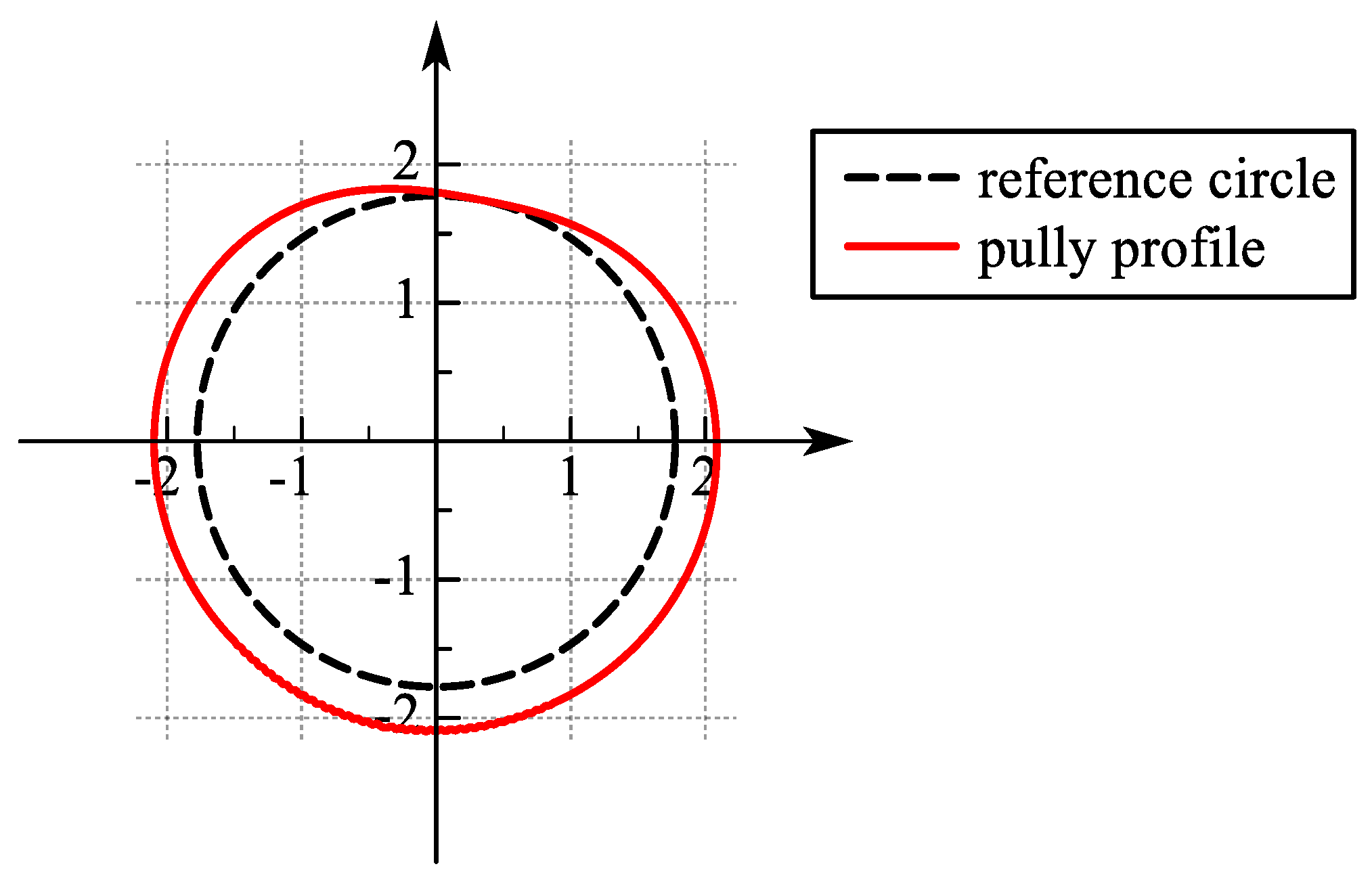
2.1. Flapping Wing Mechanism
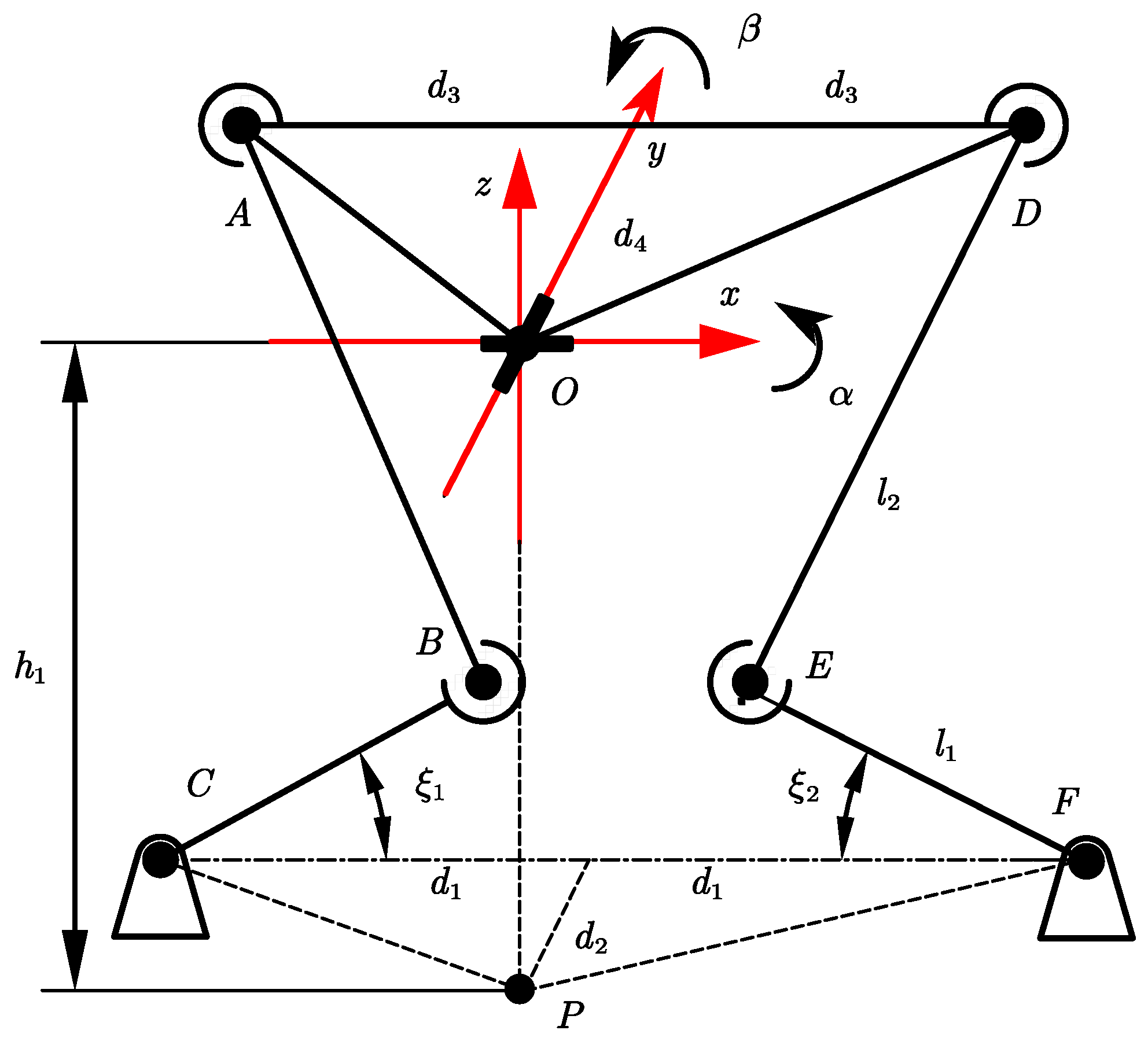
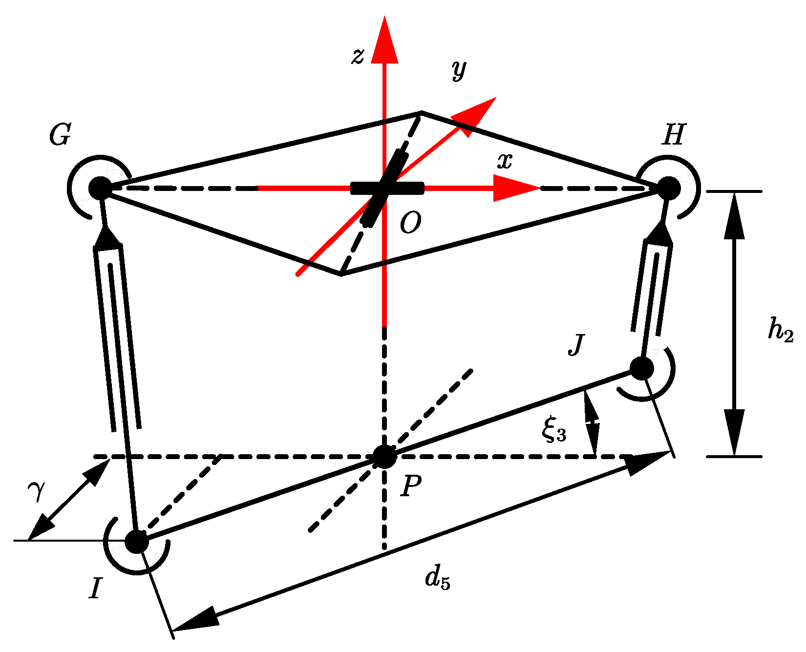
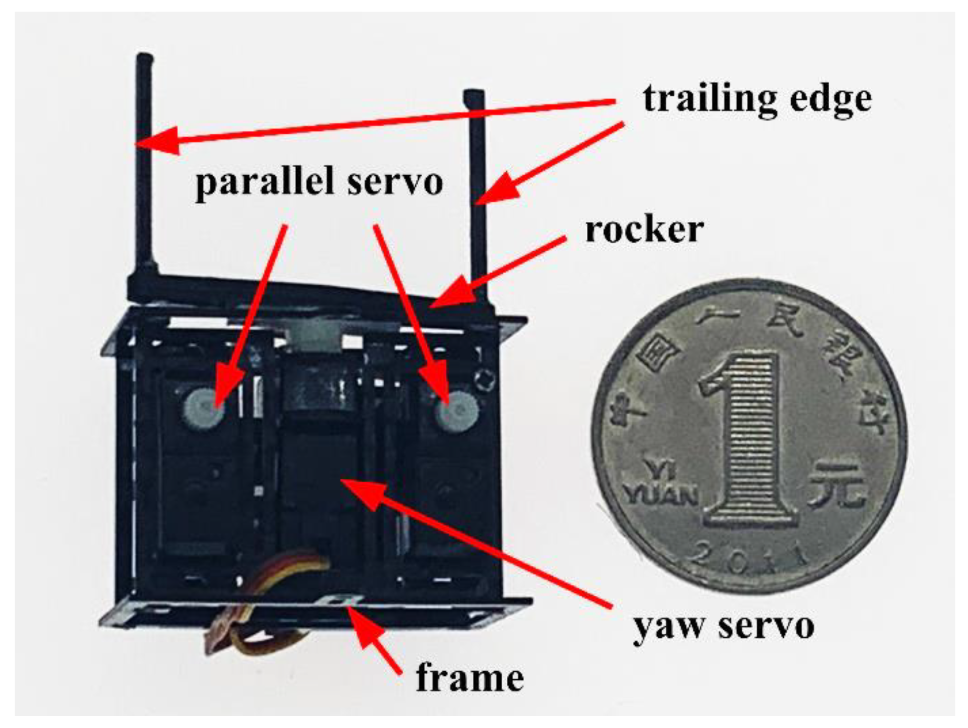
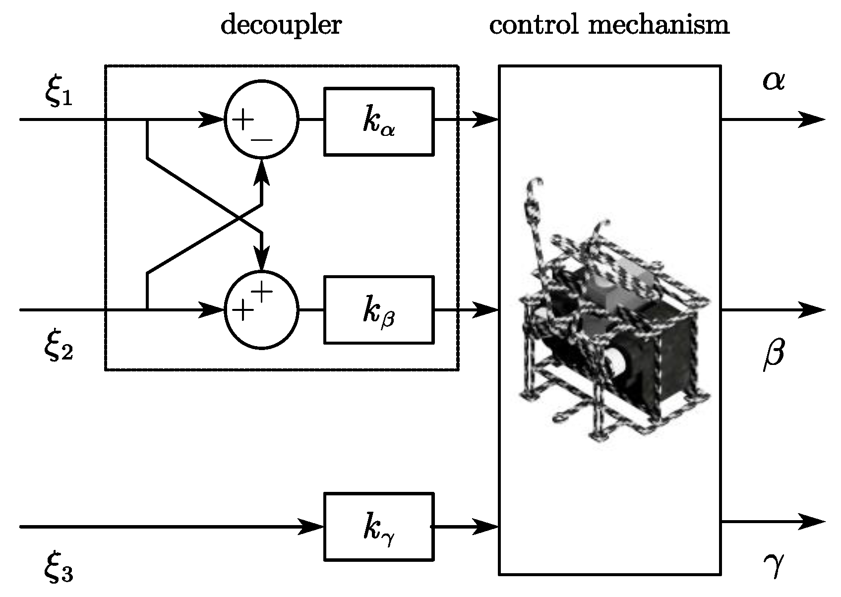
2.2. Control Mechanism
2.3. Wing
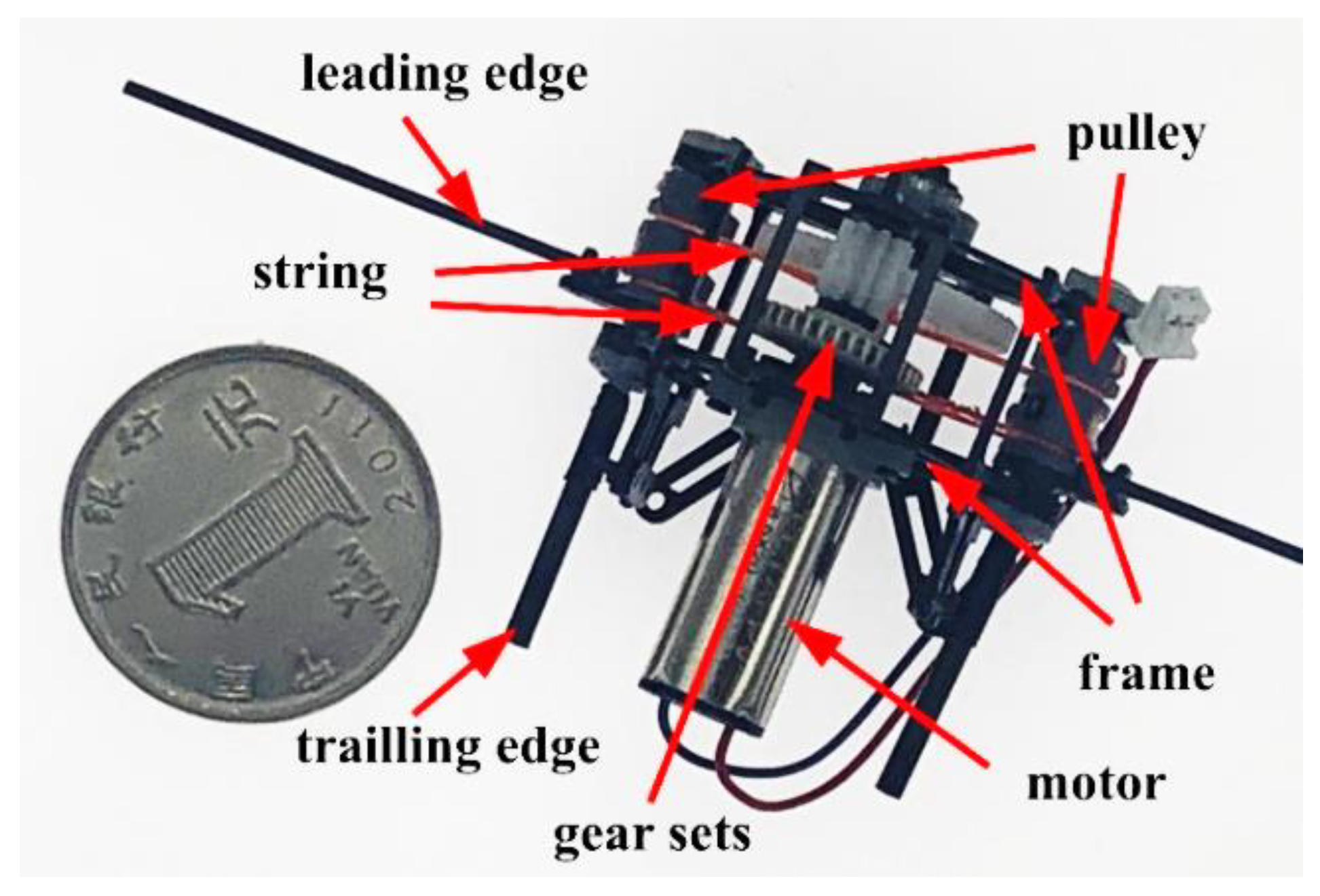
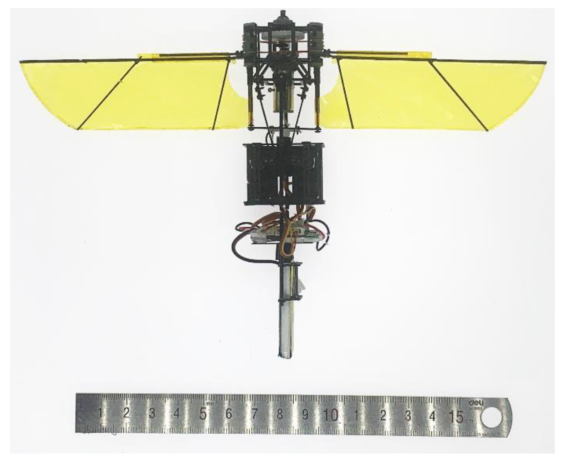
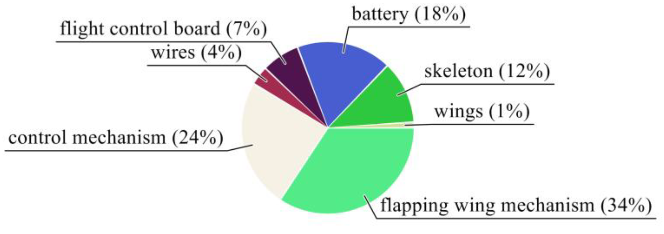
2.4. Prototype
3. Control System
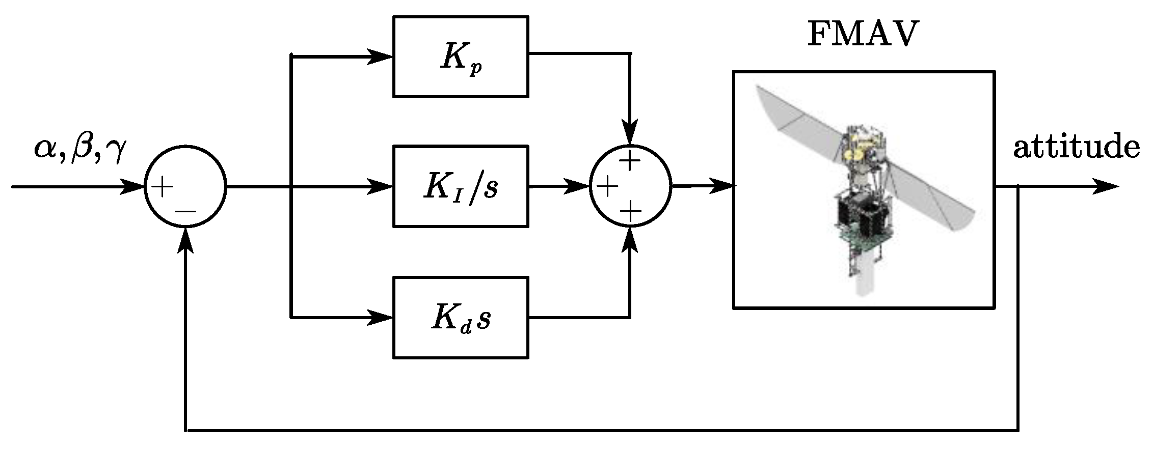
3.1. Attitude Control
3.2. PID Control
4. Experimental Results
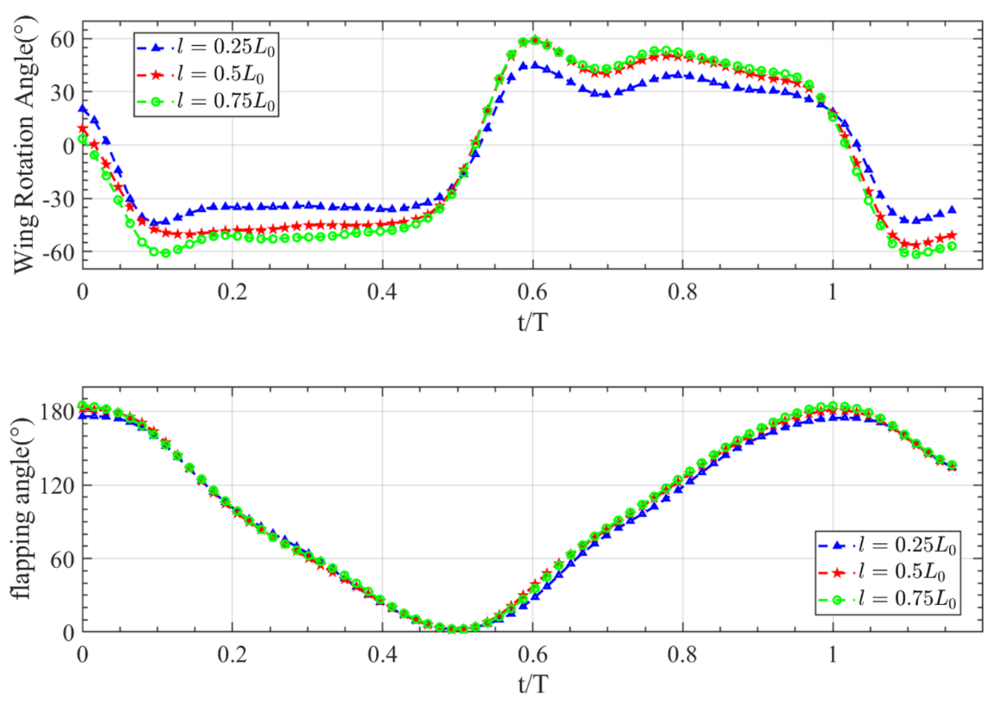
4.1. Wing Kinematics
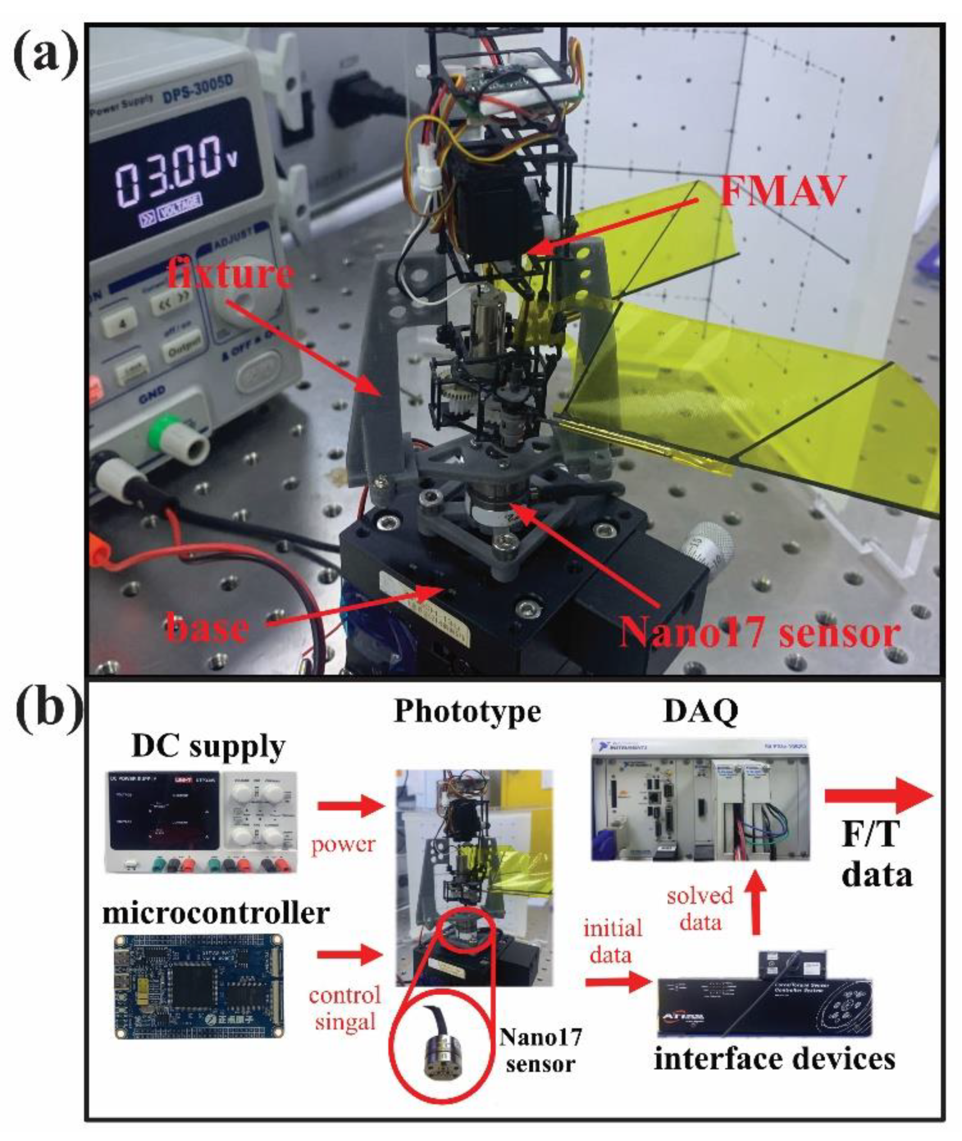
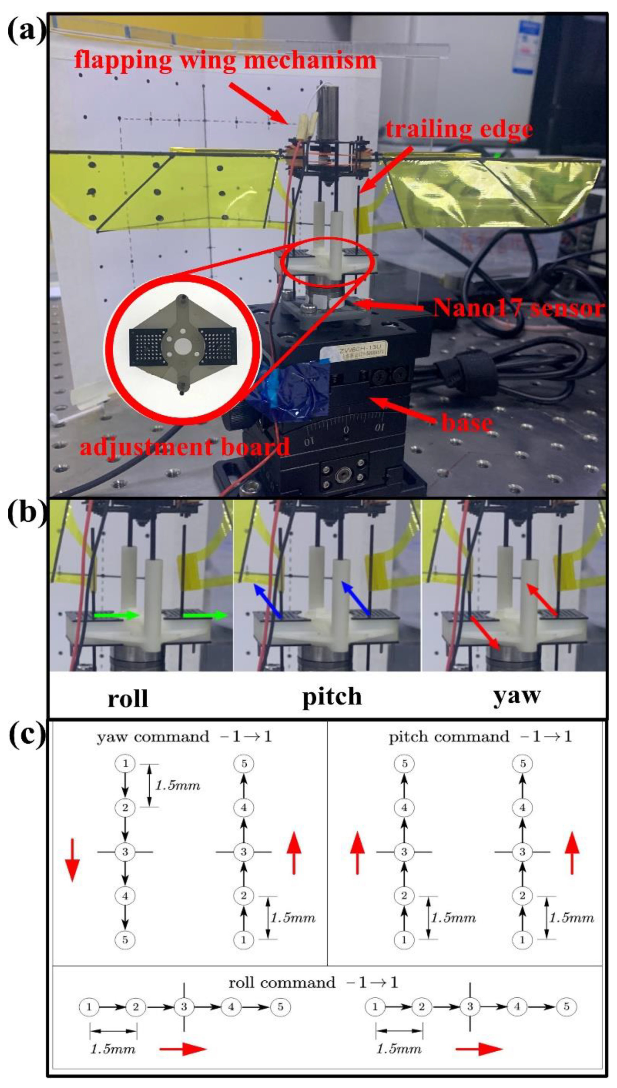
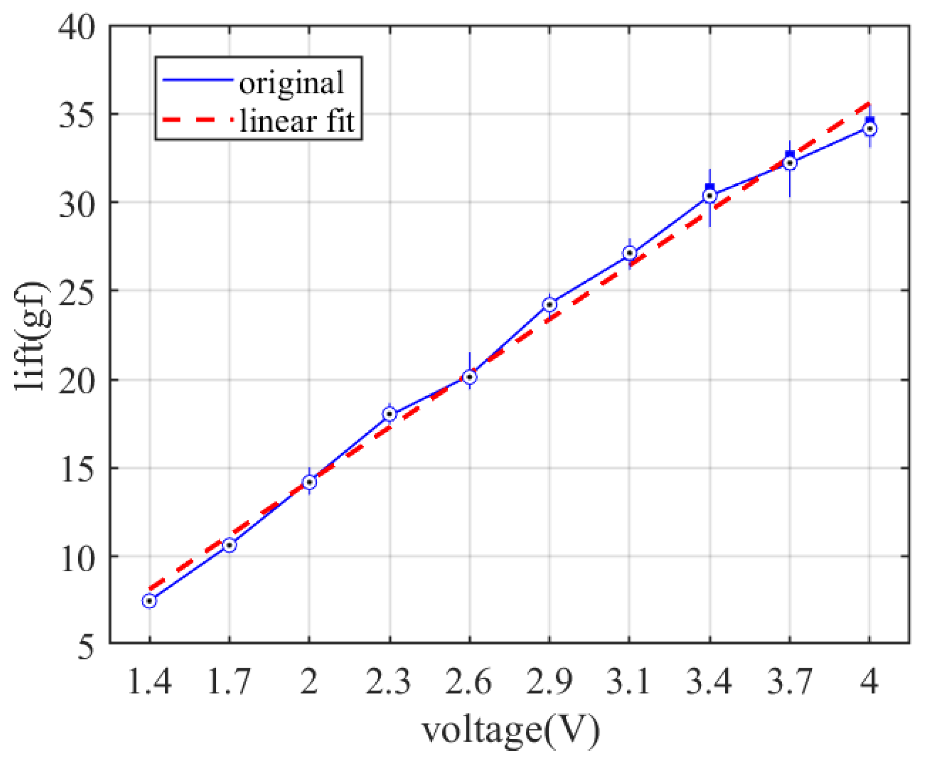
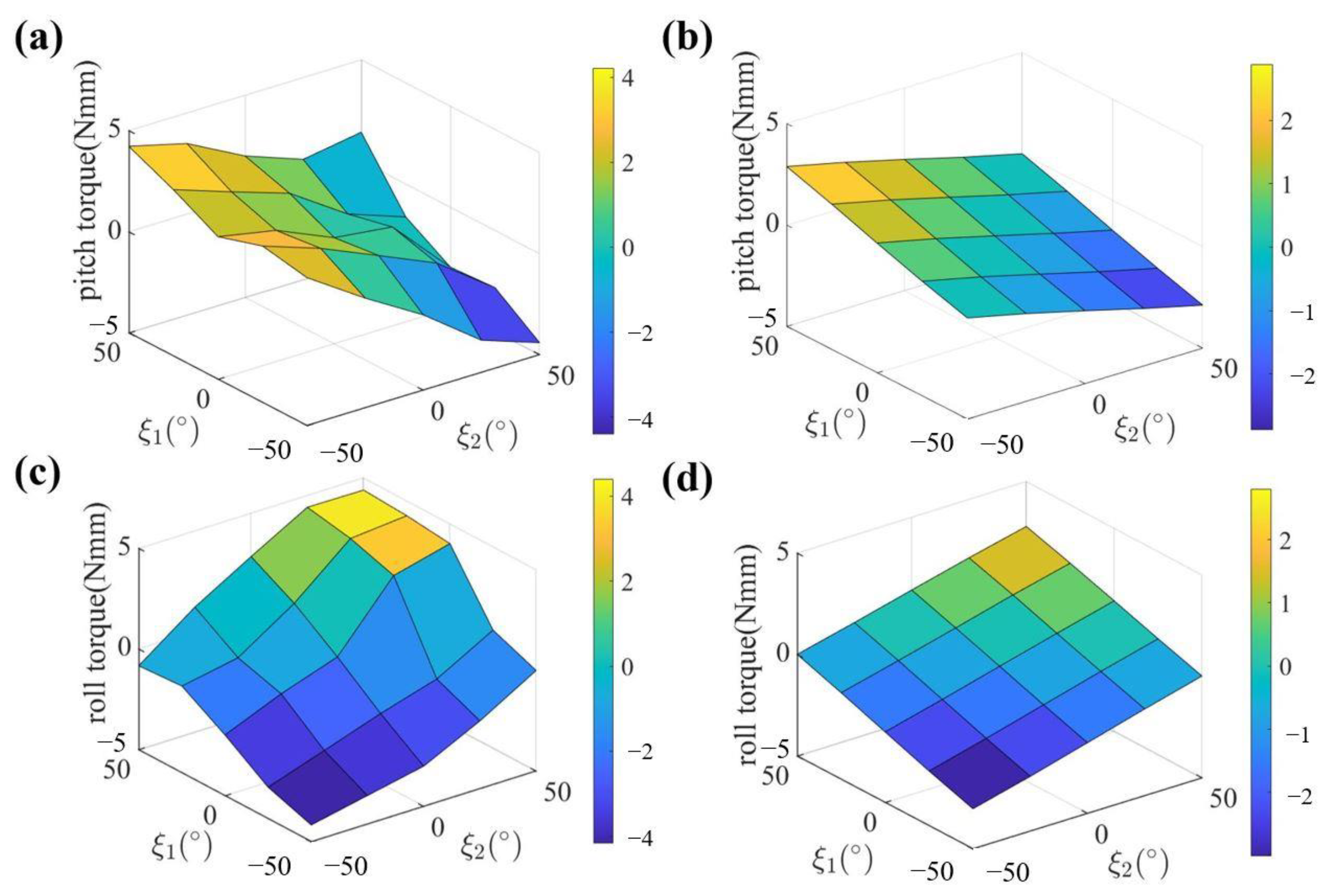
4.2. Force and Torque Measurement
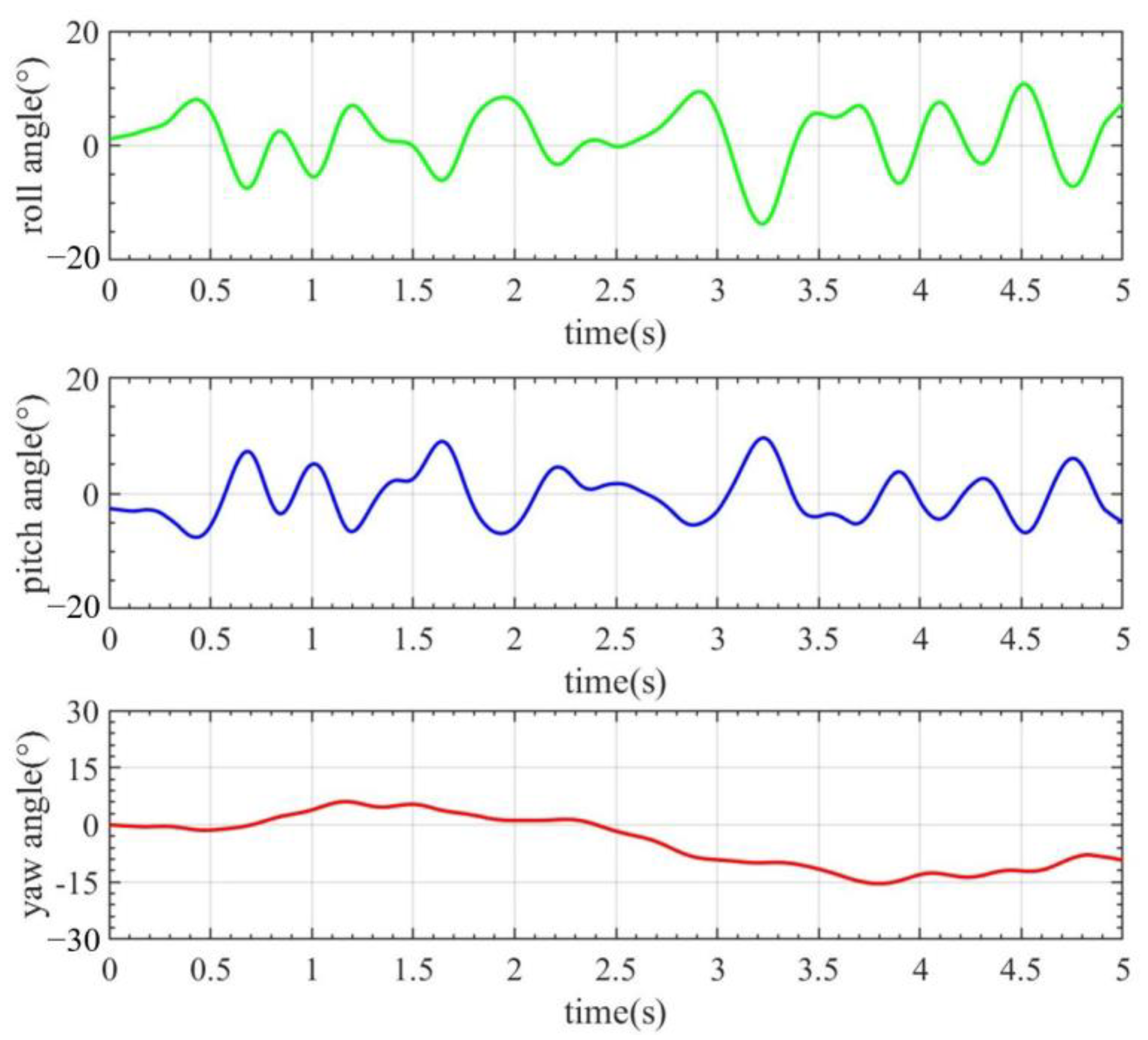
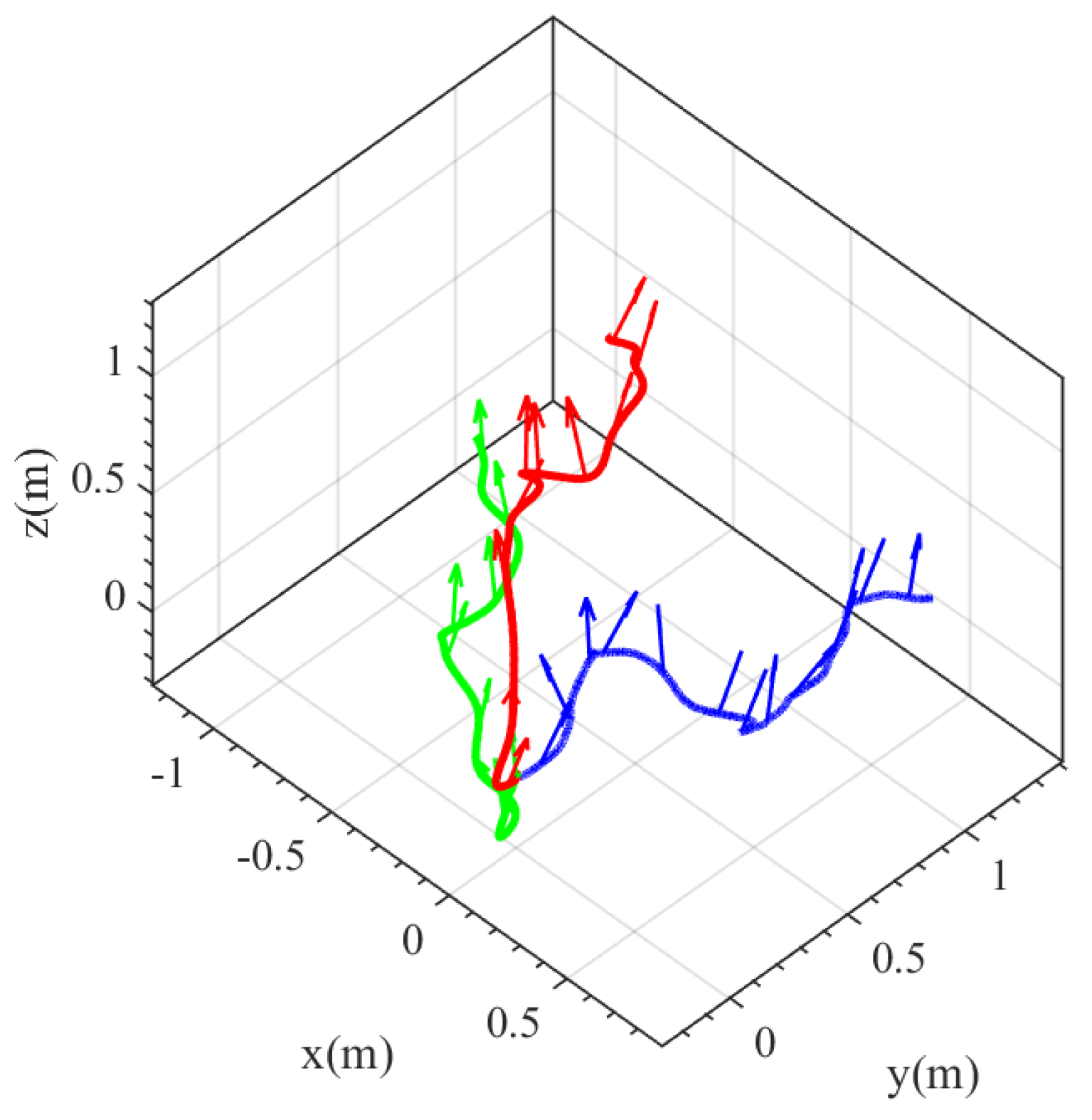
4.3. Flight Test
5. Conclusions
Supplementary Materials
Author Contributions
Funding
Institutional Review Board Statement
Informed Consent Statement
Data Availability Statement
Conflicts of Interest
References
- Sane, S.P.; Dickinson, M.H. The aerodynamic effects of wing rotation and a revised quasi-steady model of flapping flight. J. Exp. Biol. 2002, 205, 1087–1096. [Google Scholar] [CrossRef] [PubMed]
- Nabawy, M.R.A.; Crowthe, W.J. A Quasi-Steady Lifting Line Theory for Insect-Like Hovering Flight. PLoS ONE 2015, 10, e0134972. [Google Scholar] [CrossRef] [PubMed] [Green Version]
- Fernandez-Gamiz, U.; Gomez-Mármol, M.; Chacón-Rebollo, T. Computational Modeling of Gurney Flaps and Microtabs by POD Method. Energies 2018, 11, 2091. [Google Scholar] [CrossRef] [Green Version]
- Basso, M.; Cravero, C.; Marsano, D. Aerodynamic Effect of the Gurney Flap on the Front Wing of a F1 Car and Flow Interactions with Car Components. Energies 2021, 14, 2059. [Google Scholar] [CrossRef]
- Nakata, T.; Liu, H. Aerodynamic performance of a hovering hawkmoth with flexible wings: A computational approach. Proc. R. Soc. B Biol. Sci. 2012, 279, 722–731. [Google Scholar] [CrossRef] [Green Version]
- Shahzad, A.; Tian, F.-B.; Young, J.; Lai, J.C.S. Effects of wing shape, aspect ratio and deviation angle on aerodynamic performance of flapping wings in hover. Phys. Fluids 2016, 28, 111901. [Google Scholar] [CrossRef] [Green Version]
- Ma, K.Y.; Chirarattananon, P.; Fuller, S.B.; Wood, R.J. Controlled Flight of a Biologically Inspired, Insect-Scale Robot. Science 2013, 340, 603–607. [Google Scholar] [CrossRef] [Green Version]
- Roll, J.A.; Cheng, B.; Deng, X. An Electromagnetic Actuator for High-Frequency Flapping-Wing Microair Vehicles. IEEE Trans. Robot. 2015, 31, 400–414. [Google Scholar] [CrossRef]
- Zou, Y.; Zhang, W.; Ke, X.; Lou, X.; Zhou, S. The design and microfabrication of a sub 100 mg insect-scale flapping-wing robot. Micro Nano Lett. 2017, 12, 297–300. [Google Scholar] [CrossRef]
- Zou, Y.; Zhang, W.; Zhang, Z. Liftoff of an Electromagnetically Driven Insect-Inspired Flapping-Wing Robot. IEEE Trans. Robot. 2016, 32, 1285–1289. [Google Scholar] [CrossRef]
- Keennon, M.; Klingebiel, K.; Won, H. Development of the Nano Hummingbird: A Tailless Flapping Wing Micro Air Vehicle. In Proceedings of the 50th AIAA Aerospace Sciences Meeting including the New Horizons Forum and Aerospace Exposition, Nashville, TN, USA, 9–12 January 2012. [Google Scholar]
- De Croon, G. Flapping wing drones show off their skills. Sci. Robot. 2020, 5, eabd0233. [Google Scholar] [CrossRef] [PubMed]
- De Wagter, C.; Tijmons, S.; Remes, B.D.W.; De Croon, G.C.H.E. Autonomous flight of a 20-gram Flapping Wing MAV with a 4-gram onboard stereo vision system. In Proceedings of the 2014 IEEE International Conference on Robotics and Automation (ICRA), Hong Kong, China, 31 May–7 June 2014. [Google Scholar]
- Karásek, M.; Muijres, F.T.; De Wagter, C.; Remes, B.D.W.; De Croon, G.C.H.E. A tailless aerial robotic flapper reveals that flies use torque coupling in rapid banked turns. Science 2018, 361, 1089–1094. [Google Scholar] [CrossRef] [PubMed] [Green Version]
- Coleman, D.; Benedict, M.; Hrishikeshavan, V.; Chopra, I. Design, Development and Flight-Testing of a Robotic Hummingbird. In Proceedings of the American Helicopter Society 71st Annual Forum, Virginia Beach, VA, USA, 5–7 May 2015. [Google Scholar]
- Phan, H.V.; Aurecianus, S.; Au, T.K.L.; Kang, T.; Park, H.C. Towards the Long-Endurance Flight of an Insect-Inspired, Tailless, Two-Winged, Flapping-Wing Flying Robot. IEEE Robot. Autom. Lett. 2020, 5, 5059–5066. [Google Scholar] [CrossRef]
- Phan, H.V.; Aurecianus, S.; Kang, T.; Park, H.C. KUBeetle-S: An insect-like, tailless, hover-capable robot that can fly with a low-torque control mechanism. Int. J. Micro Air Veh. 2019, 11, 175682931986137. [Google Scholar] [CrossRef] [Green Version]
- Phan, H.V.; Kang, T.; Park, H.C. Design and stable flight of a 21 g insect-like tailless flapping wing micro air vehicle with angular rates feedback control. Bioinspir. Biomim. 2017, 12, 036006. [Google Scholar] [CrossRef]
- Phan, H.V.; Nguyen, Q.V.; Truong, Q.T.; Truong, T.V.; Park, H.C.; Goo, N.S.; Byun, D.; Kim, M.J. Stable vertical takeoff of an insect-mimicking flapping-wing system without guide implementing inherent pitching stability. J. Bionic Eng. 2012, 9, 391–401. [Google Scholar] [CrossRef]
- Tu, Z.; Fei, F.; Zhang, J.; Deng, X. An At-Scale Tailless Flapping-Wing Hummingbird Robot. I. Design, Optimization, and Experimental Validation. IEEE Trans. Robot. 2020, 36, 1511–1525. [Google Scholar] [CrossRef]
- Nguyen, Q.-V.; Chan, W.L. Development and flight performance of a biologically-inspired tailless flapping-wing micro air vehicle with wing stroke plane modulation. Bioinspir. Biomim. 2018, 14, 016015. [Google Scholar] [CrossRef]
- Roshanbin, A.; Altartouri, H.; Karásek, M.; Preumont, A. COLIBRI: A hovering flapping twin-wing robot. Int. J. Micro Air Veh. 2017, 9, 270–282. [Google Scholar] [CrossRef] [Green Version]
- Gosselin, C.M.; Hamel, J.F. The Agile Eye: A High-Performance Three-Degree-of-Freedom Camera-Orienting Device. In Proceedings of the IEEE International Conference on Robotics & Automation, San Diego, CA, USA, 8–13 May 1994; pp. 781–786. [Google Scholar]
- McClintock, H.; Temel, F.Z.; Doshi, N.; Koh, J.S.; Wood, R.J. The milliDelta: A high-bandwidth, high-precision, millimeter-scale Delta robot. Sci. Robot. 2018, 3, eaar3018. [Google Scholar] [CrossRef] [Green Version]
- Gong, D.; Lee, D.; Shin, S.; Kim, S. String-based flapping mechanism and modularized trailing edge control system for insect-type FWMAV. Int. J. Micro Air Veh. 2019, 11, 175682931984254. [Google Scholar] [CrossRef]
- Phan, H.V.; Truong, Q.T.; Au, T.K.L.; Park, H.C. Effect of Wing Kinematics Modulation on Aerodynamic Force Generation in Hovering Insect-mimicking Flapping-wing Micro Air Vehicle. J. Bionic Eng. 2015, 12, 539–554. [Google Scholar] [CrossRef]
- Wang, C.; Zhou, C.; Zhu, X. Influences of flapping modes and wing kinematics on aerodynamic performance of insect hovering flight. J. Mech. Sci. Technol. 2020, 34, 1603–1612. [Google Scholar] [CrossRef]
- Ha, N.S.; Truong, Q.T.; Phan, H.V.; Goo, N.S.; Park, H.C. Structural Characteristics of Allomyrina Dichotoma Beetle’s Hind Wings for Flapping Wing Micro Air Vehicle. J. Bionic Eng. 2014, 11, 226–235. [Google Scholar] [CrossRef]
- Syam, S.N.; Ahmed, R.A.; Varghese, J.P.; Gopinath, S.; Paulraj, J.; Muthukumar, M. Experimental investigation on lift generation of flapping MAV with insect wings of various species. Aircr. Eng. Aerosp. Technol. 2019, 92, 139–144. [Google Scholar] [CrossRef]
- Phan, H.V.; Park, H.C. Design and evaluation of a deformable wing configuration for economical hovering flight of an insect-like tailless flying robot. Bioinspir. Biomim. 2018, 13, 036009. [Google Scholar] [CrossRef]
- Ha, N.S.; Nguyen, Q.V.; Goo, N.S.; Park, H.C. Static and Dynamic Characteristics of an Artificial Wing Mimicking an Allomyrina Dichotoma Beetle’s Hind Wing for Flapping-Wing Micro Air Vehicles. Exp. Mech. 2012, 52, 1535–1549. [Google Scholar] [CrossRef]
- Shen, Y.; Zhang, W.; Mou, J.; Xu, C.; Xu, J.; Chen, Z.; Shu, T. Experimental System Design and Performance Tests of a Bio-inspired Flapping Wing Micro Air Vehicle. In Proceedings of the 2020 3rd International Conference on Unmanned Systems (ICUS), Harbin, China, 27–28 November 2020. [Google Scholar]
- Hedrick, T.L. Software techniques for two- and three-dimensional kinematic measurements of biological and biomimetic systems. Bioinspir. Biomim. 2008, 3, 6. [Google Scholar] [CrossRef]
- Kim, J.H.; Park, C.Y.; Jun, S.M.; Parker, G.; Yoon, K.J.; Chung, D.K.; Paik, I.H.; Kim, J.R. Instrumented flight test of flapping micro air vehicle. Aircr. Eng. Aerosp. Technol. 2013, 85, 326–339. [Google Scholar] [CrossRef]
- Chen, Z.; Zhang, W.; Mou, J.; Zheng, K. Horizontal take-off of an insect-like FMAV based on stroke plane modulation. Aircr. Eng. Aerosp. Technol. 2022. online ahead of print. [Google Scholar] [CrossRef]


| var | |||||||
|---|---|---|---|---|---|---|---|
| Length (mm) | 7 | 35 | 8 | 9 | 9 | 9 | 36 |
| Property | Value |
|---|---|
| Flapping frequency | 25 Hz |
| wingspan | 21 cm |
| weight | 28 g |
| battery capacity | 250 mah |
| power | 11 W |
| max lift | 34 gf |
Publisher’s Note: MDPI stays neutral with regard to jurisdictional claims in published maps and institutional affiliations. |
© 2022 by the authors. Licensee MDPI, Basel, Switzerland. This article is an open access article distributed under the terms and conditions of the Creative Commons Attribution (CC BY) license (https://creativecommons.org/licenses/by/4.0/).
Share and Cite
Chen, Z.; Zhang, W.; Mou, J.; Zhao, J. Development of an Insect-like Flapping-Wing Micro Air Vehicle with Parallel Control Mechanism. Appl. Sci. 2022, 12, 3509. https://doi.org/10.3390/app12073509
Chen Z, Zhang W, Mou J, Zhao J. Development of an Insect-like Flapping-Wing Micro Air Vehicle with Parallel Control Mechanism. Applied Sciences. 2022; 12(7):3509. https://doi.org/10.3390/app12073509
Chicago/Turabian StyleChen, Zihao, Weiping Zhang, Jiawang Mou, and Jiaxin Zhao. 2022. "Development of an Insect-like Flapping-Wing Micro Air Vehicle with Parallel Control Mechanism" Applied Sciences 12, no. 7: 3509. https://doi.org/10.3390/app12073509
APA StyleChen, Z., Zhang, W., Mou, J., & Zhao, J. (2022). Development of an Insect-like Flapping-Wing Micro Air Vehicle with Parallel Control Mechanism. Applied Sciences, 12(7), 3509. https://doi.org/10.3390/app12073509