Abstract
In the present paper, the computational fluid dynamics (CFD) numerical simulation was utilized to investigate the effectiveness of the transverse traveling wave wall (TWW) method with the expectation of inhibiting the vortex shedding from a fixed circular cylinder. We mainly focused on the variations of four kinds of wave propagation directions, five different maximum wave amplitudes and ten different wave velocities for suppressing vortices shedding and aerodynamic forces. The aerodynamic coefficients and vortex structures under different propagation directions, wave amplitudes, wave numbers and wave velocities were investigated in detail. The results demonstrate that the alternate wake behind the cylinder can be effectively eliminated resorting to the “Downstream” propagating TWW. The mean drag coefficient is positively associated with wave velocity. Drag and lift coefficients remain relatively stable at different wave amplitudes. When the velocity ratio (wave velocity divided by incoming velocity) is 1.5, the lift coefficient fluctuation decreases to the minimum. In contrast, the optimal combination of control parameters under the present Reynolds number is concluded with “Downstream” propagating direction, maximum wave amplitude ratio of 0.02, and velocity ratio of 1.5.
1. Introduction
Fluid flow around a cylinder is a universal phenomenon in engineering practice, i.e., heat exchanger tubes, marine cables, high-rises, and civil engineering structures. Vortex shedding behind bluff cylinders is the cause of vortex-induced vibration (VIV) which can result in structural damage under certain unfavorable conditions. In addition, there have been a variety of investigations about vortex-induced vibration from different perspectives in recent years [1,2]. Eliminating the alternating shedding vortices in the cylinder wake and suppressing the cylinder vibration are of important significance.
Fluid has a huge influence on bluff body structures, and there are many relative research [3,4,5]. Studies on flow control of bluff body have specified a new orientation for the flow control problems, and they have gained more and more concerns in recent years. Controlling methods can be mainly divided into two types: passive control and active control. Passive flow control could change the flow conditions to achieve the goal of flow control without consuming any external energy [6,7,8,9,10]. Another flow control method is active flow control, which requires external energy infused into the flow field. Moreover, active flow control could introduce the proper perturbation to change the inner flow mode. Several active flow control methods have been investigated to suppress vibration as well as improve aerodynamic performance, i.e., drag reduction, using wall vibration [11,12], suction and injection [13,14,15,16], momentum injection [17,18,19,20], bionic control method of traveling wave wall, etc.
The TWW is one of the bionic based flow control methods and it has been developing rapidly in recent years. The boundary layer near the rigid wall comes into existence when the viscous fluid flows pass the wall. However, making the cylinder surface to be flexible or movable may help to weaken the boundary layer.
The “fluid roller bearing” (FRB) effects of the axisymmetric TWW was used by Yang and Wu [21] to sharp into a series of vortex rings. The main flow was separated from the near-wall flow accompanied by friction drag and pressure drag significantly reduced. Wu et al. [22] carried out a numerical simulation to find out the proper parameter (wave amplitude, wavelength and ratio of wave velocity to incoming velocity) for the FRB effects on infinite and finite two-dimensional TWW. Large flow separation was eliminated after applying TWW on airfoils, and the vortex shedding of streamline airfoils with a large wind attack angle was restrained to provide more lift. Wu et al. [23] proposed a transverse traveling wave (TTW) control method to manipulate the unsteady flow around a circular cylinder at Re = 500. A fluid FRB was introduced in this method, and the vortex shedding was eliminated because the global flow remained attached to the surface. Xu et al. [24] simulated the rear section of a cylinder with TWW, and the cylinder was elastically mounted with two degrees of freedom. The simulation took fixed wave amplitude, wave number and ratio of wave velocity to incoming velocity. In addition, the whole process was completely simulated starting with flow around the fixed cylinder, to the oscillating cylinder, and finally to the oscillating cylinder with TWW.
In the present paper, TWW was placed on the rear section of a fixed cylinder, and the CFD numerical simulation was adapted to investigate the influencing factors for suppressing the cylinder oscillating wake. The TWW was activated when the alternating shedding vortex behind the fixed circular could be stably observed in the present numerical simulation. There are several steps we need to comply with as per control variate technique. Firstly, fixed velocity ratio and maximum wave amplitude were used to measure the control effect of four kinds of TWW propagation direction for suppressing the oscillating wake. Then, the most effective propagation direction was selected, based on which we forward studying the controlling effectiveness of 5 different wave amplitudes, 4 different wave numbers and 10 different wave velocities. The control effect under various influencing factors was elaborated by comparing the characteristic values, aerodynamic force time histories and the wake flow patterns.
2. Numerical Model and Validation
2.1. Governing Equations and TWW
The governing equations of two-dimensional incompressible flow in a Cartesian coordinate system can be written as follows.
where is the velocity components, i.e., is the velocity component at the inline flow direction and is the velocity component at the cross-flow direction, denotes the kinematic viscosity coefficient, is the fluid density, and denotes the pressure in flow field.
As shown in Figure 1, The transverse traveling wave at the rear section of cylinder was established, i.e., the transverse traveling wave can propagate from both point B and C to point A at the same time.
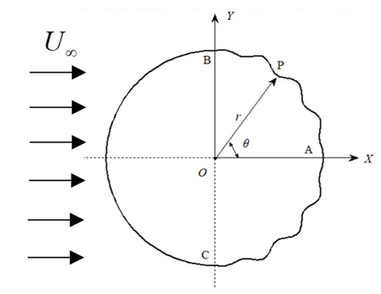
Figure 1.
Schematic of fixed circular cylinder with TWW.
The origin O is positioned at the center of the plane polar coordinate system (r, θ), and the wave equations of the TWW can be written as,
where is the radius of the standard circular cylinder without any traveling wave, D is the diameter of the cylinder, is the vibration amplitude of each point on the TWW, is the wave number, is the arc length from point A on the cylinder rear edge to any point P on the TWW, is the wave velocity, is the time, is the wave length, is the maximum wave amplitude, is the wave number in circle. In the first wave, the amplitude increases linearly from 0; In the end wave, the amplitude decreases linearly to 0, while other intermediate waves have the same amplitude as the complete waveform, as shown in Equation (4). The TWW connect smoothly with the non-moving cylinder surface in this configuration.
2.2. Computational Domain and Boundary Conditions
Figure 2 shows the grid distribution and the computational domain. The computational domain is a rectangle area with a length of 60D and a width of 40D, and the center of the cylinder is at the coordinate origin. The cylinder diameter is 0.12 m. The upstream inlet is 20D ahead of the coordinate origin, and the downstream outlet is 40D after the coordinate origin. The distances between either of the upside and downside and the coordinate origin are 20D. Unstructured grid is adopted to discretize the computational domain into four layers. The grids in the regions with large gradients of flow parameters are locally refined, i.e., the region near cylinder surface and wake region. The geometric model and meshing are performed by pre-processing software ICEM.
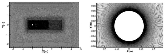
Figure 2.
Grid distribution and computational domain near the cylinder surface.
The boundary conditions are set up as follows, the inlet is set as the velocity-inlet with a uniform velocity , the outlet is set as the pressure-outlet with the relative pressure of 0, the upper and lower sides are set as the symmetry boundary, and the cylinder surface is set as the no-slip wall.
The numerical calculations are carried out with a Reynold number of , and the turbulence flow is calculated by SST k-ω model. SIMPLE algorithm is adopted to calculate the coupling between the pressure and velocity fields. The pressure interpolation format is set as “Standard”. The second-order upwind scheme is used for the momentum discretizing because of its accuracy and stability. During the solution process, the convergence residual standard of continuity equation is 1.0 × 10⁻⁶, and the convergence residual standard of momentum equation and turbulence parameters is 3.0 × 10⁻⁷.
The CFD general software Fluent is used to calculate the flow around a fixed cylinder. Firstly, the governing Equations (1) and (2) are solved to obtain the flow characteristics around the cylinder, and then the aerodynamic coefficient of the cylinder is obtained. When the amplitude of the aerodynamic coefficient is stable (t = 1.8 s), TWW is activated. The wave Equation (3) of traveling wave is solved by User Defined Function (UDF) in Fluent, and the radial velocity at any point P in Figure 1 can be obtained according to Equation (3), and then the radial velocity is decomposed into the x direction velocity and the y direction velocity. The DEFINE_GRID_MOTION macro of UDF is used to assign the velocity for all grid points on the rear semi-cylindrical surface, and the motion of cylinder surface grids are realized by the dynamic mesh technique. When the grids are updated to the specified position, the flow field is calculated to converge with this shape as the boundary, and then the calculation of the next time step begins. This loop calculation ends until the TWW achieves a significant wake control effect.
2.3. Validity Investigation
The grid and time step independence verification were carried out because the mesh size and the time step determine the accuracy of CFD computational results. The comparisons of the global parameters for the grid and time step independences studies are shown in Table 1 and Table 2. In the tables, is the number of nodes for 1/4 circle, is the total number of the mesh, and is the time step. The global parameters include the fluctuating lift coefficient , the mean drag coefficient , the fluctuating drag coefficient , the Strouhal number , and the minimum, mean and maximum values , and , respectively. In order to guarantee the correctness of the turbulence simulation results and sufficient amount of mesh in the viscous sublayer, the should be less than 11.63 which is the demarcation point between the log-law region and the viscous sublayer recommended by Versteeg and Malalasekera [25].

Table 1.
Comparisons of the global parameters for the grid independence study.
Table 2.
Comparisons of the global parameters for the time step independence study.
Through comparison and analyzation of the global parameter results, and were adopted in the final results discussion. Current results accompanied with some previous simulation and experimental results [26,27,28,29,30,31,32,33,34,35,36] for the flow around a single cylinder are shown in Figure 3. The mean drag coefficient versus Reynolds is shown in Figure 3a, and it can be observed that is very close to previous results at similar Re range. The in the previous 3D flow experiment is less than that in this paper at similar Re range. In the present 2D numerical simulation, the computational domain height is extraordinarily small, so the 3D flow in spanwise direction cannot be fully developed. Thus, the present results are closer to the 2D flow results [28,34,35], as shown in Figure 3b. From the previous comparison, it can be concluded that the present numerical model and grids are reliable and have good reference value for further research of TWW flow control.
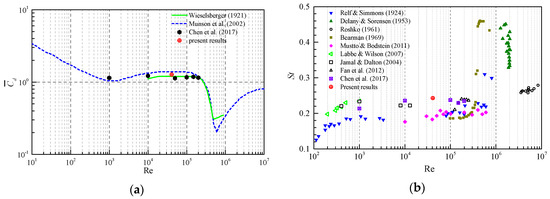
Figure 3.
Comparisons of aerodynamic coefficient and the Strouhal number with previous results. (a) versus Re. (b) versus Re.
3. Results and Discussion
3.1. Influence of Different Propagation Directions
The control effectiveness of 4 types of TWW propagation should be considered first. The four propagation directions include the “Downstream”, the “Upstream”, the “Corotating-Clockwise” and the “Corotating-Counterclockwise”, as shown in Figure 4. During calculation process, the effects of the TWW propagation directions are considered under fixed velocity ratio , wave number , and maximum wave amplitude . This numerical simulation begins with the flow around a fixed cylinder (FR). The TWW is activated to control the flow field after the flow field is brought into stability with alternating shedding vortices. The aerodynamic coefficients and vortex shedding patterns before and after activating the TWW could serve as a good measurement for the control effect of TWW control method.
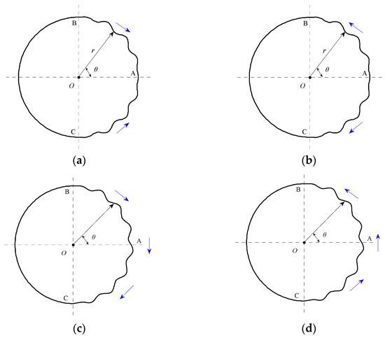
Figure 4.
Four types of propagation direction of TWW. (a) Downstream. (b) Upstream. (c) Corotating-Clockwise. (d) Corotating-Counterclockwise.
The time histories of lift and drag coefficient for the TWW cylinder with the four different propagation directions are shown in Figure 5. When , TWW was not activated, the result of FR was obtained. When , TWW was activated, the suppression effect of TWW on the vortex shedding and wake under the four different propagation directions can be obtained.
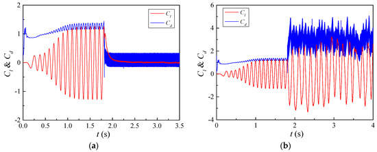
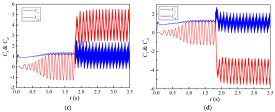
Figure 5.
Lift and drag coefficient time history curves under various propagation directions. (a) Downstream. (b) Upstream. (c) Corotating-Clockwise. (d) Corotating-Counterclockwise.
Figure 5 shows that the lift coefficient fluctuation reduces dramatically only when traveling wave propagates in the downstream direction. It indicates that the TWW propagating downstream has the effect of eliminating Vortex Street. In addition, the mean drag coefficient decreases at this propagation direction, while the fluctuating drag coefficient increases dramatically, as shown in Figure 5a. Figure 5b shows that the fluctuating lift coefficient and mean drag coefficient increase significantly when traveling wave propagates in the upstream direction. It illustrates that the traveling wave propagating upstream enhances the wake behind the cylinder. The drag coefficient fluctuation increases, and the mean lift coefficient varies significantly when traveling wave co-propagates along the cylinder rear surface. When traveling wave Co-rotates clockwise, the mean lift coefficient increases significantly to a positive value, as shown in Figure 5c. When traveling wave Co-rotates counterclockwise, the mean lift coefficient decreases significantly to a negative value, as shown in Figure 5d. It indicates that there is a negative pressure zone on the upper or lower surface with these two propagation directions, and the oscillating wake of traveling wave cylinder cannot be eliminated.
The mean value reflects the variant characteristics within a period, and the fluctuation value (root-mean-square, RMS) reflects the discrete degree of the variant. Before activating the TWW, the mean lift coefficient approximates 0 and is 0.921, the mean drag coefficient is 1.267 and is 0.081. The time history curves of lift and drag coefficients for uncontrolled cylinder are taken for reference in the following parts to measure the influence of different control parameters on the control effect. Figure 6 shows the lift and drag coefficients characteristics with different traveling wave propagation directions, while the dashed curves inside the same figure demonstrate the results of the standard circular cylinder. As shown in Figure 6a, approaches to 0 for “Downstream” and “Upstream” propagation direction, while the increases dramatically to 3.917 and −4.057 for co-propagations. For the “Downstream” propagation, the approaches to 0, which indicates that the cylinder oscillating wake is eliminated by TWW. For the “Upstream” propagation, increases dramatically to 1.825. In addition, for the co-propagations is close to that of the standard circular cylinder. These illustrate that the other three propagations are not able to suppress the cylinder wake vortex except “Downstream”. Figure 6b shows that the fluctuating drag coefficients vary between 0.172 and 0.763 in various propagation directions, and all of them are larger than that of the standard circular cylinder, which means that TWW leads to a larger amplitude fluctuating drag. For “Downstream” propagation, decreases dramatically to −0.152, meaning the cylinder is subjected to reverse thrust due to TWW. For “Upstream” propagation, increases dramatically to 2.809, i.e., the inline flow drag increases dramatically. The of other two propagation directions equal to 0.905 and 0.902, respectively, which are slightly lower than the standard circular cylinder. Compared with the standard circular cylinder results, and of “Downstream” propagation decreases by 99.48% and 112%, respectively. It illustrates the cylinder wake oscillation in FR stage can be eliminated by the TWW propagating downstream.
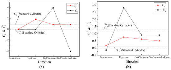
Figure 6.
Characteristic values of lift and drag coefficient for different propagation directions. (a) . (b) .
The vorticity contours surrounding TWW cylinder with “Downstream” propagation are shown in Figure 7. In the interval , the traveling wave was not activated, and the vortex sheds from both side of the cylinder alternately, as shown in Figure 7a. Figure 7b shows that the TWW activated shortly has little effects, and the separated free shear layer still rolls into vortices. Form Figure 7c–g, as time advanced, the control effect of TWW became more obvious, and the vortex street appeared in uncontrolled cylinder was eliminated. The shear layer detaches from the cylinder surface, and then enters the wake region without rolling into vortices due to the “fluid roller bearing” (FRB) effect of TWW, and the vorticity is distributed steadily and symmetrically in the cylinder wake region, which means that the TWW cut off the energy source for generating vortex. When , the TWW eliminates oscillating wakes of the cylinder successfully.
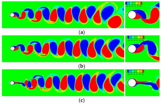
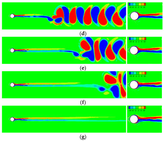
Figure 7.
The contour of vorticity when wave starts at . (a) t = 1.80 s. (b) t = 1.96 s. (c) t = 2.16 s. (d) t = 2.31 s. (e) t = 2.46 s. (f) t = 2.61 s. (g) t = 2.97 s.
In addition to the “Downstream” propagation, the rest three kinds of propagations are less effective in eliminating the cylinder oscillating wake, which can be seen from the vorticity contours obtained after activating TWW, as shown in Figure 8 and Figure 9. In Figure 8, the vortices in the wake formed by FR are replaced by stronger vortices, so that the fluctuating lift coefficient and the mean drag coefficient increase dramatically. In Figure 9, an overall downward vortex street is formed in the cylinder wake region because of the “Corotating-Clockwise” traveling wave. In addition, the wake for the “Corotating-Counterclockwise” traveling wave induces an overall upward vortex street, which is opposite to that in Figure 9. For both clockwise and counterclockwise propagation directions, the TWW is activated at the same time (t = 1.8 s), and the initial state of the flow field controlled by the TWW propagating in the two directions is exactly the same. If the clockwise and counterclockwise TWWs are activated at opposite phases of the lift coefficient oscillations, it is expected to obtain a mirror-symmetrical flow field and exactly equal aerodynamic results. The choice of TWW activating phase is an important reason for the slight difference in the aerodynamic statistic values of the circular cylinder with the two different propagation directions of TWW, as shown in Figure 6.
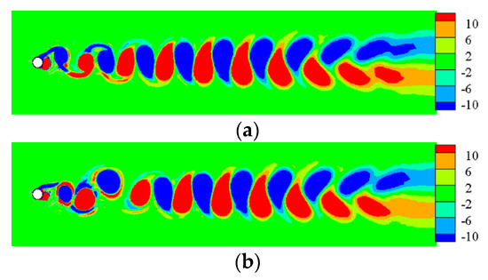
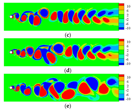
Figure 8.
The vorticity contours of TWW cylinder with “Upstream” propagation. (a) t = 2.16 s. (b) t = 2.31 s. (c) t = 2.46 s. (d) t = 2.61 s. (e) t = 2.97 s.
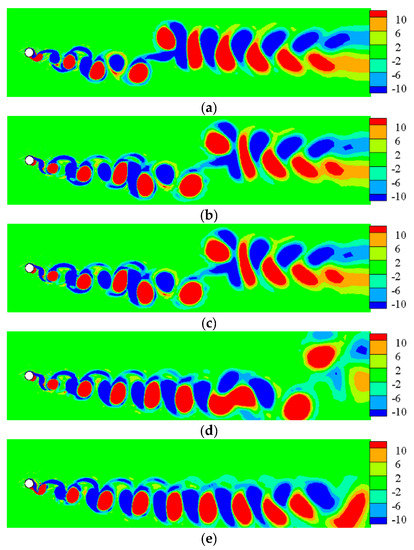
Figure 9.
The vorticity contours of TWW cylinder with “Corotating-Clockwise” propagation. (a) t = 2.16 s. (b) t = 2.31 s. (c) t = 2.46 s. (d) t = 2.61 s. (e) t = 2.97 s.
3.2. Influence of Different Wave Amplitudes
The “Downstream” propagation direction is therefore selected as the base to study the influence of traveling wave amplitude, the fixed TWW velocity ratio is taken as 2.0, and the wave number per quarter circle is taken as 4. The aerodynamic coefficients and vortex shedding pattern after activating TWW are chosen to access the control effectiveness. The lift and drag coefficient time histories for given of 0.01, 0.02, 0.03, 0.04, and 0.05 are shown in Figure 10. The TWW is activated at throughout the following calculation process. The mean lift coefficient decreases slightly, and the fluctuating lift coefficient remains almost the same. With an increase of wave amplitude, the fluctuating drag coefficient increases significantly and the mean drag coefficient decreases to negative values. It can be found that the lift coefficient is less affected by wave amplitude, but wave amplitude has significant influence on drag coefficient, as shown in Figure 10.
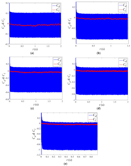
Figure 10.
Lift and drag coefficients of TWW cylinder under various wave amplitudes. (a) = 0.01. (b) = 0.02. (c) = 0.03. (d) = 0.04. (e) = 0.05.
Figure 11 shows the lift and drag coefficient characteristics under different wave amplitudes, including the mean and RMS values of lift and drag coefficients. Form Figure 11a, with the increase of , decreases slightly, which is smaller than the standard circular cylinder result. Overall, there is less difference in compared to that in standard cylinder. When amplitude ratio , dramatically decreases to 0.005 and reaches the minimum, which drops by 99.48% from that of standard circular cylinder. When increases from 0.02 to 0.05, shows a slightly increasing trend. equals to 0.012 at , which dropped by 98.7% from that of standard circular cylinder. In Figure 11b, with the increase of , decreases from −0.010 to −0.456, and increases from 0.085 to 0.385, which is almost 4.7 times the standard circular cylinder result. It’s easily observed that different wave amplitudes have little impact on and . However, and change obviously as increases from 0.01 to 0.05. To make TWW perform an ideal functionality in eliminating the aerodynamic forces, should be chosen, which can eliminate lift without extra significant drag oscillation.
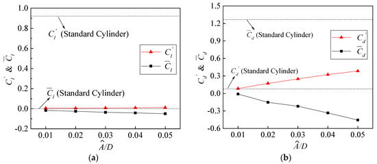
Figure 11.
Characteristic values of lift and drag coefficient under different wave amplitudes. (a) . (b) .
3.3. Influence of Different Wave Numbers
In this part of simulation, the wave number is, respectively, set as 3, 4, 5 and 6 in rear section of 1/4 cylinder. As TWW propagated downstream, the amplitude ratio equals to 0.02 and the velocity ratio equals to 2.0. The lift and drag coefficient time histories under different wave numbers are shown in Figure 12. The results indicate that the TWW with different wave numbers can suppress the cylinder wake. On the other hand, the mean and fluctuating lift coefficients keep almost unchanged with the increase in wave number. In the meantime, as wave number changes from 3 to 6, there is little change in fluctuating drag coefficient, while the mean drag coefficient decreases to negative values.
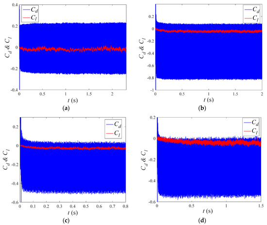
Figure 12.
Lift and drag coefficients under different wave numbers. (a) N = 3. (b) N = 4. (c) N = 5. (d) N = 6.
Figure 13 shows the characteristic values of lift and drag coefficient under different wave numbers, including the mean and RMS values of lift and drag coefficient. In Figure 13a, with the increase in N, decreases slightly from −0.019 to −0.039. almost hardly changes, whose values are between 0 and 0.01. It is observed that the fluctuating lift coefficient has been tremendously suppressed, however, different wave numbers have little impact on fluctuating lift coefficient after activating TWW, in comparison with the standard circular cylinder. Figure 13b shows that decreases to negative values and changes from 0.166 to 0.195 with the increase in N. It indicates that the cylinder′s reverse thrust increases gradually with the increase of N, and the wave number has some effect on .
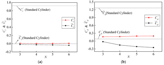
Figure 13.
Characteristic values of lift and drag coefficient under different wave numbers. (a) . (b) .
3.4. Influence of Different Wave Velocities
The “Downstream” propagation direction of TWW is selected to further study the effect of wave velocity. The wave number is set as 4, and the amplitude ratio is 0.02. Figure 14 shows the lift and drag coefficient time histories under given velocity ratios of 0.5, 1.0, 1.5, 2.0, 2.5, 3.0, 3.5, 4.0, 4.5, and 5.0. From the results of the lift coefficient fluctuation, the cylinder wake is suppressed in different degrees, but the fluctuation of lift coefficient increases slightly after . The mean lift coefficient decreases to negative values as increases. With the increase in wave velocity, the mean drag coefficient decreases dramatically but the fluctuating drag coefficient increases gradually, as shown in Figure 14.
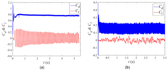
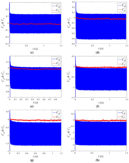
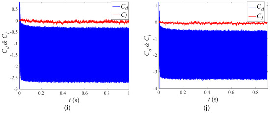
Figure 14.
Lift and drag coefficient under different wave velocities. (a) . (b) . (c) . (d) . (e) . (f) . (g) . (h) . (i) . (j) .
Figure 15 shows the characteristic value analysis of lift and drag coefficients under different wave velocities, including the mean and RMS values of lift and drag coefficients. In Figure 15a, with the increase of , changes from a result larger than that of standard circular cylinder to a result less than that of standard circular cylinder. As for the overall time, has little difference with that of standard circular cylinder in the range of the whole velocity ratios. As increases from 0.5 to 1.5, decreases dramatically from 0.115 to 0.003. In addition, reaches the minimum at , whose value decreases by 99.63% than that of standard circular cylinder. increases slightly from 0.005 to 0.036 as increases from 2.0 to 5.0. In addition, equals to 0.036 at , which achieves 96.09% reduction from the result of standard circular cylinder. In Figure 15b, with the increase of , decreases from 0.761 (60.04% of standard cylinder) to −1.8774, and increases from 0.014 to 1.037 (almost 12.8 times the result of standard circular cylinder). From the analysis results above, it is indicated that the velocity ratio is the optimal wave velocity for TWW flow control with respect to the control effect and energy input.
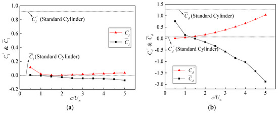
Figure 15.
Characteristic values of lift and drag coefficient under different wave velocities. (a) . (b) .
4. Conclusions
In the present research, the CFD numerical simulation was employed to investigate the oscillating wake of flow around a fixed cylinder with the traveling wave wall at a high Reynolds number. The influence factors of TWW flow control method were investigated, i.e., the TWW propagation direction, wave amplitude, wave number and wave velocity. The main conclusions are as follows.
The TWW with “Downstream” propagation direction can successfully eliminate the alternating shedding vortex behind the cylinder under the condition of , and of TWW cylinder decreases by 99.48% from that of standard circular cylinder. The TWW cylinder in “Upstream” propagation direction enhances the cylinder wake. Neither “Corotating-Clockwise” nor “Corotating-Counterclockwise” could eliminate the cylinder oscillating wake.
Wave amplitude should be taken as 0.02D to obtain the optimal control effect. At the wave amplitude ratio of 0.02, decreases dramatically to 0.005. When increases from 0.02 to 0.05, increases slightly, while dropped by 98.7% from the result of standard circular cylinder at . With the increase in , decreases from −0.010 to −0.456, and increases to almost 4.7 times the result of standard circular cylinder.
Wave number N has relatively slighter effect on lift and drag coefficients. The , and show little changes with the increase of wave number N. is less than 0, and the absolute value of increases as wave number N increases, which indicates that the reverse thrust applied to the cylinder increases gradually with the increase in wave number N.
The fluctuating lift coefficient reaches the minimum at , which drops by 99.63% from the result of standard cylinder. When , takes a slow increasing tendency and increases to 3.91% of the result of standard circular cylinder. With the increase of , decreases gradually and finally approaches to zero at . However, increases gradually with increasing and finally reaches to about 12.8 times the result of standard circular cylinder at . Considering the control effect and energy input under the Reynolds number in this study, is the optimal wave velocity for TWW flow control in this paper.
Author Contributions
Conceptualization, F.X.; investigation, F.X. and X.L.; writing—original draft preparation, F.X.; writing—review and editing, X.L. and W.B.; visualization, W.B. All authors have read and agreed to the published version of the manuscript.
Funding
This research was funded by the National Natural Sciences Foundation of China (NSFC) (52078175, 51778199 and U1709207), the Natural Science Foundation of Guangdong Province (2019A1515012205), the fundamental research funds of Shenzhen Science and Technology plan (JCYJ20190806144009332, JCYJ20180306172123896), and the Stability Support Program for colleges and universities in Shenzhen (GXWD20201230155427003-20200823134428001).
Institutional Review Board Statement
Not applicable.
Informed Consent Statement
Not applicable.
Data Availability Statement
Data are contained within this article.
Conflicts of Interest
The authors declare no conflict of interest.
References
- Laima, S.; Li, H.; Chen, W.-L.; Li, F. Investigation and control of vortex-induced vibration of twin box girders. J. Fluids Struct. 2013, 39, 205–221. [Google Scholar] [CrossRef]
- Chen, W.-L.; Zhang, Q.-Q.; Li, H.; Hui, H. An experimental investigation on vortex induced vibration of a flexible inclined cable under a shear flow. J. Fluids Struct. 2015, 54, 297–311. [Google Scholar] [CrossRef]
- Chen, W.-L.; Li, H.; Hu, H. An experimental study on the unsteady vortices and turbulent flow structures around twin-box-girder bridge deck models with different gap ratios. J. Wind Eng. Ind. Aerodyn. 2014, 132, 27–36. [Google Scholar] [CrossRef]
- Li, H.; Chen, W.-L.; Xu, F.; Li, F.-C.; Ou, J.-P. A numerical and experimental hybrid approach for the investigation of aerodynamic forces on stay cables suffering from rain-wind induced vibration. J. Fluids Struct. 2010, 26, 1195–1215. [Google Scholar] [CrossRef]
- Gao, D.-L.; Chen, W.-L.; Li, H.; Hu, H. Flow around a circular cylinder with slit. Exp. Therm. Fluid Sci. 2017, 82, 287–301. [Google Scholar] [CrossRef]
- Bearman, P.W.; Owen, J.C. Reduction of bluff-body drag and suppression of vortex shedding by the introduction of wavy separation lines. J. Fluids Struct. 1998, 12, 123–130. [Google Scholar] [CrossRef]
- Bechert, D.W.; Bruse, M.; Hage, W.; van der Hoeven, J.G.T.; Hoppe, G. Experiments on drag-reducing surfaces and their optimization with an adjustable geometry. J. Fluid Mech. 1997, 338, 59–87. [Google Scholar] [CrossRef]
- Choi, K.-S. Near-wall structure of a turbulent boundary layer with riblets. J. Fluid Mech. 1989, 208, 417–458. [Google Scholar] [CrossRef]
- Lee, S.-J.; Jang, Y.-G. Control of flow around a NACA 0012 airfoil with a micro-riblet film. J. Fluids Struct. 2005, 20, 659–672. [Google Scholar] [CrossRef]
- Owen, J.C.; Bearman, P.W.; Szewczyk, A.A. Passive control of VIV with drag reduction. J. Fluids Struct. 2001, 15, 597–605. [Google Scholar] [CrossRef]
- Choi, J.I.; Xu, C.X.; Sung, H.J. Drag reduction by spanwise wall oscillation in wall bounded turbulent flows. AIAA J. 2002, 40, 842–850. [Google Scholar] [CrossRef]
- Choi, K.-S.; Clayton, B.R. The mechanism of turbulent drag reduction with wall oscillation. Int. J. Heat Fluid Flow 2001, 22, 1–9. [Google Scholar] [CrossRef]
- Chen, W.-L.; Xin, D.-B.; Xu, F.; Li, H.; Ou, J.-P.; Hui, H. Suppression of vortex-induced vibration of a circular cylinder using suction-based flow control. J. Fluids Struct. 2013, 42, 25–39. [Google Scholar] [CrossRef]
- Chen, W.-L.; Li, H.; Hui, H. An experimental study on a suction flow control method to reduce the unsteadiness of the wind loads acting on a circular cylinder. Exp. Fluids 2014, 55, 1–20. [Google Scholar] [CrossRef]
- Chen, W.-L.; Cao, Y.; Li, H.; Hui, H. Numerical investigation of steady suction control of flow around a circular cylinder. J. Fluids Struct. 2015, 59, 22–36. [Google Scholar] [CrossRef]
- Chen, W.-L.; Gao, D.-L.; Yuan, W.-Y.; Li, H.; Hui, H. Passive jet control of flow around a circular cylinder. Exp. Fluids 2015, 56, 1–15. [Google Scholar] [CrossRef]
- Modi, V.J. Moving surface boundary-layer control: A review. J. Fluids Struct. 1997, 11, 627–663. [Google Scholar] [CrossRef]
- Kubo, Y.; Yukoku, E.; Modi, V.J.; Yamaguchi, E.; Kato, K.; Kawamura, S.-I. Control of flow separation from leading edge of a shallow rectangular cylinder through momentum injection. J. Wind Eng. Ind. Aerodyn. 1999, 83, 503–514. [Google Scholar] [CrossRef]
- Mittal, S. Control of flow past bluff bodies using rotating control cylinders. J. Fluids Struct. 2001, 15, 291–326. [Google Scholar] [CrossRef]
- Korkischko, I.; Meneghini, J.R. Suppression of vortex-induced vibration using moving surface boundary-layer control. J. Fluids Struct. 2012, 34, 259–270. [Google Scholar] [CrossRef]
- Yang, Z.; Wu, J.Z. Drag reduction by axisymmetric travelling wavy wall. J. Univ. Sci. Tech. 2005, 35, 471–479. [Google Scholar]
- Wu, C.J.; Xie, Y.Q.; Wu, J.Z. “Fluid Roller Bearing” effect and flow control. Acta Mech. Sin. 2003, 19, 476–484. [Google Scholar]
- Wu, C.-J.; Wang, L.; Wu, J.-Z. Suppression of the von Kármán vortex street behind a circular cylinder by a travelling wave generated by a flexible surface. J. Fluid Mech. 2007, 574, 365–391. [Google Scholar] [CrossRef]
- Xu, F.; Chen, W.-L.; Xiao, Y.-Q.; Li, H.; Ou, J.-P. Numerical study on the suppression of the vortex-induced vibration of an elastically mounted cylinder by a traveling wave wall. J. Fluids Struct. 2014, 44, 145–165. [Google Scholar] [CrossRef]
- Versteeg, H.K.; Malalasekera, W. An Introduction to Computational Fluid Dynamics: The Finite Volume Method; Wiley: New York, NY, USA, 1995. [Google Scholar]
- Wieselsberger, C. Neuere Feststellungen über die Gesetze des Flüssigkeits-und Luftwiderstands. Phys. Z. 1921, 22, 321–328. (In German) [Google Scholar]
- Munson, B.R.; Young, F.D.; Okiis, T.H. Fundamentals of Fluid Mechanics, 5th ed.; Wiley: New Delhi, India, 2002. [Google Scholar]
- Chen, W.L.; Wang, X.L.; Xu, F.; Li, H.; Hu, H. Passive jet flow control method for suppressing unsteady vortex shedding from a circular cylinder. J. Aerospace Eng. 2017, 30, 04016063. [Google Scholar] [CrossRef] [Green Version]
- Relf, E.F.; Simmons, E.F.G. The Frequency of Eddies Generated by the Motion of Circular Cylinders through a Fluid; Taylor & Francis: Abingdon, UK, 1924. [Google Scholar]
- Delany, N.K.; Sorensen, N.E. Low-Speed Drag of Cylinders of Various Shapes; Technical Note 303; National Advisory Committee for Aeronautics: Washington, DC, USA, 1953. [Google Scholar]
- Roshko, A. Experiments on the flow past a circular cylinder at very high Reynolds number. J. Fluid Mech. 1961, 10, 345–356. [Google Scholar] [CrossRef] [Green Version]
- Bearman, P.W. On vortex shedding from a circular cylinder in the critical Reynolds number régime. J. Fluid Mech. 1969, 37, 577–585. [Google Scholar] [CrossRef]
- Mustto, A.A.; Bodstein, G.C.R. Subgrid-Scale Modeling of Turbulent Flow Around Circular Cylinder by Mesh-Free Vortex Method. Eng. Appl. Comput. Fluid Mech. 2011, 5, 259–275. [Google Scholar] [CrossRef] [Green Version]
- Labbé, D.F.L.; Wilson, P.A. A numerical investigation of the effects of the spanwise length on the 3-D wake of a circular cylinder. J. Fluids Struct. 2007, 23, 1168–1188. [Google Scholar] [CrossRef]
- Al-Jamal, H.; Dalton, C. Vortex induced vibrations using Large Eddy Simulation at a moderate Reynolds number. J. Fluids Struct. 2004, 19, 73–92. [Google Scholar] [CrossRef]
- Fan, J.J.; Tang, Y.G.; Zhang, R.Y. Numerical simulation of viscous flow around circular cylinder at high Reynolds numbers and forced oscillating at large ratio of amplitude. J. Hydrodyn. 2012, 27, 24–32. [Google Scholar]
Publisher’s Note: MDPI stays neutral with regard to jurisdictional claims in published maps and institutional affiliations. |
© 2022 by the authors. Licensee MDPI, Basel, Switzerland. This article is an open access article distributed under the terms and conditions of the Creative Commons Attribution (CC BY) license (https://creativecommons.org/licenses/by/4.0/).