Article

A Gravity-Compensated Upper-Limb Exoskeleton for Functional Rehabilitation of the Shoulder Complex

1
Rehab Technologies Lab, Istituto Italiano di Tecnologia, 16163 Genova, Italy
2
INAIL Centro di Riabilitazione Motoria, 56048 Volterra, Italy
*
Author to whom correspondence should be addressed.
Appl. Sci. 2022, 12(7), 3364; https://doi.org/10.3390/app12073364
Submission received: 9 February 2022 / Revised: 18 March 2022 / Accepted: 24 March 2022 / Published: 25 March 2022

Abstract

:
In the last decade, several exoskeletons for shoulder rehabilitation have been presented in the literature. Most of these devices focus on the shoulder complex and limit the normal mobility of the rest of the body, forcing the patient into a fixed standing or sitting position. Nevertheless, this severely limits the range of activities that can potentially be simulated during the rehabilitation, preventing the execution of occupational therapy which involves the execution of tasks based on activities of daily living (ADLs). These tasks involve different muscular groups and whole-body movements, such as, e.g., picking up objects from the ground. To enable whole-body functional rehabilitation, the challenge is to shift the paradigm of robotic rehabilitation towards machines that can enable wide workspaces and high mobility. In this perspective, here we present Float: an upper-limb exoskeleton designed to promote and accelerate the motor and functional recovery of the shoulder joint complex following post-traumatic or post-surgical injuries. Indeed, Float allows the patient to move freely in a very large workspace. The key component that enables this is a passive polyarticulated arm which supports the total exoskeleton weight and allows the patient to move freely in space, empowering rehabilitation through a deeper interaction with the surrounding environment. A characterization of the reachable workspace of both the exoskeleton and the polyarticulated passive arm is presented. These results support the conclusion that a patient wearing Float can perform a wide variety of ADLs without bearing its weight.

1. Introduction

Shoulder injuries are among the most common occupational hazards: fractures, dislocations, rotator cuff tears and other soft-tissue injuries often require surgeries and several months of rehabilitation therapy. At the same time, loss of function at shoulder level leads to significant impairment in daily life activity due to the crucial role of the shoulder complex in allowing for hand movements in the workspace.
Moreover, the shoulder complex has the greatest mobility of all joints in the human body [1] thanks to an intricated set of muscles, tendons, ligaments, bones and joints [2] working in a coordinated and synchronous way to offer a constant compromise between mobility and stability and, consequently, this poses real challenges when it comes to rehabilitation [3].
In this perspective, robotic rehabilitation can be a valid tool to provide a more repeatable and measurable therapy compared to conventional therapies. In fact, in the last decade, several exoskeletons for shoulder rehabilitation have been presented in the literature [4,5,6,7,8,9]. Most of these devices focus on the shoulder complex and limit the normal mobility of the rest of the body, forcing the patient into a fixed standing or sitting position.
Indeed, most of the exoskeletons presented so far were designed for neurologic patients and thus a fixed position may be useful especially in subjects with severe impairment or in the early rehabilitation phases.
Conversely, engagement in occupational activities is usually introduced later in the patient’s care pathway. Nevertheless, this classical rehabilitation approach severely limits the range of activities that can potentially be simulated during the first rehabilitation phases. Indeed, several activities of daily living (ADLs) involve different muscular groups and whole-body movements; from relocating or moving objects in the space, to sideways reaching or picking objects from the ground. It has been proven that psychologically rewarding exercises, as those included in occupational therapy, improve the patient’s motivation [10]. Furthermore, the capability of full body motion to engage people has already been demonstrated in fields such as digital gaming [11,12], highlighting the potential benefits deriving from physical–social interactions as well.
To enable a careful whole-body functional rehabilitation [13], the challenge is to shift the paradigm of robotic rehabilitation towards machines that can enable wide workspaces and high mobility in ecologically valid scenarios [14]. In this perspective, here we present Float: an upper-limb exoskeleton designed to promote and accelerate the motor and functional recovery of the shoulder joint complex following post-traumatic or post-surgical injuries. The key component is a passive polyarticulated arm which supports the total exoskeleton weight and allows the patient to move freely in space. Float empowers rehabilitation through a deeper interaction with the surrounding environment compared to other rehabilitation exoskeletons presented in literature [4,5,6,7,8,9].

2. Materials & Methods

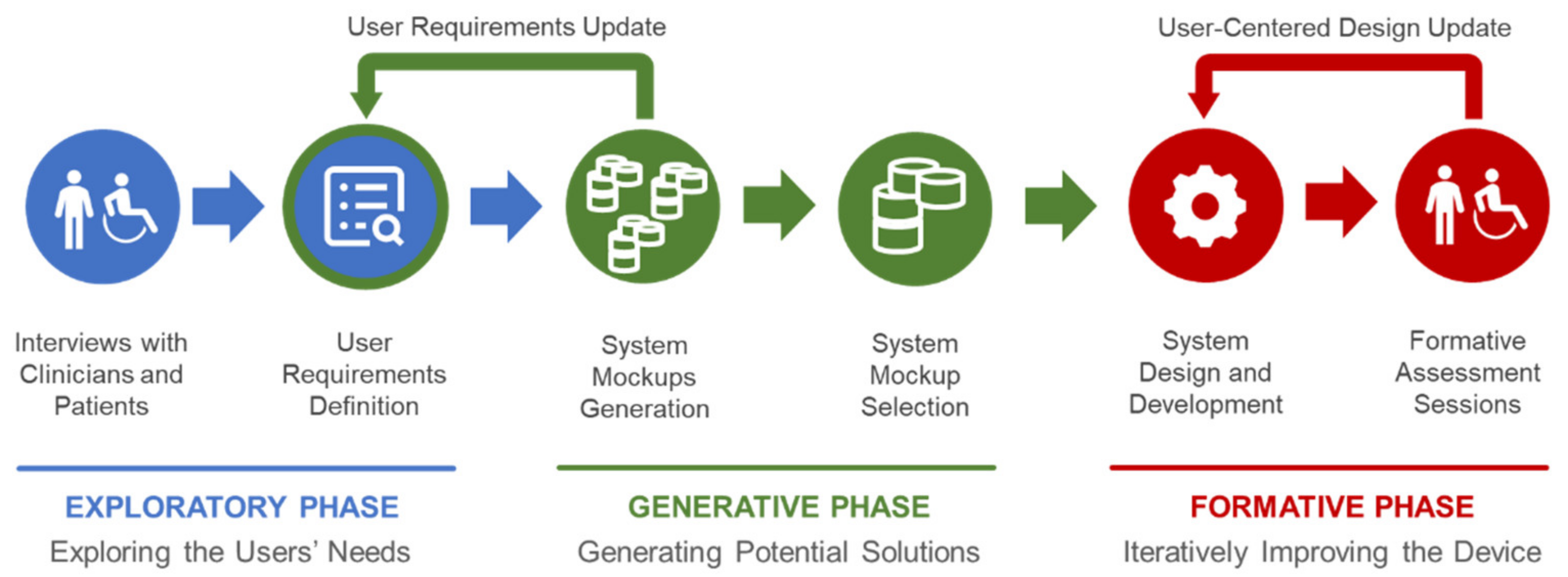
2.1. Float System Co-Design Approach

The current version of Float derives from a user-centered design process (Figure 1) that extends the steps presented in [15] in order to provide the developers with different implementation options that directly derive from a co-design approach, involving clinicians, technicians and patients along three phases. The goal established by the clinicians was to provide an ecologically valid device to simulate real-life tasks and work-related activities within clinical centers. Indeed, the device was created to be used in the clinic, under the supervision of a therapist and not at home or at work.
The initial discussions with the clinicians focused on requirements that could have been satisfied by a list of macroscopically different systems, not necessarily leading to an exoskeleton or an end-effector. A series of interviews during the “exploratory phase” enabled an initial understanding of the user needs, considering as users both the clinicians and the patients according to the rehabilitative goals. The main result of this phase is constituted by 3 user requirements that became design principles of Float:
  • Wide freedom of movement of the patient during rehabilitation;
  • Possibility of rehabilitation while sitting, standing and bent over;
  • Weight of the exoskeleton not perceived by the patient.
The principles 1 and 2 (which depends on 1 too) were posed by the clinicians for easing the future exploitation of Float in occupational therapy with ecologically valid settings and tasks. On the other hand, principle 3 was generally requested by the patients too (always with the goal of making the technology supportive yet, as much as possible, “transparent” in the user experience). Accordingly, the designers and the developers generated—“generative phase”—a set of mockups of the device. These solutions were evaluated by technicians and clinicians in order to match the three principles listed above alongside general requirements of effectiveness, comfort and safety in order to select the basic configuration of the device. This phase was especially useful for clarifying the opportunity of creating a hybrid configuration of exoskeleton (the wearable component) and end-effector (the polyarticulated arm) that offer major advantages of both robotic systems in rehabilitation procedures. Finally, the first prototype of Float was implemented and the “formative phase”—based on the CEI EN 62366:2015 standards for usability engineering (Medical devices—Part 1: Application of usability engineering to medical devices)—started as an iterative and participatory design and evaluation process conducted to progressively refine the device through user tests.
Such a process involved both hardware and software components of Float. A series of usability tests involved 2 physiatrists and 5 physiotherapists (at the INAIL Motor Rehabilitation Center—Crm—of Volterra, Italy). Several tests were conducted, including the usability of the graphic user interface (GUI), the control, mechanical features and interfaces with the patients. Usability methods were exploited for understanding how the users interact with the devices: the participants were invited to describe the steps of their reasoning while creating a user ID and a sequence of exercises (thinking aloud technique).
Patients’ safety during Float utilization was our top priority. Therefore, we applied a risk management process, appropriate technical standards and regulations during the generative (considering the mockups) and formative phases (assessing the prototypes).
In particular, we identified, estimated, evaluated and mitigated all risks connected with the device’s use according to CEI EN 14971:2019 (Medical devices—Application of risk management to medical devices). During mechanical and electrical development of the device, we were compliant with the requirements contained in IEC EN 60601-1:2006/A11:2011/A1:2013 (Medical electrical equipment: Part 1: general requirements for safety and essential performance) and IEC EN 60601-1-2:2015 (Medical electrical equipment—Part 1–2: General requirements for safety—Collateral standard: Electromagnetic compatibility), gaining certifications for both the mentioned technical norms. Software development followed the requirements of CEI EN 62304:2006 (Medical device software—Software life-cycle processes).

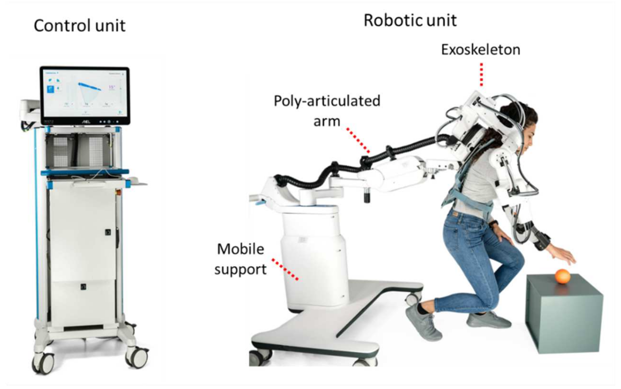
2.2. Float System Description

The Float system includes two functional units: a robotic unit and a control unit (Figure 2).

2.2.1. Robotic Unit

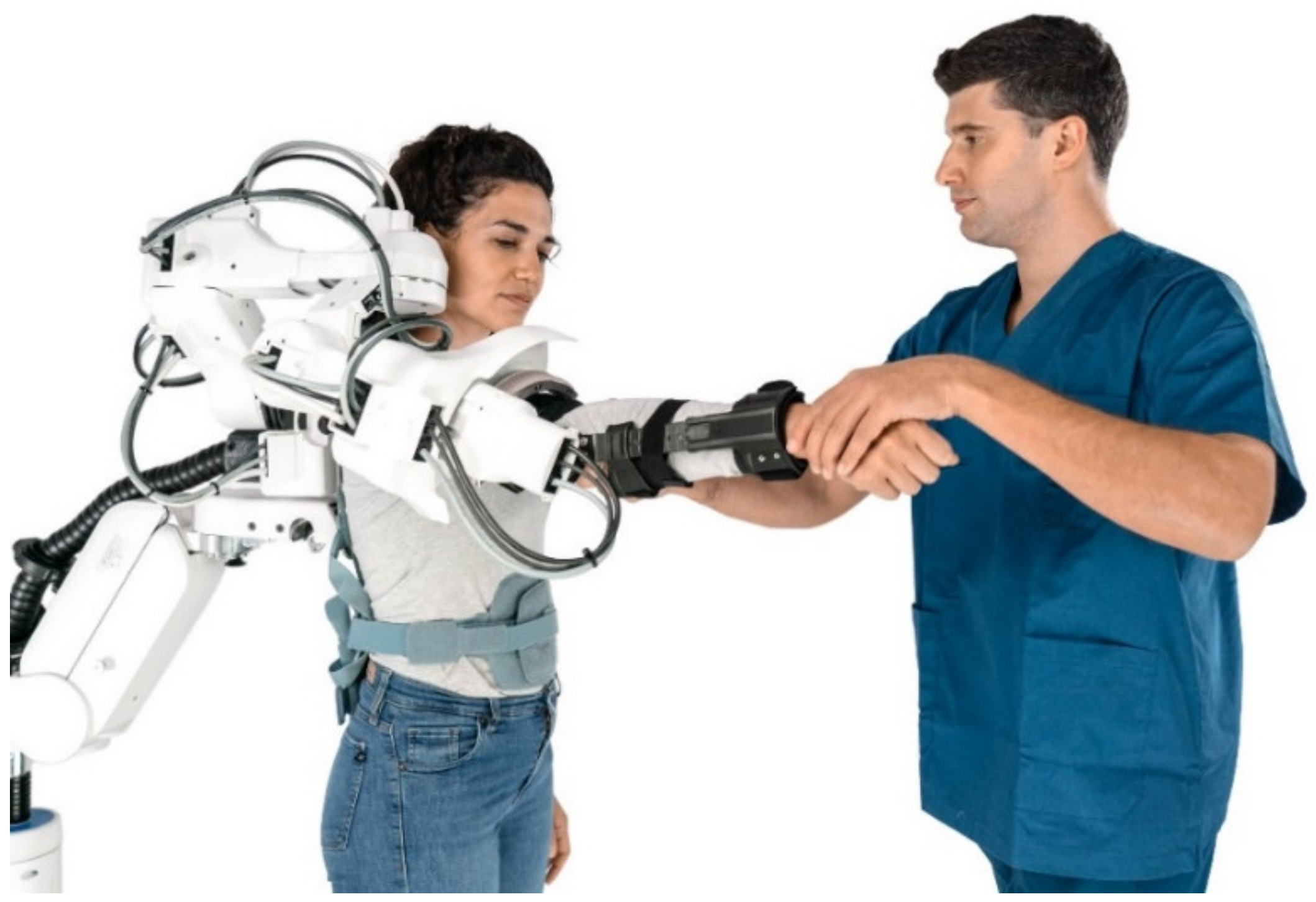
The robotic unit is in direct contact with the patient. It includes three elements: the actuated exoskeleton, a passive and polyarticulated arm and a mobile support with a telescopic column.
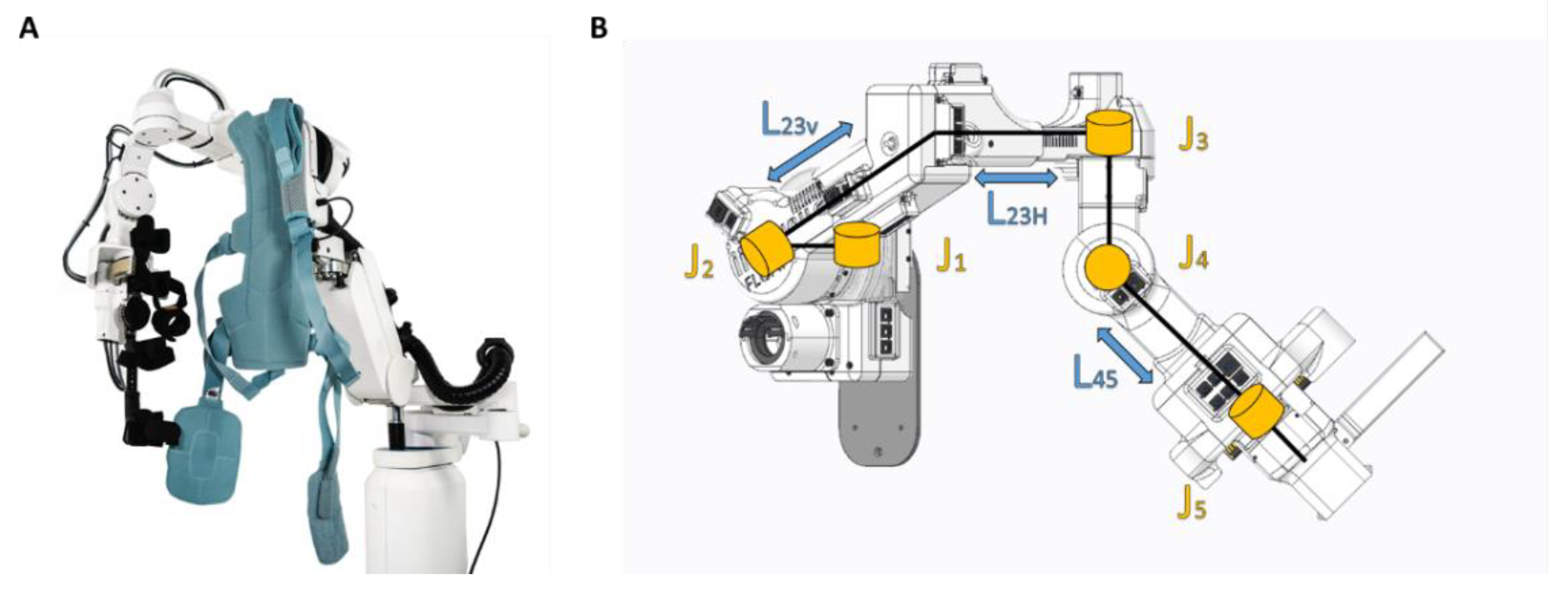
The exoskeleton is the active part of the system and allows all the movements of the shoulder complex of the patient (according to design principle 1 about the arm). Two interfaces connect the patient to the exoskeleton: an orthopaedic bust and an arm brace. The orthopaedic bust (Spinalplus, RO + TEN s.r.l., Milano, Italy) holds the patient to the base of the exoskeleton in a semi-rigid and repeatable manner. It also allows a shoulder strap to be removed if needed, which may be the case for patients with pain-sensitive shoulders. The second interface is an arm brace (Elbo 2.0, RO + TEN s.r.l., Milano, Italy) which connects the patient arm and forearm with the exoskeleton end-effector. This interface allows the transmission of movement from the exoskeleton to the patient in an ergonomic way (Figure 3).
The Float exoskeleton is made of five rotational joints, with each degree of freedom representing a movement of the shoulder complex (Figure 3). The first two joints (J1 and J2) provide the two main movements of the shoulder girdle. The first joint allows the scapula protraction/retraction. The second joint allows the scapula elevation/depression. The last three joints represent the glenohumeral movements: horizontal abduction/adduction, flexion/extension, internal and external rotation. They are assembled in a Euler spherical wrist configuration, also known as “ZYZ”. This configuration, with respect to the Roll-Pitch-Yaw spherical configuration adopted in different rehabilitation exoskeletons, e.g., Harmony [9] and ANYexo [5], guarantees a better understanding of the contribution of each revolute joint rotation to the glenohumeral motion. Regarding J2, J3 and J4, the axis of rotation of the joint matches with the axis of rotation of the motor. They include a brushless DC motor equipped with integrated incremental encoder and a triplet of Hall sensors, and a Harmonic Drive gear unit. The output angular position is detected by a 20-bit magnetic encoder. Regarding J1 and J5, the axis of rotation of the joint does not match with that of the motor. For the first joint, a leverage system transmits the rotation from the motor to the output, while for the last joint the mechanism was made through two gear wheels. For J1 and J5, the joint position is sensed by means of a precision potentiometer (Table 1).
The five degrees of freedom of the exoskeleton are sufficient to move the upper arm of the patient in the Cartesian space, guaranteeing the possibility to perform most of the activities of daily living (ADLs).
Each motor is driven by means of a dedicated driver module, which manages the signals from the available sensors (fast shaft encoder, Hall sensors, joint angle sensor) and provides the needed power signals to the motor. Motor control is realized as a standard six-step drive, in which a pulse-width-modulated (PWM) voltage signal is sequentially applied to two of the three phase terminals of the motor stator, in order to generate a suitably rotating magnetic field. The duty cycle of the driving voltage signal can be controlled in order to modulate the driving voltage mean value. In the implemented low-level control scheme, said duty cycle value is computed in real-time by the algorithm for position control and friction compensation, which will be discussed in the following.
Motor drive modules communicate with each other and the main control unit over a CAN bus line.
The exoskeleton is easily adaptable to individuals with different anthropometric characteristics ranging from the 5th percentile female and the 95th percentile male [16]. Such anthropometric features can be reached thanks to the continuous adjustability in length of the main connection parts (hereinafter the “link”) between the motor modules (Figure 3). Among the exoskeleton rigid links, L23 and L45 were designed to include adjustable passive prismatic joints to regulate the overall size of the exoskeleton. This was carried out to accommodate the different anthropometries. Specifically, L23 contains two different adjustable passive prismatic joints called L23v and L23h ranging, respectively, between 174   mm < L 23 v < 224   mm and 208   mm < L 23 h < 263   mm . L45 instead ranges between 250   mm < L 45 < 300   mm .
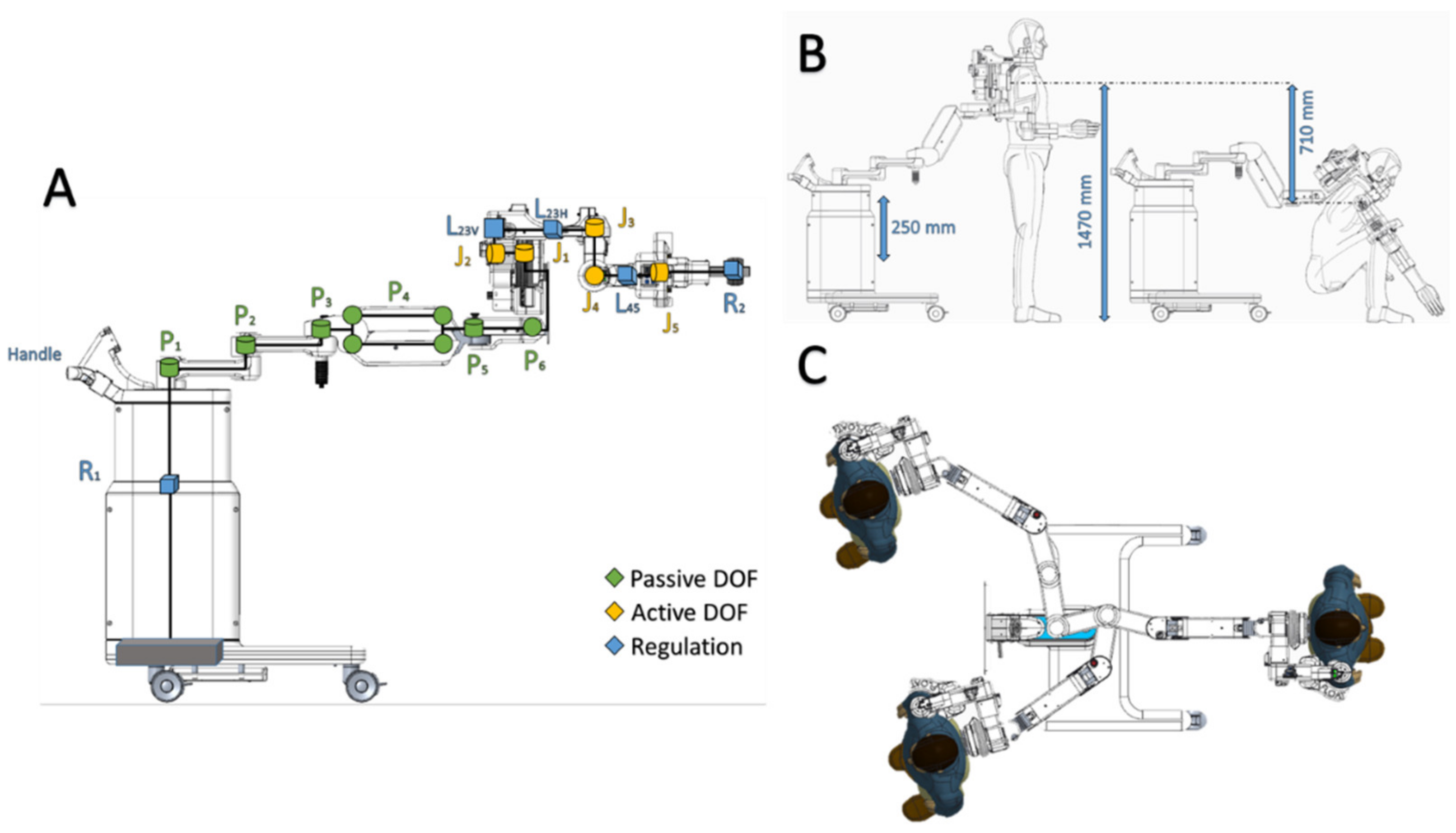
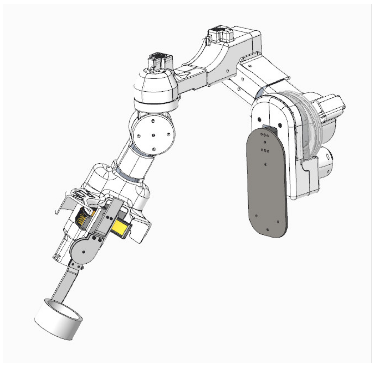
The passive polyarticulated arm is constituted by 6 degrees of freedom (P1–P6), as observable in Figure 4. Joints 1, 2, 3, 5 and 6 are simple rotational joints (hinges), while joint 4 (P4) is a four-bar linkage mechanism. The decision to adopt a four-bar linkage for this joint allows the introduction of a tunable parallel spring used to compensate gravitational load of the polyarticulated arm and exoskeleton (according to design principle 3).
The exoskeleton and the polyarticulated arm are connected to a mobile base with four wheels through a telescopic column (R1) which allows one to adjust the height of the exoskeleton by acting on the handle on its top (Figure 4) to accommodate the different anthropometries. Connected to the base, an emergency disconnect switch allows one to turn off all the motors in case of any issue.
Depending on the rehabilitation needs, it is possible to keep the polyarticulated arm locked in a specific position. For instance, this allows the patient to perform the passive mobilization therapy in a sitting or standing position. Conversely, if the arm is unlocked, the patient can freely explore a much larger workspace which is crucial for occupational therapy and ADL [17] (according to design principles 1 and 2).
The overall resulting robot has been modelled using the modified Denavit–Hartenberg (mDH) convention. This choice comes from the fact that the mDH defines the axis of rotation zi with respect to the i-th joint, thus guaranteeing a better comprehension of the kinematic model to non-expert users. The adopted mDH convention is based on the following homogeneous transformation matrix:
T i i 1 = cos θ i sin θ i cos α i 1 sin θ i sin α i 1 0   sin θ i cos θ i cos α i 1 cos θ i sin ( α i 1 ) 0   0 sin α i 1 cos α i 1 0   a i 1 d i sin α i 1 d i cos α i 1 1  
The resulting mDH parameters are presented in Table 2.
The angles θ i represent the degrees of freedom of the exoskeleton and are characterized by the range of motion (ROM) showed in Table 3. These are bounded by mechanical stops in order to avoid collisions and ensure the user safety.
The same convention has been used to model the passive polyarticulated arm. The resulting mDH parameters are summarized in Table 4. It is important to notice that an artificial degree of freedom angle THETA4′ has been defined to consider the presence of the four-bar linkage. The definition of such angle simplifies the modelling of the robot, in fact it avoids the definition of all the joints of the four-bar linkage. However, it is required to set THETA4′ = THETA4 for each configuration to guarantee a correct operation of the robotic model.
Similarly, to the exoskeleton, the angles THETAi represent the degrees of freedom of the polyarticulated arm and are characterized by the range of motion (ROM) shown in Table 5. These are bounded by mechanical stops in order to avoid collisions and ensure the user safety.

2.2.2. Control Unit

The control unit allows the physical therapist to set all the parameters and design a new exercise. The therapist can easily start and stop the movement execution while monitoring all the active joints.
An articulated monitor stand allows a practical orientation of a 21′ medical panel (PC OR-PC21, ACL, Markkleeberg, Germany) with a range of motion of 180°. The medical keyboard (K2-MED, ProKeys, Zschorlau, Germany) and mouse (M5-WT, ProKeys, Zschorlau, Germany) are on a retractable shelf.
An electrical cabinet placed below the screen contains the main control unit and the electrical system. On the right side of the box, an emergency disconnect switch allows one to turn off all the motors if needed. The entire control unit is on four wheels for ease of transport.
The control board is a custom-made multifunctional device, its main duties are: data processing, power supply management and sequencing, fault detection and management, supply current monitoring and the robot data routing. The board contains a System-on-Chip module (Trenz TE0720-03-1CF), based on Xilinx Zynq-7000 SoC, which integrates a dual-core ARM Cortex-A9 CPU and an Artix-7 FPGA. The CPU section is in charge for running the operating system, as well as all the processing tasks. The FPGA section implements all the hardware peripherals for interfacing with both onboard and external functional modules. The System-on-Chip module interacts with several mixed-signal and power stages which implement all the functionalities of the control unit.
The electrical system is in charge for providing all the power rails to the system, and for guaranteeing the needed level of electrical safety. Furthermore, it is based on the following main elements: a medical isolation transformer (Reomed 600, Reo, Solingen, Germany), a medical modular power supply (CoolX600, Advanced Energy, Denver, CO, USA) and a custom electrical panel.

2.3. Software and Control

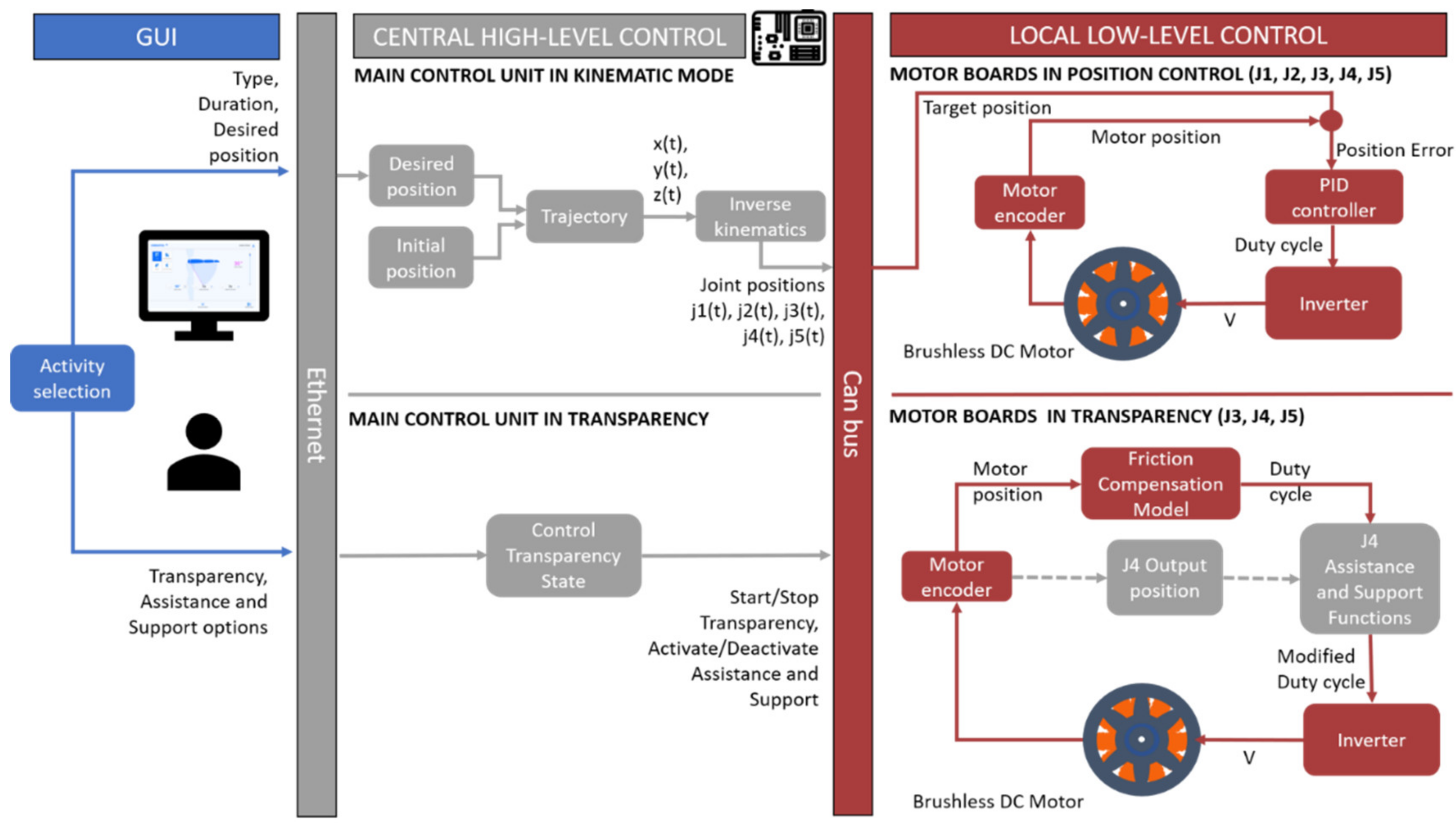
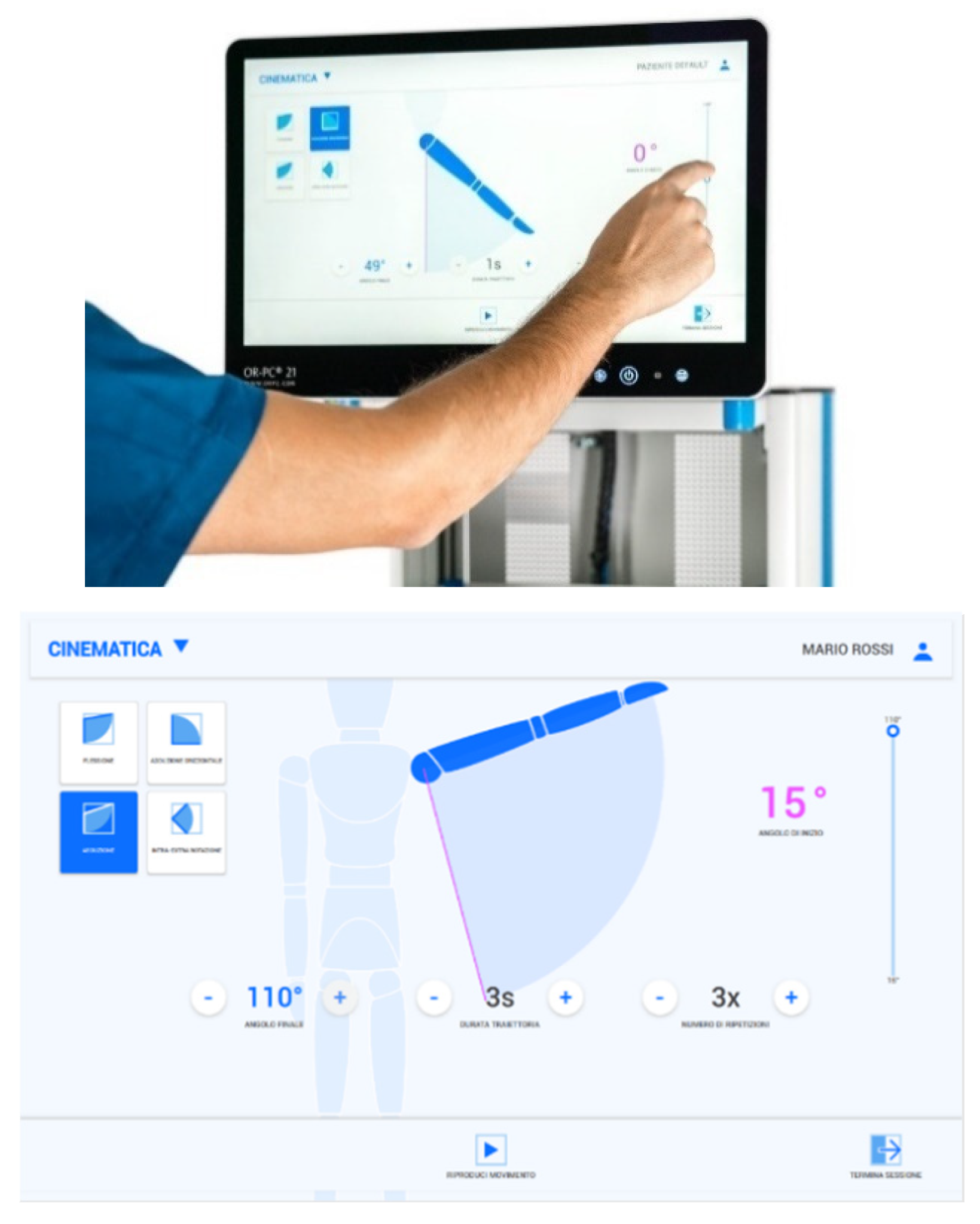
Float is controlled by an interactive GUI, which allows the therapist to supervise the session and perform the rehabilitation protocol. The GUI is loaded on a touch-screen panel PC that communicates with the main control unit through Ethernet. At the central high level, the control unit receives all commands and coordinates the activity of the motor boards in order to implement all the control modalities. It is responsible for handling the communication with the GUI and the boards, implementing computation to define motor trajectories and monitoring the system performance to ensure safety. The main control unit communicates with the five boards through CAN protocol.
The Float system can perform in three modalities: Kinematic, Transparency Mode and Repeat Trajectory.
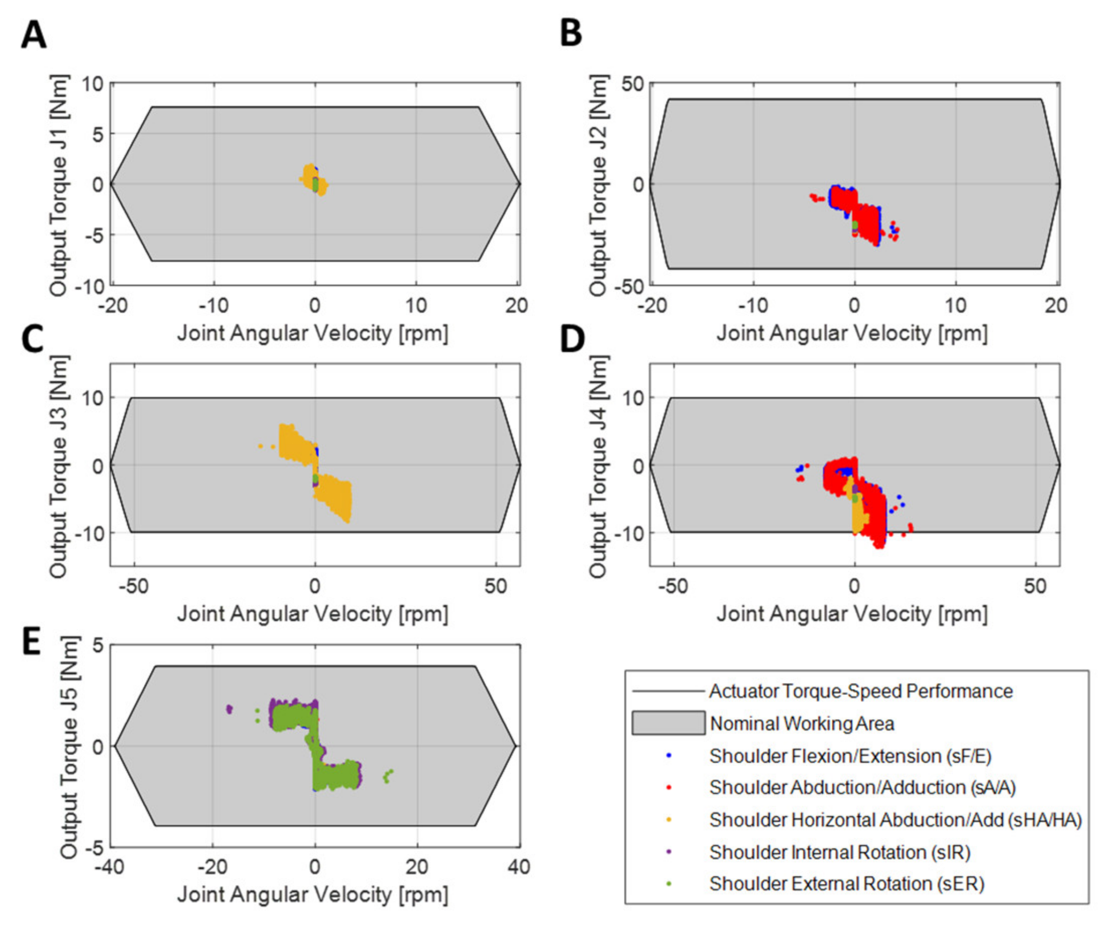
At local level, the 5 motor boards implement position control (Figure 5), used in Kinematic mode and Repeat Trajectory mode, where the boards receive the next desired position and provide the right amount of voltage to each motor. In Transparency mode, the local control is responsible for compensating the friction torques by calculating the motor torque as a function of dynamic variables as described below.
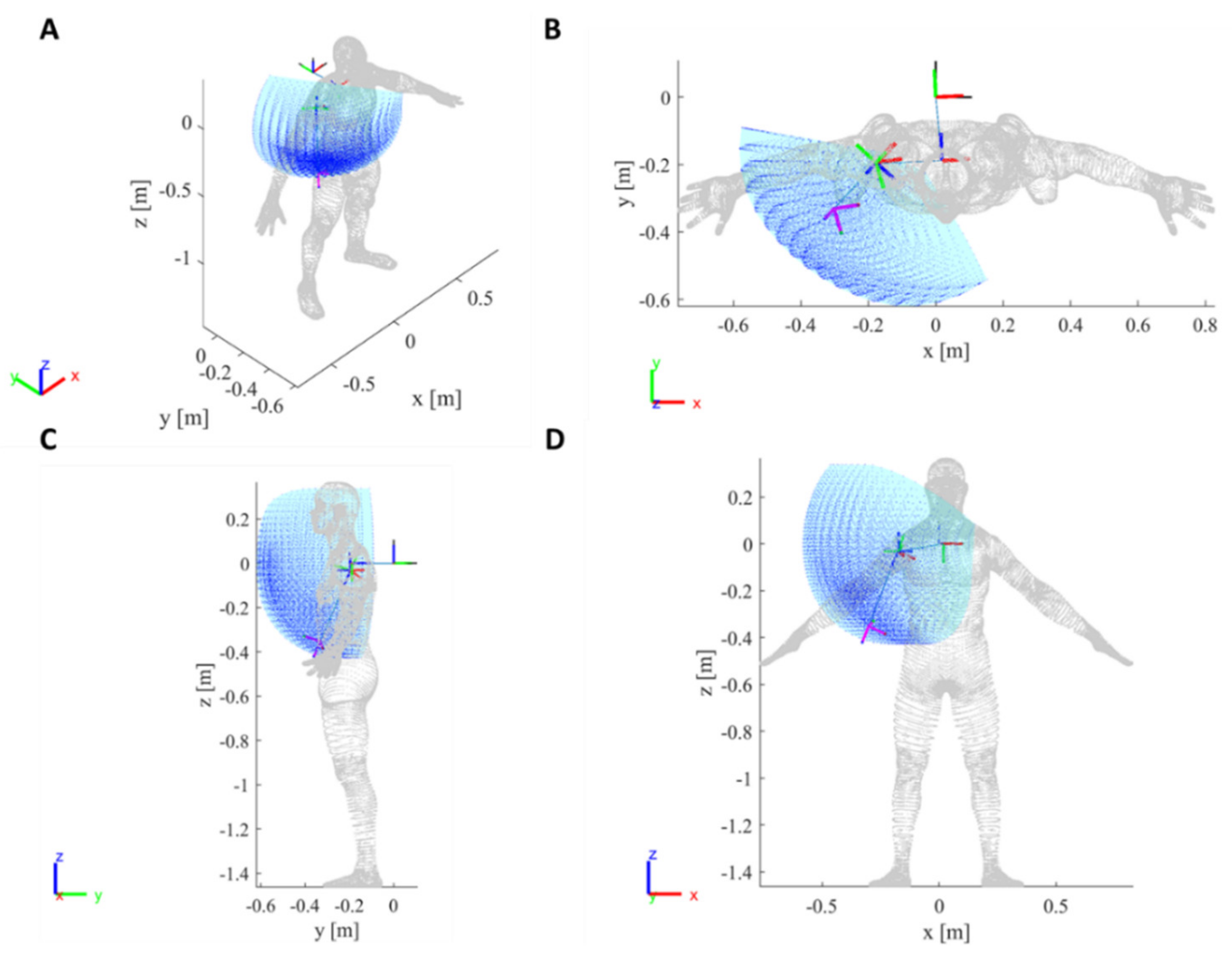
In Kinematic mode, the patient is passive, and the exoskeleton moves the upper limb to operator-selected positions by performing an elementary movement in a fixed amount of time. Such modality helps the patient in doing repetitive, simple tasks, often crucial in rehabilitation.
Maximum speed allowed for safety reasons is 45 deg/s. The user can choose between 4 exercises: shoulder flexion/extension (sF/E), shoulder abduction/adduction (sA/A), shoulder horizontal abduction/adduction (sHA/HA) and shoulder internal external rotation (sIER) (Figure 6).
The exercises can be repeated multiple times and can be saved to be performed in sequences during Repeat Trajectory mode. The Range of Motion (ROM) of the exoskeleton with respect to these exercises is shown in Table 6.
The first three movement types performed in Kinematic mode include a synergy between the humerus and the scapula defined as the scapulohumeral rhythm.
The scapulohumeral rhythm is the kinematic interaction between the humerus and the scapula. In the early phase of abduction (0°–30°), motion occurs primarily at the glenohumeral (GH) joint. For instance, an abduction of 180° would be accomplished through approximately 120° of the glenohumeral joint motion and 60° of the scapula-thoracic (ST) joint motion, thus with a ratio of 2:1.
To reproduce movements which respect this interaction, J1 and J2 were set to reproduce ST motion and J3, J4 and J5 to reproduce GH joint motion.
During sA/A, the center of the GH joint translates in the human coronal plane (J4), and this movement results from a harmonized motion of depression/elevation caused by the ST joint (J2).
During sHA/HA, the center of GH joint moves in the transverse plane (J3), producing shoulder protraction/retraction by the ST joint (J1).
The interactions described are simulated by the exoskeleton by introducing coupling functions between J1/J3 and J2/J4. The movements of the first two joints are functions of the desired horizontal abduction and abduction, respectively, thus depending on J3 and J4:
θ j 1 = f θ j 3 ,   j 1 c o u p l i n g
θ j 2 = f θ j 4 ,   j 2 c o u p l i n g
where θ j i represents the angular position of joint Ji, for i = 1 ,   ,   4 , while j 1 c o u p l i n g defines the coupling level between J1 and J3 and its value is 9, whereas j 2 c o u p l i n g defines the relation between J2 and J4 and its value is 4. The corresponding functions can be defined as shown below:
θ j 1 = θ j 3 j 1 c o u p l i n g
θ j 2 = 0 i f   θ j 4 < t h r e s h o l d θ j 4 j 2 c o u p l i n g i f   θ j 4 > t h r e s h o l d  
The coupling between J2 and J4 is applied exclusively after the elevation in the coronal plane raises over the threshold value of 30°, thus making J4 work alone in the early phases of abduction to better emulate the physiological movement.
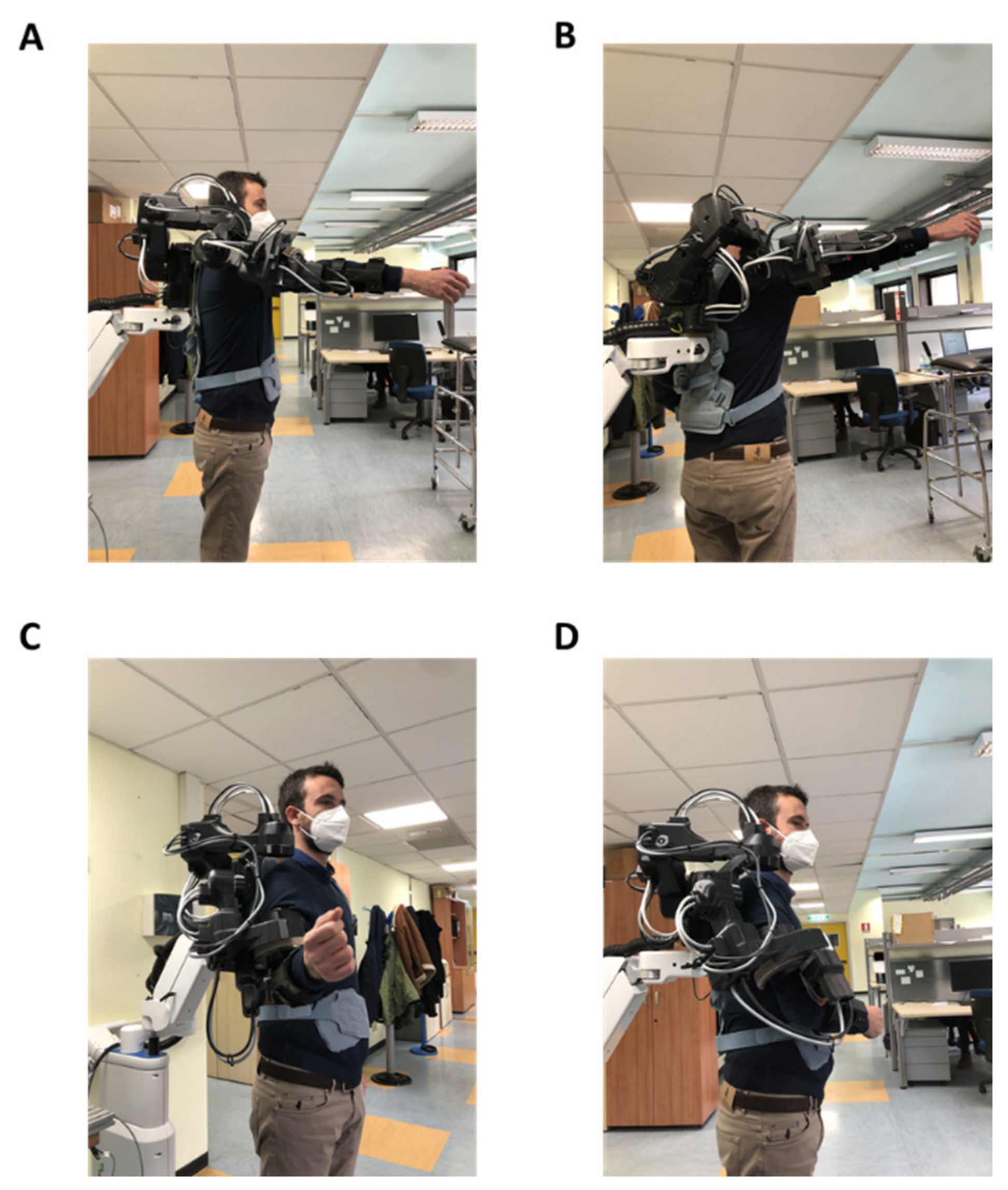
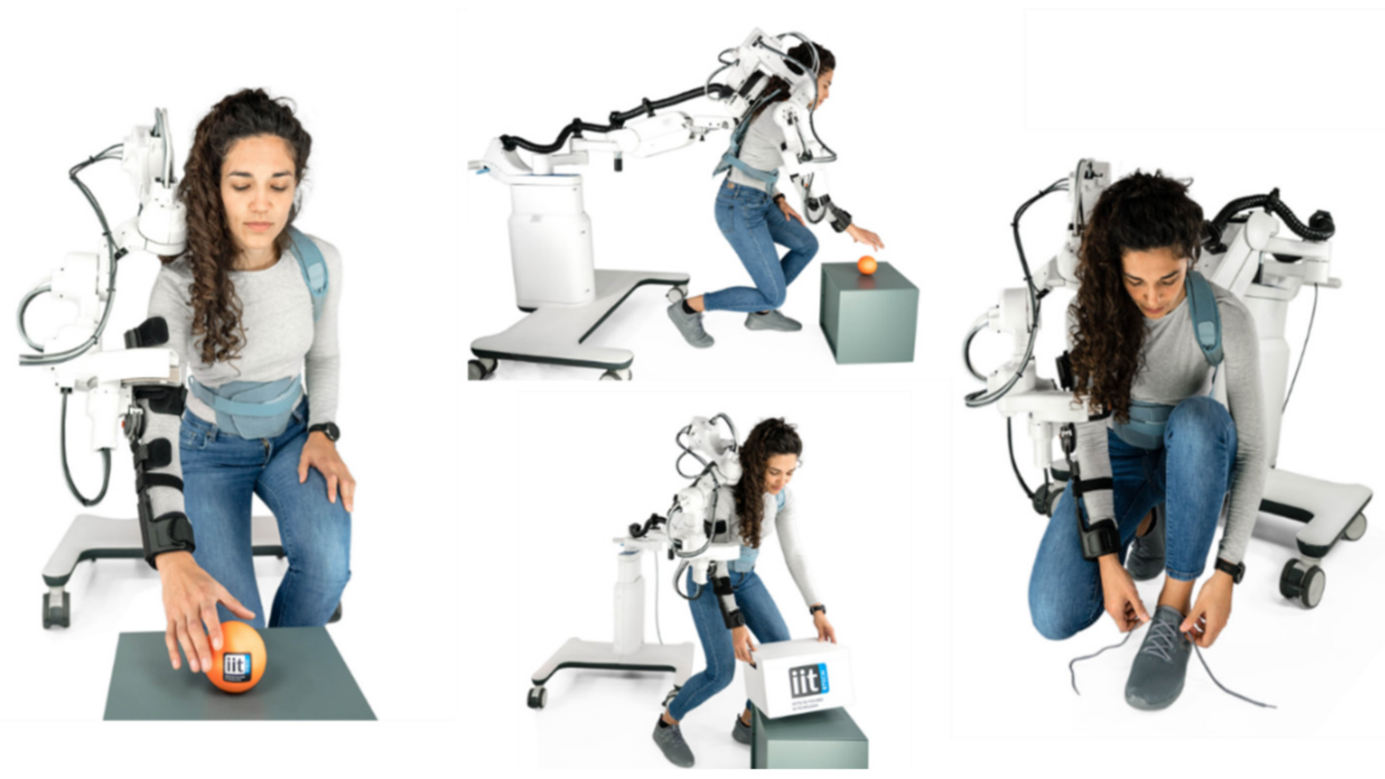
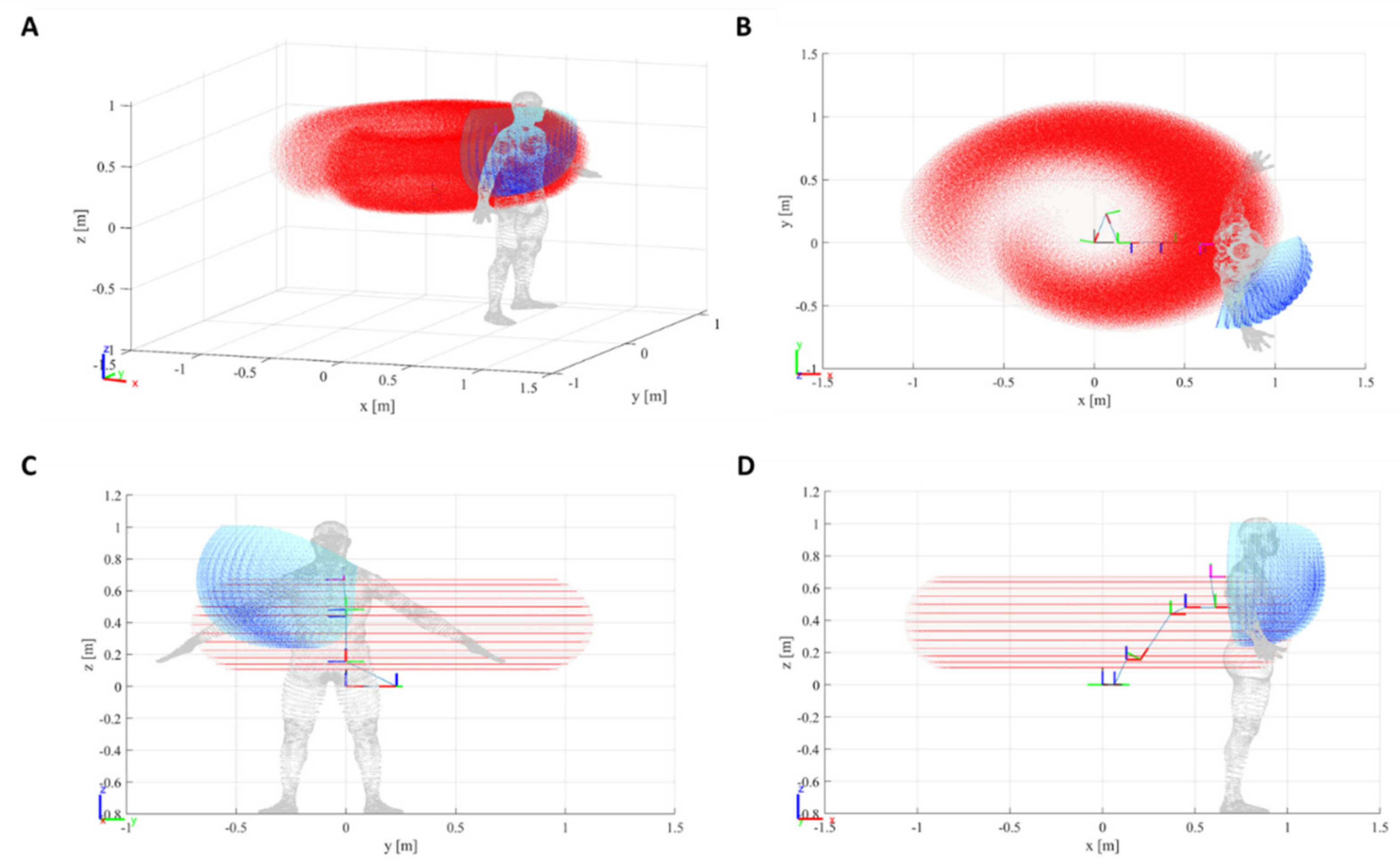
In Transparency mode the patient is active and can freely move the limb (and thus the exoskeleton) without feeling resistance thanks to a friction compensation at the joints. This function enables the patient to perform exercises by interacting with daily life objects (Figure 7).
During transparency, it is possible to activate the additional features Assistance and Support.
Assistance helps the patient in performing upwards vertical motions by applying an extra push which depends on J4 current angle. Support provides a viscous resistance in downwards vertical motions, in order to support the weight of the arm and avoid rapid descending movements. These modalities intervene on joint 4 and their intensity can be selected between three values: low, medium and high. Empirical values for these levels were chosen over the average weight of a human arm.
Transparency mode is also activated to record an arbitrary trajectory under the guidance of the therapist. In this operational mode, the therapist freely moves the patient’s limb following the desired trajectory, which is recorded by the device in terms of motor positions and can be subsequently replicated (Repeat Trajectory mode).
Transparency is here intended as compensation of friction torques at each single joint, by means of a suitably applied motor torque as a function of the dynamic variables.
In Float device, transparency is achieved by means of a model-based feed-forward compensation of friction at each of the involved joints, which is described below. Despite being sub-optimal, this technique proved very well suited for the application. Inertial effects are intrinsically minimized in the application, as the movements performed during therapy are designed to be slow and continuous in order to minimize accelerations and avoid patient discomfort.
The equation of motion referred to the output (slow) shaft of the single joint gearmotor can be written as follows:
τ e x t + τ f + τ m o t = J ω ·
where:
  • τ e x t is the external torque acting on the joint output shaft, due to contact interaction with the rest of the system via downstream connecting link, and to inertial forces due to accelerated motion of the joint base.
  • τ f is the total friction torque in motor and gearbox, output shaft referred.
  • τ m o t is the electromagnetic torque exerted on motor rotor by motor stator, multiplied by gearbox gear ratio.
  • J is the total moment of inertia of motor rotor plus gearbox, output shaft referred.
  • ω · is the angular velocity of the output shaft.
The motor torque term τ m o t can be expressed (using Kirchhoff’s law and disregarding inductive effects as negligible in the bandwidth of interest) as a linear function of motor excitation voltage V m o t and angular velocity ω , by expressing motor torque in terms of motor current, and motor back-emf in terms of angular velocity.
Regarding modeling of friction terms, the dynamic case ( ω 0 ) is first considered. The static case and associated static friction treatment will be then addressed.
For non-null velocity, friction torque as a function of angular velocity is modeled as a sum of a Coulomb zeroth-order term, plus a viscous linear term, plus a second-degree additional term.
Within the previously stated assumptions, the gearmotor equation of motion can be thus rewritten as follows:
τ e x t a ω b + c ω 2 ω ω + dV m o t = J ω ·
where friction torque is represented by the second and third terms. The experimental values of the ratios a / d , b / d , c / d are obtained by best fit during a joint characterization phase, in which a suitable set of values for excitation voltage V m o t are applied to the motor, under zero external torque, and resulting asymptotic output shaft angular velocity values are recorded.
Using the estimated model parameters, transparency is then obtained by dynamically linking the motor voltage to the measured velocity, in order to compensate the friction torque terms.
Motor voltage is generated by the inverter stage, by means of standard pwm modulation of the inverter supply voltage, with carrier wave frequency (20 kHz) outside audible range, and duty cycle parameter D 1 ,   1 dynamically computed as follows:
D = g 1 V supply 1 d a ω + b + c ω 2 ω ω
where V supply is the measured value of the inverter stage supply voltage; negative duty cycle values are associated with motor voltage polarity reversal.
Here, an overall strictly positive gain parameter g is introduced to perform a fine tuning of the compensation degree in order to address the effects of variation of the external parameters affecting the behavior of the joint (as temperature and applied load). However, we empirically discovered that the aforementioned variations in the environment conditions produced a minimal variation in the joint response and did not substantially affect Transparency mode performance. At null velocity, in static friction regime, the above compensation scheme cannot be used. Instead, a low-frequency sine wave voltage is applied to the motor, such that the resulting peak motor torque is slightly less than the experimentally determined static friction maximum value. This allows for a quasi-compensation of static torque at least around the peak of the sine wave, so that the full static friction is only perceived by the patient (when exerting force on the robot) within less than one cycle period, before dynamic conditions are established, thus minimizing motion startup effort.
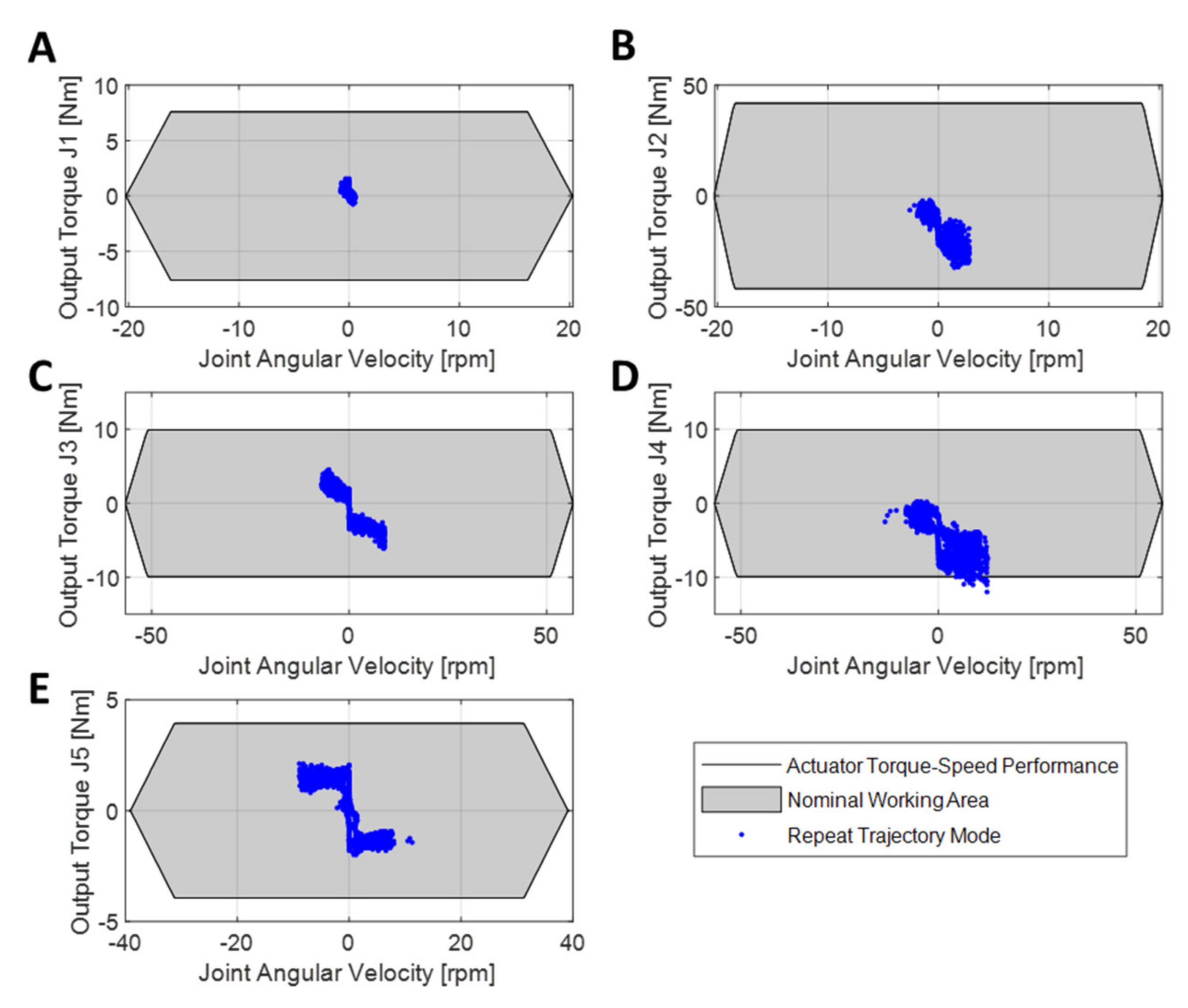
In the Repeat Trajectory mode, the patient is passive as in the Kinematic mode, but the trajectories can be more complex. It reproduces previously saved trajectories recorded either in Kinematic and Transparency modes and allows their combination in sequences, interposing or not temporal pauses of varying duration between one and the other (Figure 8). This is crucial to increase the variability and thus the engagement of the patient during the rehabilitation session. It also enables the therapist to add non-elementary movements to the rehabilitation protocol.
The exercises executed in the Kinematic and Transparency modes are sampled at 20 Hz and saved as a collection of temporally equidistant via points.
The recording may carry imperfections due to the human/robot interaction, resulting in jerky movements during the trajectory repetition that might be uncomfortable for the patient. For this reason, the recorded set of samples is smoothed through a moving-average algorithm and the trajectory is determined by minimum jerk interpolator. This approach minimizes jerkiness due to manipulation imperfections, improving patient comfort.
Float is controlled by means of a graphical user interface (GUI) connected to the device. The GUI enables the therapist to create new personalized profiles for each patient and to navigate through the different functionalities (Figure 9).
The Patient Profile contains few essential personal data (name, surname, birth date) and technical information that enable the exoskeleton to perform in the limit of the user’s range of motion, setting the maximum and minimum angles (deg) for the sF/E, sA/A, sHA/HA, sIER.

3. Results

In this section the authors present the main results related to the developed device. Specifically, in Section 3.1, a characterization of the reachable workspace of both the exoskeleton and the polyarticulated passive arm is presented. The reachable workspace is represented by the cloud point of all possible configurations given the range of motion of each joint of the device.
In Section 3.2, the authors report the results of the actuation characterization. Such characterization has been performed to assess, in a worst-case scenario, the capability of the exoskeleton actuators to perform the most relevant rehabilitative exercises. The tests were carried out loading the device with an external load mimicking the weight of a 99th percentile human arm.

3.1. Workspace Characterization

The resulting robot rigid body tree, based on the mDH, has been modelled exploiting the Matlab® Robotics Toolbox library and is presented in Figure 10.
The obtained robot rigid body tree, combined with the available ROM of each joint, was used to evaluate the cloud point of reachable Cartesian configuration.
The cloud point (Figure 10) includes an area close to the patient’s body in which collisions might occur. The extension of this region depends on the patient’s anthropometric measurements. This area was defined as a cone region through mechanical and software constraints and is universal to all patient profiles. The robot never performs inside it in the Kinematic mode.
As a consequence of the robot’s layout, there is a kinematic singularity in the z plane, when joints J3 and J5 are vertically aligned. This singularity is inside the non-accessible cone region and it is never reached in the Kinematic mode.
The resting position of the robot (Figure 11) is the configuration the robot assumes when it is in the Kinematic mode but is not performing exercises. It was defined to avoid patient discomfort, fit to most anthropometrical measures and avoid the collision zone.
θ r e s t = θ j 1 = 5 ° θ j 2 = 0 ° θ j 3 = 45 ° θ j 4 = 30 °   θ j 5 = 35 °
The same approach has been carried out to generate the polyarticulated arm cloud point, depicted in red in Figure 12.
The maximum volume of operation offered by the passive polyarticulated arm has been estimated computing the convex hull of the passive arm cloud point (see red cloud point of Figure 12). Its value is equal to 1.53   m 3 . It is important to notice that the cloud point of the passive arm has a non-perfect convex shape, as observable from Figure 12; thus, the convex hull volume computation is necessarily an overestimation. Nonetheless, this overestimation is negligible for the purposes of the computation, since the interest of the calculation is to offer a qualitative upper bound to the maximum operational volume of the passive arm itself.
The same volume computation operation has been performed also for the actuated exoskeleton offering as a result a volume of 0.12   m 3 . In this case, the actuated exoskeleton cloud point is convex, and the convex hull volume estimation can be considered in a more quantitative way.

3.2. Actuation Characterization

In order to characterize and validate the actuation system performances, we performed a series of test campaigns involving the most relevant upper-limb motions in a worst-case scenario.
The exoskeleton was configured in the maximum percentile condition (95th percentile male), namely extending all the adjustable links to their maximum positions. This represents the worst working operation condition for the actuation system, since all the actuators will perceive the maximum gravitational load.
On top of this, we also added a load of 3.3 kg in correspondence to the arm brace. This weight corresponds to the 60% of a 99th percentile male human arm weight (5.56 kg [16]). The choice of 60% comes from a preliminary experimental analysis of the distribution of the human arm weight between the subject and the exoskeleton.
This additional load brings the test setup to the aforementioned worst-case scenario, namely the largest percentile patient (maximum gravitational load on the exoskeleton) with the exoskeleton carrying the highest possible load.
In such a condition, the following exercises—in the Kinematic mode—have been performed:
  • Shoulder flex-extension 60° in 2 s (full-extended arm);
  • Shoulder abduction 95° in 3 s (full-extended arm);
  • Horizontal shoulder abduction 100° in 3 s (full-extended arm);
  • Humerus internal rotation 55° in 2 s (elbow at 90°);
  • Humerus external rotation 50° in 2 s (elbow at 90°).
All the exercises were performed at the maximum allowed speed. This does not represent the maximum reachable speed of the exoskeleton, but it represents the allowed speed during clinical utilization of the device.
An additional test campaign was performed in the Repeat Trajectory mode, where the exoskeleton was first manually moved by an external user mimicking a complex motion involving all the five active joints of the device.
For each test, the angular positions and the absorbed motor currents were measured for each joint. From the angular positions, by means of numerical derivation, the angular speed of the joints was computed. Additionally, form the motor currents, using a model-based relationship, the generated output torques were estimated using the following relationship:
T j = i j K t j τ j η m j η t r j
where T j represents the j-th output torque, i j is the j-th joint motor current, K t j is the j-th motor torque gain, τ j is the j-th transmission ratio, η m j is the j-th motor efficiency and η t r j is the j-th transmission efficiency.
The experimental torque-speed profiles of the different performed exercises were then compared with the nominal torque-speed envelope of the gearmotor at each joint. The obtained results are presented in Figure 13 and Figure 14.
Figure 13 shows the cloud points of all the different Kinematic mode exercises. It can be observed that all the performed exercises cloud points lay within the nominal torque-speed envelope at each join. The only exception is observable on joint 4, where the shoulder abduction slightly overshoots the nominal torque. However, this does not represent a critical condition for the system, since the nominal torque can be exceeded for a limited period of time.
Additional observations can be made with respect to the specific exercises. In fact, shoulder abduction and flexion, mainly involve J2 and J4, while horizontal abduction activates mostly J1, J3, and J4. The internal and external rotation are carried out mainly by J5.
Another consideration can be made on J1, where it seems that the actuation system for that joint has been oversized. Nonetheless, this does not consider the fact the exoskeleton was tested in vertical configuration, where J1 perceives a negligible external torque. A different situation will appear if the back support of the exoskeleton arm would have been tilted (passive joint P6, Figure 4), producing in this way a much larger gravitational contribution on the J1 load.
At last, a final comment is related to J2 and J4. These two joints present a torque-speed profile not centered with respect to the torque zero axis. This is due to the fact that they carry most of the gravitational load of the exoskeleton arm. This does not represent an immediate issue for the exoskeleton, since all the tested exercises are supported by the exoskeleton actuators. However, in future developments, it would be reasonable to evaluate possible passive gravity compensation solutions, e.g., springs, to cancel this torque offset and reduce the working load on the actuators.
Figure 14 presents the cloud points of the Repeat Trajectory mode exercise. Additionally, in this case, it can be noticed that the performed task falls within the actuator nominal performances (with the same consideration aforementioned on J4).
This demonstrates that the selected joint actuators were correctly sized for the exoskeleton’s most relevant tasks in a worst-case scenario condition.

4. Discussion and Conclusions

In this work we presented Float, a novel shoulder exoskeleton designed for the rehabilitation of orthopedic patients. We employed a user-centered design process based on an exploratory phase, a generative phase and a formative phase. The first phase was mainly constituted by interviews to understand all explicit and implicit needs of all the stakeholders involved (mainly patients and therapists). Following this process, during the generative phase, different mockups of Float have been designed, implemented and evaluated by the stakeholders to overcome the limitations of devices currently on the market. In particular, the main limitation of most of the other upper-limb exoskeletons is their reduced workspace, which forces the patient to perform exercises exclusively in a fixed sitting or standing position. This severely limits the range of activities that can potentially be simulated during the rehabilitation. Moreover, visual feedback is usually provided to the patient through a screen placed in front of the machine.
However, according to the occupational therapy perspective, simulating purposeful occupations such as daily life tasks or work activities is crucial to support a successful reintegration of the patients in their previous occupations and social roles [18,19,20].
Moreover, it has been demonstrated that prolonged functional deprivation gradually leads to maladaptive neuroplasticity changes, inducing in turn a persistent cycle of decreased use [21,22,23]. Conversely, the early introduction of a graded task-oriented motor training contributes to preserve motor programs and motivates the patient to actively participate in therapy, preventing the decline of motor performance caused by limb disuse.
Occupation-as-means is therapeutic when the activity has a purpose or goal that makes a challenging demand yet has an expectation of success, especially if using physical objects in an ecologically valid environment (i.e., similar to the real context).
Robotics-supported training is receiving growing attention in clinical rehabilitation, particularly in the neurological field. Nevertheless, robotic training is rarely reported as treatment after traumatic shoulder injuries; the few clinical trials conducted to date include robot-assisted exergames consisting of virtual object manipulation in a virtual environment [24].
The development of the Float shoulder exoskeleton is the result of an occupation-focused approach: we indeed hypothesize that an early habilitation to perform specific tasks using common objects in the real physical space can facilitate a more rapid recovery of the quality and effectiveness of upper-limb movements. The innovative mechanical solution to release the device from a fixed position allows the user to receive assistance in complex functional activities, fully integrating the upper limb in the whole-body movements.
Float opens up the possibility of carrying out occupational therapy in a large workspace thanks to the polyarticulated arm as detailed in the Results section. This innovation makes it possible to unlock a large number of exercises in the most natural way possible, i.e., without placing the weight of the exoskeleton on the patient.
Regarding the control, the implemented friction compensation represents a preliminary solution to guarantee a transparent behavior of the exoskeleton system. The solution proved to be effective and offered a sufficiently transparent behavior when operated by a healthy subject. Nonetheless, it is important to underline that more advanced and complete friction compensation techniques, especially for what concerns the strong non-linearity of harmonic drives, might be implemented to obtain an even better transparency behavior [25].
A final consideration must be made regarding the lack of a general gravity compensation of the exoskeleton weight. This has not been directly addressed for two reasons. The first one is the presence of the polyarticulated arm, that thanks to a parallel spring in joint 4 (P4) of the passive arm sustains most of the weight of the exoskeleton. The second factor is more related to control aspects. In fact, when the robot operates in the Kinematic mode, the need for force compensations is not required, since the robot is controlled in position. When instead the robot operates in the assistive mode, additional contributions—in terms of injected current to joint 4—are added when moving against gravity (Assistance and Support) as depicted in Figure 5.
Most of the state-of-the-art upper-limb exoskeletons, presented so far, focus on the shoulder complex and limit the normal mobility of the rest of the body, forcing the patient into a fixed standing or sitting position [5,6,9]. In terms of structure, the active part of the Float exoskeleton weighs 10.0 kg. However, it is difficult to compare with other devices due to the different number of active DOFs: e.g., ANYexo [5] has six DOF and weighs 12.98 kg, Harmony [9] has seven DOFs per arm and weighs 15.65 kg. Despite these differences, it is possible to compare the exoskeletons density per degree of freedom—namely the ratio between exoskeleton weight and number of DoFs. We observe in this way that the Float exoskeleton presents a density of 2 kg/DoF while ANYexo has 2.16 kg/DoF and Harmony 2.24 kg/DoF. This demonstrates how Float, even if marginally and qualitatively, represents a lighter solution for the rehabilitation of the upper limb. For what concerns the power capabilities of the device, Float has a total nominal power of 300 W (computed as the sum of the power of all the actuated joints) which leads to a power-to-weight ratio of 30 W/kg. In literature this information is not always available, the authors found data regarding the ARMin V and ANYexo devices, which show, respectively, a power-to-weight ratio of 24.7 W/kg and 18.5 W/kg. This highlights a slightly better performance of the Float exoskeleton also in terms of power density, further supporting the lightweight and power efficiency of the developed solution
Moreover, Float provides a physiological ROM for the entire shoulder complex with a safe design, compliant with the main requirements for medical devices.
We invested time and effort to build a system that can be safely used in clinical practice. This is a consistent paradigm shift when compared to classical research exoskeletons.
Compared to other approaches using compliant technologies (e.g., series elastic actuators) [5], we employed a classical approach (without torque sensing). Nevertheless, our approach guarantees robustness and the control strategies implemented in Float cover most of the needs for orthopedic patients. A clinical pilot trial is currently underway to perform a user-centered evaluation of Float, on orthopedic patients at the INAIL Motor Rehabilitation Center (Crm) of Volterra, Italy.
Additionally, the user-centered design and the development of a new version of Float is also adopting the principles of the International Classification of Functioning, Disability and Health (ICF) to further approach the user needs [17,26,27] within the exploratory and the generative phases. ICF is enabling a categorization of the needs of patients with shoulders pathologies that can be extended to the ecologically valid design of rehabilitative tasks that must be allowed by the new machine.

Author Contributions

S.B., F.T., L.D.G., G.C., C.P., A.B., S.S., A.S., G.B., I.C. and E.T. wrote the manuscript. S.B., F.T., G.C. and A.B. prepared the original figures. F.F. designed the original version and kinematics of the exoskeleton. F.T. performed the analyses. L.D.G., G.C. and P.R. designed and assembled the mechanical part of the systems. C.P., A.B. and S.M. wrote the software. F.V.S. and A.S. designed the electronics. S.B., F.F., M.L. and L.D.M. conceived the study. M.L. and L.D.M. acquired funding to conduct the research and revised the manuscript. All authors have read and agreed to the published version of the manuscript.

Funding

This research received funding by the Istituto Nazionale per l’Assicurazione contro gli Infortuni sul Lavoro (INAIL), under grant “Completamento dello sviluppo e della sperimentazione clinica di dispositivi robotici per la riabilitazione di tutti i principali distretti del corpo”.

Informed Consent Statement

Not applicable.

Data Availability Statement

The datasets generated and/or analyzed for this study are available from the corresponding author on reasonable request.

Acknowledgments

The authors would like to thank the Electronic Design Laboratory (IIT) for the design and development of the main control unit. Moreover, the authors would like to thank all the former colleagues at Rehab Technologies for their work on the first versions of the device.

Conflicts of Interest

The authors declare no conflict of interest.

References

  1. Halder, A.M.; Itoi, E.; Ana, K.-N. Anatomy and biomechanics of the shoulder. Orthop. Clin. 2000, 31, 159–176. [Google Scholar] [CrossRef]
  2. Engín, A. On the biomechanics of the shoulder complex. J. Biomech. 1980, 13, 575–590. [Google Scholar] [CrossRef]
  3. Veeger, H.E.J.; Van Der Helm, F.C.T. Shoulder Function: The perfect compromise between mobility and stability. J. Biomech. 2007, 40, 2119–2129. [Google Scholar] [CrossRef] [PubMed]
  4. Nef, T.; Guidali, M.; Riener, R. ARMin III–arm therapy exoskeleton with an ergonomic shoulder actuation. Appl. Bionics Biomech. 2009, 6, 127–142. [Google Scholar] [CrossRef] [Green Version]
  5. Zimmermann, Y.D.; Forino, A.; Riener, R.; Hutter, M. ANYexo: A Versatile and Dynamic Upper-Limb Rehabilitation Robot. IEEE Robot. Autom. Lett. 2019, 4, 3649–3656. [Google Scholar] [CrossRef] [Green Version]
  6. Trigili, E.; Crea, S.; Moise, M.; Baldoni, A.; Cempini, M.; Ercolini, G.; Marconi, D.; Posteraro, F.; Carrozza, M.C.; Vitiello, N. Design and Experimental Characterization of a Shoulder-Elbow Exoskeleton with Compliant Joints for Post-Stroke Rehabilitation. IEEE/ASME Trans. Mechatron. 2019, 24, 1485–1496. [Google Scholar] [CrossRef]
  7. Perry, J.C.; Rosen, J.; Burns, S. Upper-Limb Powered Exoskeleton Design. IEEE/ASME Trans. Mechatron. 2007, 12, 408–417. [Google Scholar] [CrossRef]
  8. Stroppa, F.; Loconsole, C.; Marcheschi, S.; Frisoli, A. A Robot-Assisted Neuro-Rehabilitation System for Post-Stroke Patients’ Motor Skill Evaluation with ALEx Exoskeleton. In Biosystems & Biorobotics; Springer Science and Business Media LLC: Berlin/Heidelberg, Germany, 2017; pp. 501–505. [Google Scholar]
  9. Kim, B.; Deshpande, A.D. An upper-body rehabilitation exoskeleton Harmony with an anatomical shoulder mechanism: Design, modeling, control, and performance evaluation. Int. J. Robot. Res. 2017, 36, 414–435. [Google Scholar] [CrossRef]
  10. Ikiugu, M.N.; Hoyme, A.K.; Mueller, B.A.; Reinke, R.R. Meaningful occupation clarified: Thoughts about the relationship between meaningful and psychologically rewarding occupations. S. Afr. J. Occup. Ther. 2015, 45, 47–50. [Google Scholar] [CrossRef]
  11. Bianchi-Berthouze, N.; Kim, W.W.; Patel, D. Does Body Movement Engage You More in Digital Game Play? and Why? In Proceedings of the Frontiers of Algorithmics; Springer Science and Business Media LLC: Berlin/Heidelberg, Germany, 2007; pp. 102–113. [Google Scholar]
  12. Bianchi-Berthouze, N. Understanding the role of body movement in player engagement. Hum. Comput. Interact. 2013, 28, 40–75. [Google Scholar]
  13. Byrne, D.P.; Ridgeway, E.M. Considering the Whole Body in Treatment of the Hemiplegic Upper Extremity. Top. Stroke. Rehabil. 1998, 4, 14–34. [Google Scholar] [CrossRef]
  14. Iwamoto, Y.; Imura, T.; Suzukawa, T.; Fukuyama, H.; Ishii, T.; Taki, S.; Imada, N.; Shibukawa, M.; Inagawa, T.; Araki, H.; et al. Combination of exoskeletal upper limb robot and occupational therapy improve activities of daily living function in acute stroke patients. J. Stroke Cerebrovasc. Dis. 2019, 28, 2018–2025. [Google Scholar] [CrossRef] [PubMed]
  15. Laffranchi, M.; D’Angella, S.; Vassallo, C.; Piezzo, C.; Canepa, M.; De Giuseppe, S.; Di Salvo, M.; Succi, A.; Cappa, S.; Cerruti, G.; et al. User-Centered Design and Development of the Modular TWIN Lower Limb Exoskeleton. Front. Neurorobotics 2021, 15, 15. [Google Scholar] [CrossRef] [PubMed]
  16. Tilley, A.R. The Measure of Man and Woman: Human Factors in Design; John Wiley & Sons: Hoboken, NJ, USA, 2001. [Google Scholar]
  17. Sivan, M.; Gallagher, J.; Holt, R.; Weightman, A.; Levesley, M.; Bhakta, B.; Holt, R. Investigating the International Classification of Functioning, Disability, and Health (ICF) Framework to Capture User Needs in the Concept Stage of Rehabilitation Technology Development. Assist. Technol. 2014, 26, 164–173. [Google Scholar] [CrossRef]
  18. Radomski, M.V.; Latham, C.A.T. Occupational Therapy for Physical Dysfunction; Lippincott Williams & Wilkins: Philadelphia, PA, USA, 2018. [Google Scholar]
  19. Fisher, A.G. Occupation-centred, occupation-based, occupation-focused: Same, same or different? Scand. J. Occup. Ther. 2013, 20, 162–173, Erratum in Scand. J. Occup. Ther. 2014, 21, 96–107. [Google Scholar] [CrossRef]
  20. Nielsen, K.T.; la Cour, K.; Christensen, J.R.; Pilegaard, M.S.; von Bülow, C.; Brandt, Åse; Peoples, H.; Jonsson, H.; Wæhrens, E.E. Lessons learned about occupation-focused and occupation-based interventions: A synthesis using group concept mapping methodology. Scand. J. Occup. Ther. 2020, 27, 481–492. [Google Scholar] [CrossRef]
  21. Huber, R.; Ghilardi, M.F.; Massimini, M.; Ferrarelli, F.; Riedner, B.A.; Peterson, M.J.; Tononi, G. Arm immobilization causes cortical plastic changes and locally decreases sleep slow wave activity. Nat. Neurosci. 2006, 9, 1169–1176. [Google Scholar] [CrossRef]
  22. Avanzino, L.; Bassolino, M.; Pozzo, T.; Bove, M. Use-Dependent Hemispheric Balance. J. Neurosci. 2011, 31, 3423–3428. [Google Scholar] [CrossRef]
  23. Langer, N.; Hanggi, J.; Muller, N.A.; Simmen, H.P.; Jancke, L. Effects of limb immobilization on brain plasticity. Neurology 2012, 78, 182–188. [Google Scholar] [CrossRef]
  24. Kröger, I.; Nerz, C.; Schwickert, L.; Schölch, S.; Müßig, J.A.; Studier-Fischer, S.; Nolte, P.-C.; Becker, C.; Augat, P. Robot-assisted training after proximal humeral fracture: A randomised controlled multicentre intervention trial. Clin. Rehabil. 2021, 35, 242–252. [Google Scholar] [CrossRef]
  25. Quiroga, C.W.; Abba, G.; Antoine, J.F.; Raharijaona, T.; Garrec, P. Load-dependent Friction Laws of Three Models of Harmonic Drive Gearboxes Identified by Using a Force Transfer Diagram. In Proceedings of the 12th International Conference on Mechanical and Aerospace Engineering, Cape Town, South Africa, 13–15 May 2021. [Google Scholar]
  26. Matsumoto, Y.; Nishida, Y.; Motomura, Y.; Okawa, Y. A concept of needs-oriented design and evaluation of assistive robots based on ICF. In Proceedings of the 2011 IEEE International Conference on Rehabilitation Robotics, Zurich, Switzerland, 29 June–1 July 2011; pp. 1–6. [Google Scholar]
  27. Contreras-Vidal, J.L.; Kilicarslan, A.; Huang, H.H.; Grossman, R.G. Human-centered design of wearable neuroprostheses and exoskeletons. Ai Mag. 2015, 36, 12–22. [Google Scholar] [CrossRef] [Green Version]
Figure 1. The user-centered design process adopted to achieve the current version of Float.
Applsci 12 03364 g001
Figure 2. Float system overview. Left: The control unit; Right: The robotic unit (Exoskeleton, polyarticulated arm and mobile support).
Applsci 12 03364 g002
Figure 3. Actuated exoskeleton kinematic structure of the Float system. (A), picture of the Float actuated exoskeleton with the orthopaedic bust and the arm brace and (B) the kinematic structure of the exoskeleton with the adjustable links.
Applsci 12 03364 g003
Figure 4. Float polyarticulated arm and operational limits. (A) Kinematic structure of the polyarticulated arm. (B) Vertical limits. (C) Top view, limits of the polyarticulated arm.
Applsci 12 03364 g004
Figure 5. Schematics of the software architecture including the GUI, the main control unit and the local low-level control.
Applsci 12 03364 g005
Figure 6. Kinematic mode on a healthy subject. (A) Represents a shoulder flexion. (B) Represents a shoulder abduction. (C) Represents an extra rotation. (D) Represents an intra rotation.
Applsci 12 03364 g006
Figure 7. Transparency mode taking advantage of the polyarticulated arm to perform activities of daily living.
Applsci 12 03364 g007
Figure 8. Repeat Trajectory mode. Therapist interacting with the machine and the patient to show the movement to be recorded.
Applsci 12 03364 g008
Figure 9. Float graphical user interface.
Applsci 12 03364 g009
Figure 10. Float exoskeleton cloud point of the end-effector (elbow) from different angles. (AD) offer different view angles for the same cloud point.
Applsci 12 03364 g010
Figure 11. Float exoskeleton resting position.
Applsci 12 03364 g011
Figure 12. Float exoskeleton cloud point of the end-effector (elbow) from different angles (blue dots). Passive polyarticulated arm cloud point in red. The combination of the two cloud points results in a large workspace allowing 3D movements. (AD) offer different view angles of the same cloud point.
Applsci 12 03364 g012
Figure 13. Experimental evaluation of the Float exoskeleton performances with respect to the actuator torque-speed envelopes for each joint under all the Kinematic mode exercises. (AE) Torque speed for J1–J5.
Applsci 12 03364 g013
Figure 14. Experimental evaluation of the Float exoskeleton performances with respect to the actuator torque-speed envelopes for each joint under a challenging Repeat Trajectory mode exercise. (AE) Torque speed for J1–J5.
Applsci 12 03364 g014
Table 1. List of motors, transmissions and position sensors for the output of each joint.
JointActuatorTransmissionOutput Position Sensor
J1EC-max 22 25 WFirst stage:
integrated gearhead 270:1
Second stage: leverage system 2.3:1
Bourns, 1-turn precision potentiometer, servo mount, mod. 6539S-1-103
J2EC 90 Flat 90 WHarmonic Drive
CSD-25-160
Renishaw AksIM-2—MB080
J3EC 45 Flat 80 WHarmonic Drive
CSD-17-100
Renishaw AksIM-2—MB053
J4EC 45 Flat 80 WHarmonic Drive
CSD-17-100
Renishaw AksIM-2—MB053
J5EC-max 22 25 WFirst stage:
integrated gearhead 67:1
Second stage:
gear wheels 4.8:1
Bourns, 10-turns Hybritron®precision potentiometer, servo mount, mod. 3549H-1AE-103B
Table 2. Float mDH parameters.
a i 1   m α i 1   r a d d i   m θ i   r a d
1 0 0 0 θ 1
2 0.01 π 2 ( L 23 h 64.1 ) 10 3 θ 2
3 L 23 v sin 1.13 10 3 π 2 31.7 10 3 θ 3
4 0 π 2 3.2 10 3 θ 4
5 0 π 2 0 θ 5
Table 3. Range of motion of the exoskeleton joints.
JointROM [deg]
J135°
J245°
J3101°
J495°
J5110°
Table 4. Polyarticulated arm mDH parameters.
aalphaDtheta
1000theta1
20.24000theta2
30.24000.157theta3
40.076pi/20theta4
50.32500theta4′
60.081−pi/20.042theta5
70.160pi/20theta6
Table 5. Range of motion of the passive polyarticulated joints.
JointROM [deg]
P1100°
P2170°
P3180°
P4120°
P5180°
P615°
Table 6. List of the ROM for the physiological exercises.
ExerciseMin Angle [deg]Max Angle [deg]
sHA/HA0100
sF/E3090
sA/A15110
sIER−5555
Publisher’s Note: MDPI stays neutral with regard to jurisdictional claims in published maps and institutional affiliations.

