Abstract
Jack-up offshore platform is a type of important marine structure, which is mainly used for satellite launch, oil exploitation, and other engineering tasks in the offshore area. The offshore platform is bound to be subjected to wave loading in the course of use. Whether it can withstand the wave impact is an important engineering problem. To solve this engineering problem, the self-developed fluid–structure–foundation interaction coupling model OlaFlow-ABAQUS is used to explore the dynamic response characteristics of a jack-up offshore platform and its seabed foundation under three conventional wave conditions (wave height is 3, 5, and 7 m, respectively) in a coupled way. The numerical results show that only a small amplitude of periodic sloshing occurs for the jack-up offshore platform under the three conventional wave conditions. The maximum sloshing amplitude is up to 8 cm, and there is no visible residual displacement. It is indicated that there is no plastic deformation zone in the seabed foundation near the pile legs of the jack-up platform. It can thus be concluded that the jack-up platform has excellent stability under conventional wave conditions. Under conventional wave loading, momentary liquefaction occurs in the seabed foundation around the pile legs of the platform, and the maximum liquefaction depth is about 1 m. This study indicates that the coupling model OlaFlow-ABAQUS for the fluid–structure–foundation interaction is feasible, and has some advantages to study the dynamic response and to evaluate the stability of large-scale marine structures and their seabed foundations under ocean waves.
1. Introduction
Jack-up offshore platform is a type of important marine structure, which is mainly used for satellite launch, oil exploitation, and other engineering tasks in the offshore area. Jack-up offshore platforms are generally composed of four pile legs and an upper platform, among which the four pile legs have the function of automatic lifting. When in an in-service state, the four pile legs are put down and inserted into the offshore seafloor to fix the platform structure. When the tasks of platforms are finished, the pile legs can be raised. Then, the entire platform structure can float on the surface of seawater due to the buoyancy provided by the platform itself, and then can be transported by tugboats. Offshore platforms could be subjected to various levels of wave action in the period of service, and the dynamic response characteristics of offshore platforms and their seabed foundation to ocean waves have an important influence on their performance. Therefore, the dynamic response of offshore platforms and their seabed foundation to ocean waves is an important engineering problem.
On the wave-induced dynamics of floating offshore platforms, a lot of research works have been conducted [1,2,3]. However, the previous studies on the dynamics of fixed offshore platforms and their seabed foundation to waves are limited. Moreover, due to the shortage of numerical computational techniques, and the limitation on the understanding of the role of the seabed foundation, the important influence exerted by the seabed foundation is often ignored. Previous studies basically only paid attention to the interaction between offshore platforms and waves from the perspective of fluid dynamics [4,5,6]. Their attention was mainly focused on the characteristics of the wavefields around fixed offshore platforms, and the time history characteristics as well as the magnitude of wave impact on platform structures. In their study, the seabed foundation was considered to be a rigid boundary with an infinite bearing capacity. However, the real situation is that the offshore seabed is usually composed of quickly deposited stratum with low bearing capacity, which is prone to be liquefied or soften under cyclic loads, e.g., waves and earthquakes [7,8,9]. As a result, the marine structures built on them would be destroyed due to excessive settlement or inclination [10]. Therefore, the seabed foundation has a very important influence on the wave dynamic response, and the stability of offshore platforms. Finally, ocean wave, marine structures, and seabed foundation must be regarded as an integrated system, and the wave-induced dynamic response of the offshore platform and its seabed foundation should be quantitatively evaluated adopting a coupled model considering the fluid–structure–foundation interaction.
On the coupled model for the fluid–structure–seabed interaction (FSSI), it is known that Mizutani et al. [11] and Mostafa et al. [12] firstly proposed and implemented a very simple coupling model. Liu and García [13] realized another coupling model adopting OpenFOAM as the development platform. However, the coupling models proposed by Mizutani et al. [11], Mostafa et al. [12], and Liu and García [13] could only be applicable to very dense, sandy, seabed soil with a linear poro-elastic model. In fact, the dynamic behavior of real seabed soil is very complicated, and cannot be described by the linear poro-elastic model at all. To solve this problem, Ye et al. [14,15] and Jeng et al. [16] proposed another more advanced numerical coupling model FSSI-CAS-2D/3D for FSSI problems. Recently, it evolves into FssiCAS [17]. Additionally, the analysis function for the seismic dynamic response of marine structures and seabed foundation was developed and integrated into FSSI-CAS-2D/3D by Ye and Wang [18]. Currently, except for the linear poro-elastic model, a series of elastoplastic constitutive soil models, such as the Mohr-Coulomb model, Drucker-Prager model, modified Cambridge model, PZIII, etc., are available in FSSI-CAS-2D/3D. The reliability of FSSI-CAS-2D/3D has been validated by an analytical solution and a series of wave flume tests, and it has been successfully applied to the dynamic response analysis and the stability evaluation of breakwater and its seabed foundation under wave/seismic action [10,19,20,21]. However, the coupling model FSSI-CAS-2D/3D cannot perform parallel computation. Correspondingly, the computation scale is severely limited. Furthermore, there is no graphic user interface (GUI) developed for FSSI-CAS-2D/3D. As a result, it is quite difficult to apply to large-scale practical engineering cases. To solve the problems of computing scale and interface operation, Ye and Yu [22] recently developed another coupling model for the FSSI problem based on the open-source software OlaFlow and the commercial software ABAQUS. Since this coupling model makes full use of the advantages of OlaFlow and ABAQUS, it has good reliability and practicability in practice engineering.
For the wave-indued dynamics of the jack-up offshore platform, some valuable works have been conducted in the past decade. However, they mainly focused on the following three aspects: (1) The ocean wave-induced impact pressure [23,24], and the ocean wave and current-induced scouring [25,26,27] to the jack-up offshore platform. (2) The dynamic response of the jack-up offshore platform under wave impacts [6,28]. However, the seabed foundation of the platform was generally deemed as a rigid body, and the effect of the deformable seabed foundation on the dynamics of the jack-up platform was ignored. (3) The effect of the seabed foundation was taken into account, but they mainly emphasized on the bearing capacity of the seabed foundation of jack-up platforms, and the process of the pile penetration [29,30,31,32,33]. As far as we know, there are few studies on wave-induced dynamic responses of the offshore platform and its seabed foundation adopting a coupled model [34]. However, there are some works that study the dynamic response of a single pile and its seabed foundation to wave impact adopting a coupled model. For example, Lin et al. [35] developed a coupling model combining the wave model wave2FOAM and the Biot consolidation equation based on the OpenFOAM. Then, they further studied the nonlinear wave-induced dynamic response of a single pile and its linear poro-elastic seabed foundation. Sui et al. [36,37] investigated the wave-induced response of the seabed foundation near a single pile, where the wave motion was simulated by the CFD software FUNWAVE, and the Biot “U-W” equation was taken as the governing equation for the poro-elastic seabed soil. However, these works did not take a fixed offshore platform as the research object.
In this study, the coupling model OlaFlow-ABAQUS for FSSI problems newly developed by Ye and Yu [22] is adopted as the computational tool, and a jack-up offshore platform is taken as a typical offshore structure. The dynamic response characteristics of an offshore platform and its seabed foundation under wave impact will be comprehensively studied by a coupled model. The related understanding from the computation results could provide a scientific basis for the design, construction, operation, and maintenance of this type of offshore platform.
2. Numerical Model
In this study, the coupling model OlaFlow-ABAQUS for FSSI problems newly developed by Ye and Yu [22] was adopted as the computational tool. The essence of the numerical model OlaFlow-ABAQUS is a one-way coupling model between ABAQUS and OlaFlow software. The one-way coupling algorithm originates from Ye et al. [15] and Jeng et al. [16]. In the coupling model OlaFlow-ABAQUS, the CFD software OlaFlow governs the complex processes of wave generation, propagation, reflection, and breaking, while the software ABAQUS for the soil–structure dynamics governs the response of pore pressure, displacement, and effective stress in seabed foundation and marine structures. OlaFlow-ABAQUS has also been validated by the analytical solution proposed by Jeng and Hsu [38], and a series of wave flume tests. The detailed information can be found in Ye and Yu [22]. The good consistency between the numerical results and the experimental results in Ye and Yu [22] indicates that the coupling model ABAQUS-OlaFlow for the FSSI problem has excellent reliability.
3. Geometric Model, Computational Mesh, and Physical Parameter
3.1. Geometric Model
Figure 1 shows a simplified geometric model of a jack-up offshore platform and its seabed foundation. The jack-up platform is not permanently fixed at one place, but temporarily fixed at a place for a certain purpose, such as satellite launch. Since there is no mooring system, the jack-up platform can only be used in offshore areas. It can be seen in Figure 1 that the jack-up offshore platform is composed of four pile legs (labeled as No. 1, 2, 3, and 4 in Figure 1b), and an upper box-type platform. The four legs are thin-walled steel pipe piles with a diameter of 4 m, and the pipe wall thickness is 8 cm. The height of the pile legs is 80 m, of which 3 m of the pile tips can be inserted into the offshore seabed foundation to fix the whole platform structure. A disc with a thickness of 8 cm and a radius of 6 m is set on each pile leg at a position that is 3 m away from the pile tips (note: the position of the disc along the pile leg is adjustable in the practical structure design). When the seabed foundation is relatively soft, these discs can significantly increase the contact area with the seabed foundation, and thus can greatly enhance the vertical bearing capacity of the seabed foundation. This type of structural form is generally referred to as “spudcan” in the offshore oil industry. The horizontal distance from the center of the pile legs to the edges of the box-type platform is 18 m. The length and width of the box-type platform, which is hollow, are both 66 m, its height is 8 m, and the thickness of the steel plate used to make the box-type platform is 2 cm. The jack-up platform can be driven by itself or towed by tugboats to a predetermined position on the sea. During this process, the four pile legs are in a stowed state, and the hollow pile legs and the upper platform could provide sufficient buoyancy during navigation. After the jack-up platform arrives at the predetermined position, the four pile legs are gradually lowered and inserted into the seabed foundation to provide sufficient bearing capacity, and make the platform structure more stable under the action of ocean waves, which is conducive to the successful completion of the tasks for the offshore platform, e.g., satellite launch.
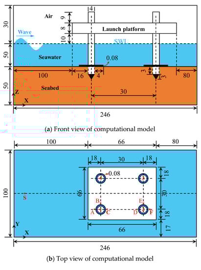
Figure 1.
Schematic diagram of the geometric model for the jack-up offshore platform and its seabed foundation (unit: m). The labeled positions: A (115.95, 35, 50), B (118, 37.05, 50), C (120.05, 35, 50), D (145.95, 35, 50), E (148, 37.05, 50), F (150.05, 35, 50), and S (0, 50, 50), are several typical positions used for subsequent analysis of computational results.
The length of the seabed foundation is 246 m, the width is 100 m, and the depth is 50 m. The shortest distance from the center of the four pile legs to the left and right seabed boundary is 98 to 118 m, and the shortest distance to the front and back seabed boundary is 35 m. This distance is more than eight times the diameter of the pile legs. The adverse effects of the fixed lateral boundary of the seabed on the dynamic response of the seabed around the offshore platform can be eliminated as much as possible.
3.2. Hydrodynamic Model
OlaFlow is used to simulate the action of ocean waves on the offshore jack-up platforms, and determine the wave impact on the seabed foundation, providing the hydrodynamic loading boundary condition for numerically computing the dynamic response of the jack-up platform and its seabed foundation. The numerical wave-maker is located on the left side of the jack-up platform, and is 120 m away from the left lateral side of the box-type platform. The water depth is set as 50 m in the computation. The distance from the static water surface to the bottom of the upper platform is 10 m.
Figure 2 shows the generated mesh in the zone around the jack-up offshore platform in the wave model. To more credibly simulate and capture the complex motion process of waves, the meshes in the zone where the wave-free surface moves and in the zone around the jack-up platform are refined. The specific mesh size is listed in Table 1. A total of 11,210,090 finite volume elements are used to discretize the fluid domain (including the sea water and air). The maximum mesh size in the zone far away from the jack-up platform is 3.25 m, while it is 0.4 m in the zone near the jack-up platform. In theory, the finer the mesh, the more reliable the computational results. However, the finer the mesh, the more computing resources are required, and the computing cost is extremely expensive. This requires us to find a point to balance the computing cost and the computing scale under the condition of the available computing resources. In this study, the number of meshes in the wave model is more than 11,000,000. It means that the computing scale is not small. In order to obtain credible computational results in a reasonable time, a super-cluster Huawei KunLun9016 is utilized. There is a total of 512 threads that can be used in parallelization for OlaFlow. The CPU type is Intel Xeon E7-4850 v4 and its frequency is 2.10 GHz. The total size of memory available in the cluster is 512 GB. The total time for each case is about 48 h.
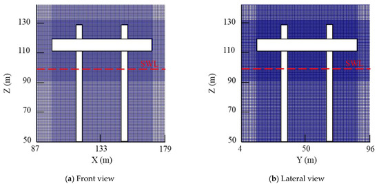
Figure 2.
Generated mesh in the wave model around the jack-up offshore platform.

Table 1.
Setting of grid size in the wave model.
The parameters of the ocean waves generated in the hydrodynamics modeling are listed in Table 2. In the actual operation conditions, the jack-up offshore platform is generally not used in extreme wave conditions, because the jack-up platform will violently vibrate with a great displacement amplitude under harsh marine hydrodynamic environments, which would have a disastrous impact on some tasks for the jack-up platform, such as the satellite launch. Therefore, this study does not investigate the stability of the jack-up platform under very extreme waves, but focuses on some conventional ocean waves. In the modeling, the third-order Stokes wave theory is used to generate the target wave trains. The motion of ocean waves is controlled by the VARANS equation, and the RNG k-ε turbulence model is adopted to describe the turbulence in the wave field. Furthermore, the end of the computation domain is set as the wave-absorbing boundary, to avoid the reflection of incident waves at the end boundary of the fluid domain.
Table 2.
Parameters of the ocean waves in hydrodynamics modeling.
3.3. Model for the Jack-Up Platform-Seabed Foundation Dynamics
The finite element mesh for the jack-up platform-seabed foundation system is shown in Figure 3. There are a total of 394,697 elements. Among them, the seabed foundation is discretized by the three-dimensional eight-nodes element C3D8P, which includes the degree of freedom for pore pressure. There are a total of 369,308 elements and 388,740 nodes in the domain of the seabed foundation. Since the seabed foundation surrounding the pile legs of the jack-up platform is a key area of concern, the mesh in these zones is refined, and the minimum mesh size is only 0.1 m. In the zone far away from the pile legs of the jack-up platform, the mesh size is generally 0.5 to 3.5 m. The jack-up platform is discretized by the three-dimensional eight-nodes element C3D8 and the ten-nodes tetrahedral element C3D10, in which there is no degree of freedom for pore pressure. There are a total of 20,500 C3D8 elements and 4889 C3D10 elements in the domain of the jack-up offshore platform.
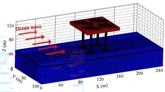
Figure 3.
Generated mesh for the offshore jack-up platform and its seabed foundation (noted: the four pile legs are thin-walled and hollow).
In this study, the Biot “u-p” equation is used to describe the stress balance and pore water seepage for the seabed foundation. Meanwhile, the Mohr-Coulomb (MC) model is used to describe the mechanical behavior of the seabed soil. It should be noted that the MC model is just an ideal elastoplastic model that can only approximately describe the behavior of soil. The physical property parameters of the seabed soil used are listed in Table 3. It is known that there are many constitutive soil models available in the numerical simulation of geotechnical engineering problems. Among them, the Mohr-Coulomb model is one of the most widely used in practical engineering design. The yield surface of the MC model is:
where σ is the normal stress, τ is the shear stress, C is the cohesion of soil, and φ is the internal friction angle of soil. The expression of the MC model in the principal stress space is:
where and are the maximum and minimum principal stresses, respectively.
Table 3.
Physical property parameters of seabed foundation soil.
Figure 4 shows the shape of the yield surface of the MC model in the principal stress space and on the π plane. It can be seen in Figure 4 that the yield surface of the MC model in the principal stress space is an open hexagonal pyramid, and its projection on the π plane is a hexagon. In numerical modeling, since the plastic flow direction at the six vertexes is not unique, it will bring great difficulty to the numerical computation. However, the ABAQUS software has smoothed the six vertexes of the hexagon, guaranteeing the uniqueness of the plastic flow direction on the yield surface of the MC model. As a result, the numerical stabilization in modeling can be greatly improved.
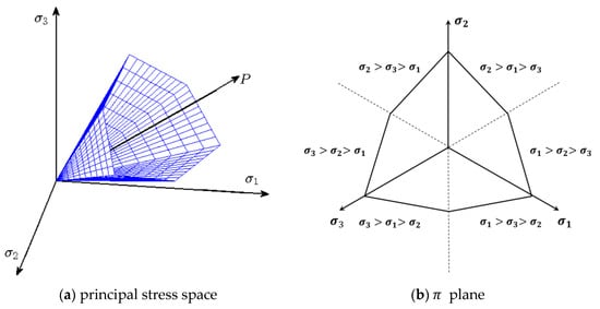
Figure 4.
Yield surface of the Mohr-Coulomb soil model in the principal stress space and π plane.
The designed structural weight of the whole jack-up platform is 4000 t. The load imposed on the upper surface of the box-type platform is set as 4000 t, to consider the weight of other functional structures and the active loads on the platform. Since the end of the pile legs are designed as tapered closed form, the four partially submerged pile legs can provide strong buoyancy, which is beneficial to reduce the requirement for the bearing capacity of the seabed foundation. According to the water depth and the geometrical size of the model, the buoyancy of the whole jack-up platform is estimated as 25,120 kN. Considering the dead weight of the whole platform, and the vertical load on the upper surface of the box-type platform, as well as the buoyancy effect, the equivalent density of the entire jack-up platform is determined to be 41 . Since the whole Jack-up platform is made of steel, the elastic model is adopted to describe its behavior, with Young’s modulus = 200 GPa and Poisson’s ratio = 0.25. The governing equation for the dynamics of the jack-up platform is degraded from the Biot dynamic equation when the porosity of materials and the pore pressure are ignored.
When simulating the dynamic response of the jack-up platform and its seabed foundation under the wave loads, the applied boundary conditions are as follows:
(1) The displacement in the x direction on the left and right lateral sides of the seabed foundation is zero, and the displacement in the y direction on the front and back lateral sides of the seabed foundation is also zero:
(2) The bottom of the seabed foundation is fixed with displacements in the x, y and z directions, and the bottom of the seabed is an impervious boundary.
(3) Hydrodynamic boundary: at each time step, the wave impact (including hydrostatic pressure and hydrodynamic pressure) determined by the OlaFlow model is imposed to the outer surface of the jack-up platform and the surface of the seabed foundation.
(4) A node-to-node tie contact is set on the contact surface between the four pile legs of the jack-up platform and its surrounding seabed soil. It means that the deformation of these pile legs and the seabed foundation is considered to be continuous at their contact surfaces.
4. Hydrodynamics around the Jack-Up Platform
4.1. Wave Profiles
Figure 5 demonstrates the evolution of the wave-free surface around the jack-up platform in one period in Case 1 (H = 7 m, d = 50 m, T = 15 s). It can be seen in Figure 5 that a wave trough reaches exactly below the platform at t = 54.9 s, and at t = 62.4 s (after 1/2 wave period), a wave crest reaches exactly below the platform. Since the wave height is not very high, the period is long, and the wavelength is long as well, the change of the wave shape after the collision between wave crests and the pile legs is not particularly significant. It is also observed in Figure 5 that the wave did not contact the bottom of the box-type platform in Case 1, indicating that the wave and the jack-up platform did not collide violently under this condition, which is extremely conductive to the normal service ability of the jack-up platform.
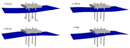
Figure 5.
Wave profiles at four typical times during one wave period around the jack-up platform.
4.2. Distribution of Velocity and Pressure
In the analysis of the modeling results for three-dimensional cases, in order to make the results in the computational domain clearly visible to readers, it is better to display the results by sectioning the computational domain. Here, a plane at Y = 50 m is used to cut the seawater-platform domain, and then the computational results are displayed on the XZ plane at Y = 50 m.
Figure 6 shows the distributions of the wave-induced dynamic pressure (note: the initial hydrostatic pressure is excluded) and the velocity in the zone around the jack-up platform at t = 56.4 s (the time when a wave trough is under the platform) and t = 62.4 s (the time when a wave crest is under the platform). It is observed that the hydrodynamic pressure below the wave trough is negative, while it is positive below the wave crest, and the magnitude of the hydrodynamic pressure exceeds 40 kPa. This hydrodynamic pressure is the environmental load that drives the vibration response and even the instability of the offshore platform and seabed foundation. The velocity distribution in Figure 6 shows that the maximum wave speed in the x direction is about 2.5 m/s; meanwhile, the maximum wave speed in the z direction is about 2 m/s.
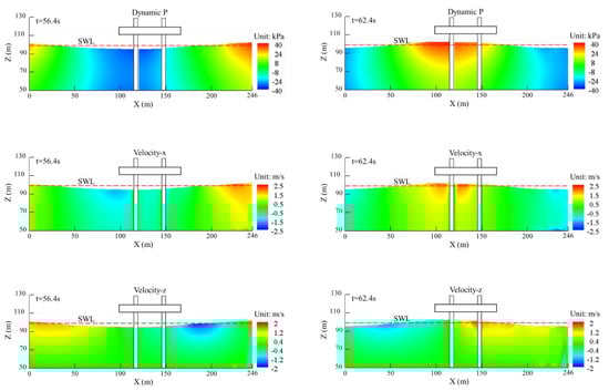
Figure 6.
Distribution of the wave-induced pressure and velocity at t = 56.4 s and t = 62.4 s around the offshore platform on the section Y = 50 m in Case 1 (H = 7 m, d = 50 m, T = 15 s).
Figure 7 shows the evolutionary time history of the wave profiles at the different typical positions A–F and S around the pile legs of the jack-up platform. As can be seen from the wave profile at S shown in Figure 7, the wave generated by the numerical wave-maker is stable, the waveform is close to a simple harmonic wave, and the wave height and wave period can reach the expected values. It has been shown in Figure 1 that the points A to F are located around the pile legs of the platform. Compared with the regular waveform at S, the waveform at A–F is no longer close to a simple harmonic wave, and the wave height slightly increases, presenting a certain degree of nonlinearity, but wave breaking does not occur. This phenomenon indicates that the pile legs of the jack-up platform have hindered the wave propagation, and the wave trains have a certain degree of reflection and superposition. Overall, the wave motion around the pile legs becomes complicated. It can also be seen in Figure 7 that the wave heights at A and D are higher than those at E and F, because the points A and D are respectively located at the head-wave side of the No. 1 and No. 2 pile legs, where waves will climb after interacting with the two pile legs.
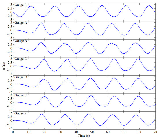
Figure 7.
Evolutionary time history of wave profiles at different typical positions around the pile legs of the jack-up platform (note: the typical positions A–F and S have been labeled in Figure 1b).
4.3. Wave Impact on Platform and Foundation
Taking Case 1 (H = 7 m, d = 50 m, T = 15 s) as a typical case, the characteristics of the wave impact on the surface of the seabed foundation and the jack-up platform will be analyzed in this section. Figure 8 illustrates the time history of wave impact at different typical positions on the seabed surface. It is observed that the magnitudes of wave impact at S and A–F on the seabed surface are basically the same, about 20 kPa. Compared with the evolutionary time history of wave profiles at the corresponding positions demonstrated in Figure 7, the time history of wave impact in Figure 8 is smoother and closer to a simple harmonic wave. It is indicated that the nonlinearity in the time history of wave impact imposed on the surface of the seabed foundation is weak if there is no wave breaking.
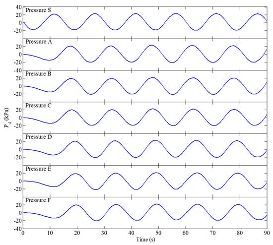
Figure 8.
Time history of wave impact at different typical positions on the seabed surface in Case 1 (H = 7 m, d = 50 m, T = 15 s).
Figure 9 shows the time history of wave impact at the six typical points which are located at 2 m above the initial static water surface and on the pile legs in Case 1 (H = 7 m, d = 50 m, T = 15 s). It is found in Figure 9a that the wave impact on A is significantly greater than that on B and C, because A is located on the head-wave side. The maximum wave impact on A is about 24 kPa. For the point C which is at the back-wave side, there is only little difference in the magnitude of wave impact with that on B. It can also be found in Figure 9b that the wave impact on D, which is at the head-wave side of the No. 2 pile leg, is greater than that on E and F. Comparing Figure 9a,b, it is observed that the wave impact on A basically had no significant difference in magnitude with that on D, where the points A and D are at the head-wave side of the No. 1 and No. 2 pile leg, respectively.
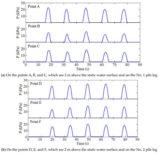
Figure 9.
Time history of the wave impact on the different positions on the pile legs 2 m above the static water surface in Case 1 (H = 7 m, d = 50 m, T = 15 s).
In addition to the wave impact on several individual points on the pile legs, the resultant force of the wave impact on these pile legs of the jack-up platform is also worth exploring. Figure 10 shows the time history of the resultant force of wave impact on the No. 1 and No. 2 pile legs of the jack-up platform under different wave conditions. It is observed that the wave-induced resultant force on the pile legs is positively related to the wave height. When the wave height H = 3 m, H = 5 m, and H = 7 m, the maximum wave-induced resultant force on the No. 1 pile leg is about 400, 600, and 800 kN, respectively. When the wave height H = 7 m, the maximum resultant force on the No. 2 pile leg reaches about 700 kN. Therefore, the total resultant force on the whole offshore platform will reach about 3000 kN in Case 1 (H = 7 m, d = 50 m, T = 15 s). This magnitude of the resultant force imposed by ocean wave is considerable, and it may cause significant sloshing to the jack-up platform (the amplitude of sloshing will be quantitatively analyzed later), which would further affect the service performance of the offshore platform when carrying out engineering tasks.
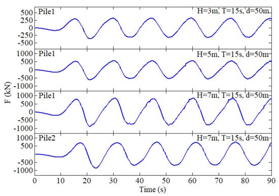
Figure 10.
Time history of the wave-induced resultant force on the No. 1 and No. 2 pile legs of the jack-up platform under different wave conditions.
5. Dynamics of Jack-Up Platform and Seabed Foundation
5.1. Initial State
In the long geological history, the original seabed must have undergone a consolidation settlement process under the self-weight and the hydrostatic pressure. After the jack-up platform is installed on the seabed foundation, under the gravity of the jack-up platform structure, the structure-seabed foundation system will reach a new equilibrium state. This equilibrium state should be used as the initial state to analyze the dynamic response of the jack-up offshore platform and its seabed foundation under environmental loading.
In order to display the distribution of pore pressure and effective stress in the initial state more clearly, the computational results are shown on several sections in the 3D computation domain here. Figure 11 shows the distribution of pore pressure, effective stress, and shear stress in the jack-up platform and its seabed foundation in the initial state considering the self-weight and hydrostatic pressure. It is observed that the distribution of pore pressure is layered in the seabed foundation. There is only hydrostatic pressure and no excess pore pressure at all. Since the offshore platform is made of completely impermeable steel, the pore pressure in the platform and pile legs is zero. From the distribution of and , it can be seen that the influence of the dead weight of the jack-up platform structure on the distribution of effective stress in the seabed foundation is limited in a small region around the pile legs, and the effective stress is also distributed in layers in the seabed foundation far away from the platform structure. From the distribution of the shear stress and , it can be seen that the shear stress in the seabed foundation near the pile legs is significant, and there are shear stress-concentrated zones with a maximum magnitude exceeding 20 kPa.
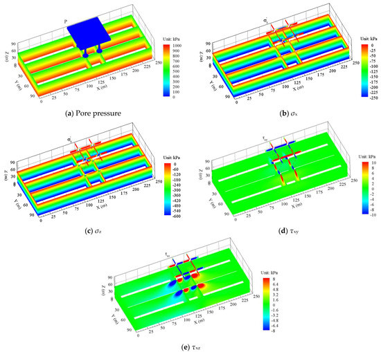
Figure 11.
Distribution of pore pressure, effective stress, and shear stress in the offshore platform and its seabed foundation in the initial equilibrium state.
Figure 12 shows the displacement distribution of the jack-up platform and seabed foundation in the initial state. It is observed that there is only the horizontal displacement with the magnitude of millimeter inside the seabed foundation under the gravity of the platform structure. This magnitude of horizontal displacement is actually very small. For such a large-scale platform structure, it basically could be ignored. However, in the vertical direction, the initial settlement of the platform structure is significant, reaching 120 mm.
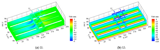
Figure 12.
Displacement distribution in the x and z directions in the initial state.
5.2. Displacement, Effective Stresses, and Pore Pressure
Taking the above-determined initial state as the initial condition, and when the wave impact is applied to the jack-up platform and its seabed foundation through the OlaFlow-ABAQUS coupling model, the wave-induced dynamic response of the jack-up platform and its seabed foundation is studied here.
As is known, the wave-induced dynamic displacement of offshore structures is an important indicator to evaluate the service performance and the stability of offshore platforms. If the dynamic displacement is great, the jack-up platform may not be suitable for carrying out its engineering tasks because of the danger of capsizing. Therefore, the analysis of the displacement response of the jack-up platform is of significance for the evaluation of its service performance and stability.
Figure 13 shows the time history of the horizontal displacement at the top of the jack-up platform under three conventional wave conditions. It is observed that the jack-up platform only has a small amplitude of periodic sloshing without significant residual displacement under the three wave conditions, in which the wave height H = 3 m, H = 5 m, and H = 7 m, respectively. The maximum amplitude of sloshing is about 5.0, 6.0, and 8.0 cm, respectively. This result indicates that there is no plastic deformation zone in the seabed foundation near the platform legs under the action of both the cyclic wave loading and the cyclic extrusion by the pile legs. Otherwise, there should be residual displacement for the jack-up platform. Therefore, the jack-up platform has good stability under the three conventional wave conditions. However, whether the periodic sloshing with an amplitude of 5.0–10.0 cm affects the normal service performance of the jack-up platform depends entirely on the requirements set by the engineering tasks; for example, a satellite launch mission maybe cannot be carried out when the wave height is H = 7 m, and the jack-up platform sloshes periodically with an amplitude of 10 cm.
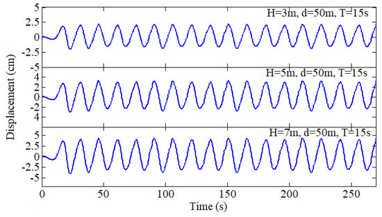
Figure 13.
Time history of the horizontal displacement at the top of the jack-up platform under three conventional wave conditions.
Figure 14a shows the wave surface when a wave trough reaches the jack-up platform in Case 2 (H = 5 m, d = 50 m, T = 15 s). Meanwhile, Figure 14b–g show the distribution of the wave-induced dynamic pore pressure, effective stress, and shear stress in the jack-up platform and its seabed foundation at this moment. It can be seen in Figure 14b that the dynamic pore pressure in the seabed below the platform is significant at t = 54.9 s, and the maximum dynamic pore pressure on the surface of the seabed is about 15 kPa, and the sign is negative. This means that an upward seepage is occurring in the seabed under the platform at this moment, the pore water in the seabed is flowing into the seawater, and the seabed in this zone is having an upward movement trend, as shown in Figure 15b. It can be seen in Figure 14c–e that the vertical dynamic effective stress, , in the superficial layer of the seabed under the platform is positive (note: the positive value means tension in this study), indicating that this seabed zone is in a state of dynamic tension in vertical. The distribution form of the dynamic is basically the same as that of the dynamic , but the dynamic is in a compressive state in horizontal. The dynamic effective stress, , is mainly concentrated in the zone near the interface between the box-type platform and the four pile legs. It is also seen in Figure 14f,g that the dynamic shear stresses and are also mainly concentrated in the zone around the contact surface between the four pile legs and the seabed foundation, and the magnitude is about 10 kPa.
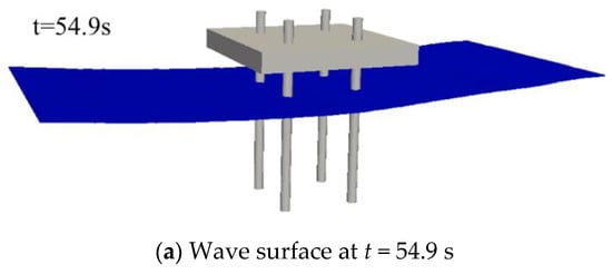
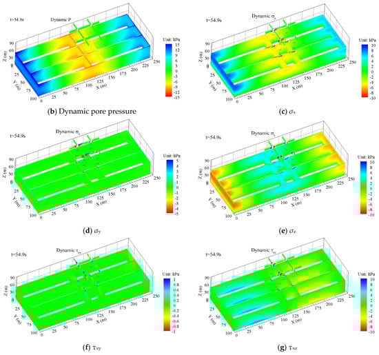
Figure 14.
Wave surface, and the distribution of dynamic pore pressure, effective stress, and shear stress in the jack-up platform and its seabed foundation when a wave trough reaches the jack-up platform in Case 2 (t = 54.9 s).
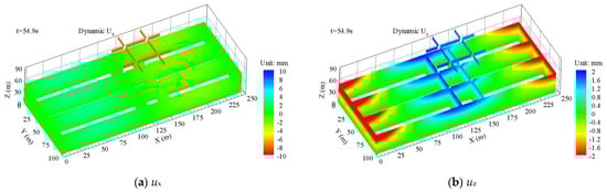
Figure 15.
Distribution of the wave-induced dynamic displacement in the x and z directions in the jack-up platform and its seabed foundation when a wave trough reaches the platform at t = 54.9 s (H = 5 m, d = 50 m, T = 15 s).
Figure 15 shows the wave-induced dynamic displacement distribution in the jack-up platform and its seabed foundation when a trough reaches below the platform under the condition of wave height H = 5 m. It is observed that when the wave trough arrives, the wave-induced horizontal displacement at the top of the jack-up platform is opposite to the direction of the wave, and the displacement magnitude is relatively significant. The specific magnitude has been illustrated in Figure 13. However, the wave-induced horizontal displacement in the seabed foundation is not significant. It can be seen in Figure 15b that the upper seabed foundation under the wave trough has an upward displacement, and the maximum value can exceed 2 mm. Meanwhile, the upper seabed foundation under the wave crests also has a maximum downward displacement of about 2 mm. In general, it is known that the horizontal displacement of a jack-up offshore platform under the action of a wave is greater than its vertical displacement, while the horizontal displacement in the seabed foundation is much smaller than its vertical component.
5.3. Liquefaction in Seabed Foundation
There are two mechanisms for the wave-induced seabed liquefaction that have been widely verified in previous experiments and numerical simulations. The key point to distinguish the two liquefaction mechanisms is the different ways of generating pore water pressure. The first mechanism is the residual liquefaction, which is related to the accumulation of pore pressure in the seabed under cyclic loading. Residual liquefaction can occur under the attack of ocean waves and earthquakes. The second mechanism is the momentary liquefaction, which can only occur in a very dense seabed under wave troughs. Seabed liquefaction is an important factor affecting the stability of marine structures built on a seabed foundation. Here, the wave-induced momentary liquefaction in the seabed foundation of jack-up platforms will be analyzed.
The judgment criterion for the momentary liquefaction adopted in this study is based on the following three-dimensional stress-based criterion:
where , , and are the current effective stresses at a point in the seabed foundation. The physical meaning of Equation (6) is that seabed soil is in a tensile state when the current mean effective stress at a point is greater than or equal to zero, and it can be considered that the seabed soil at this point has become liquefied. The distribution of the liquefaction zone in the seabed foundation in Case 2 is shown in Figure 16.
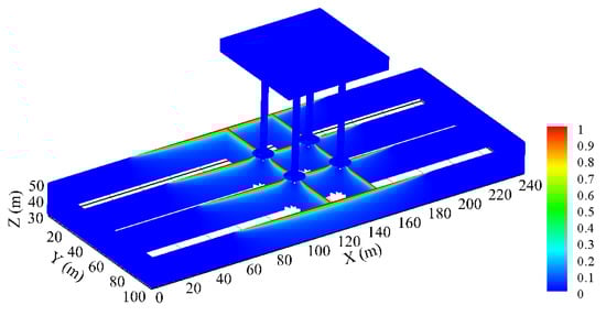
Figure 16.
Predicted liquefaction zone in the seabed foundation when a wave trough reaches the jack-up offshore platform at t = 54.9 s in Case 2 (H = 5 m, d = 50 m, T = 15 s) (note: the red zone is the liquefaction zone).
In Figure 16, it is observed that liquefaction only occurs in the superficial layer of the seabed foundation, and the maximum liquefaction depth is about 1 m. It is well-known that a typical feature of momentary liquefaction is the periodic appearance and disappearance in the process of wave motion. Specifically, momentary liquefaction occurs in the superficial layer of the seabed foundation surrounding the pile legs of the jack-up platform when each wave trough reaches the platform. When the momentary liquefaction occurs, the soil particles in the superficial layer of the seabed foundation are in a suspended state, and easily transported by scouring. As a result, some large-scale scouring pits around the pile legs would more easily appear, which has an adverse effect on the long-term stability of the offshore platform [25,26,27].
It can also be seen in Figure 16 that no momentary liquefaction occurs in the seabed directly below the four spudcans. It is indicated that the spudcans installed on the tip of the pile legs can not only reduce the base pressure of the foundation, but also inhibit the occurrence of momentary liquefaction in the surrounding seabed soil, which could make the offshore platform structure more stable in service.
6. Conclusions
In this study, the self-developed coupling model OlaFlow-ABAQUS for the fluid–structure–seabed interaction (FSSI) was used to explore the dynamic response characteristics of a jack-up offshore platform and its seabed foundations under three conventional wave conditions (wave height was 3, 5, and 7 m, respectively). Based on the numerical results, the following conclusions were obtained:
(1) There was only periodic sloshing with a small amplitude occurring under the three conventional wave conditions for the jack-up platform. The maximum sloshing amplitude was up to 8 cm, and no obvious residual displacement occurred for the jack-up offshore platform. It was indicated that there was no plastic deformation zone in the seabed foundation surrounding the pile legs of the jack-up platform. It can thus be seen that the jack-up offshore platform has excellent stability under conventional wave conditions. However, whether the periodic sloshing of the platform structure affects its normal performance highly depends entirely on the requirements set by the engineering task itself, which needs to be analyzed on a case-by-case basis.
(2) Under conventional wave loading, momentary liquefaction occurred in the seabed foundation around the pile legs of the jack-up platform, and the maximum liquefaction depth was about 1 m. The spudcans installed on the tips of the pile legs of the jack-up platform effectively inhibited the occurrence of liquefaction in their surrounding seabed soil, making the offshore platform structure more stable under wave impact.
(3) An important assumption in this study is that the behavior of seabed soil can be described by the Mohr-Coulomb soil model. It implies that the seabed foundation is assumed to be a type of geotechnical material with ideal elastoplastic behavior. As a result, the pore pressure build-up, and the related softening and residual liquefaction of the seabed foundation, could not be captured in this study. More complicated elastoplastic soil models could be used in the future to more reliably investigate the wave-induced dynamics of the jack-up offshore platform.
(4) It was indicated by this study that the coupling model OlaFlow-ABAQUS for the FSSI problem is feasible, and has some advantages to study the dynamic response and to evaluate the stability of large-scale marine structures and their seabed foundations under ocean waves.
Author Contributions
Conceptualization, H.Y. and J.Y.; Data curation, D.Y. and Z.Y.; Formal analysis, H.Y., D.Y. and J.Y.; Funding acquisition, H.Y. and Z.Y.; Investigation, H.Y. and D.Y.; Methodology, D.Y. and J.Y.; Project administration, Z.Y.; Supervision, J.Y.; Writing—original draft, D.Y.; Writing—review & editing, J.Y. All authors have read and agreed to the published version of the manuscript.
Funding
This work is financially supported by the Chinese Military Logistics Scientific Research Program (CZZ19J013), as well as by the National Natural Science Foundation of China (No. 51879257).
Institutional Review Board Statement
Not applicable.
Informed Consent Statement
Not applicable.
Data Availability Statement
Data that support the findings of this study are available from the corresponding author upon reasonable request.
Conflicts of Interest
The authors declare no conflict of interest.
References
- Abrishamchi, A.; Younis, B.A. LES and URANS predictions of the hydrodynamic loads on a tension-leg platform. J. Fluids Struct. 2012, 28, 244–262. [Google Scholar] [CrossRef]
- Li, L.; Ruzzo, C.; Collu, M.; Gao, Y.; Failla, G.; Arena, F. Analysis of the coupled dynamic response of an offshore floating multi-purpose platform for the Blue Economy. Ocean. Eng. 2020, 217, 107943. [Google Scholar] [CrossRef]
- Liu, W.Q.; Guo, X.X.; Zhang, G.W.; Wu, H.; Li, Y.; Song, X.M.; Liu, Z.G. Experiment and numerical investigation on structural response of a FMRC hexagon enclosed platform in waves. Ocean. Eng. 2021, 233, 108998. [Google Scholar] [CrossRef]
- AIMashan, N.; Neelamani, S.; AI-Houti, D. Experimental investigations on wave impact pressures under the deck and global wave forces and moments on offshore jacket platform for partial and full green water conditions. Ocean. Eng. 2021, 234, 109324. [Google Scholar] [CrossRef]
- Zhao, S.X.; Bi, C.W.; Zhang, D.L.; Yu, H.F. Hydrodynamic response analysis of a 10,000-ton offshore electrical platform in waves using a modified finite element model. Ocean. Eng. 2021, 233, 109194. [Google Scholar] [CrossRef]
- Xie, Y.C.; Huang, J.T.; Li, X.K.; Tian, X.J.; Liu, G.J.; Leng, D.X. Experimental study on hydrodynamic characteristics of three truss-type legs of jack-up offshore platform. Ocean. Eng. 2021, 234, 109305. [Google Scholar] [CrossRef]
- Ye, J.H.; Wang, G. Numerical simulation of the seismic liquefaction mechanism in an offshore loosely deposited seabed. Bull. Eng. Geol. Environ. 2016, 75, 1183–1197. [Google Scholar] [CrossRef]
- Yang, G.X.; Ye, J.H. Wave & current-induced progressive liquefaction in loosely deposited seabed. Ocean. Eng. 2017, 142, 303–314. [Google Scholar]
- Yang, G.X.; Ye, J.H. Nonlinear standing wave-induced liquefaction in loosely deposited seabed. Bull. Eng. Geol. Environ. 2018, 77, 205–223. [Google Scholar] [CrossRef]
- Ye, J.H.; Jeng, D.S.; Wang, R.; Zhu, C.Q. Numerical simulation of the wave-induced dynamic response of poro-elastoplastic seabed foundations and a composite breakwater. Appl. Math. Model. 2015, 39, 322–347. [Google Scholar] [CrossRef]
- Mizutani, N.; Mostafa, A.M.; Iwata, K. Nonlinear regular wave, submerged breakwater and seabed dynamic interaction. Coast. Eng. 1998, 33, 177–202. [Google Scholar] [CrossRef]
- Mostafa, A.M.; Mizutani, N.; Iwata, K. Nonlinear wave, composite breakwater, and seabed dynamic interaction. J. Waterw. Port Coast. Ocean. Eng. 1999, 125, 88–97. [Google Scholar] [CrossRef]
- Liu, X.F.; García, M.H. Numerical Investigation of Seabed Response Under Waves with Free-surface Water Flow. Int. J. Offshore Polar Eng. 2007, 17, ISOPE-07–17–2–097. [Google Scholar]
- Ye, J.H.; Jeng, D.S.; Wang, R.; Zhu, C.Q. A 3-D semi-coupled numerical model for fluid-structures-seabed-interaction (FSSI-CAS 3D): Model and verification. J. Fluids Struct. 2013, 40, 148–162. [Google Scholar] [CrossRef]
- Ye, J.H.; Jeng, D.S.; Wang, R.; Zhu, C.Q. Validation of a 2-D semi-coupled numerical model for fluid-structure-seabed interaction. J. Fluids Struct. 2013, 42, 333–357. [Google Scholar] [CrossRef]
- Jeng, D.S.; Ye, J.H.; Zhang, J.S.; Liu, P.L.F. An integrated model for the wave-induced seabed response around marine structures: Model verifications and applications. Coast. Eng. 2013, 72, 1–19. [Google Scholar] [CrossRef]
- Ye, J.H.; He, K.P.; Zhou, L.J. Subsidence prediction of a rubble mound breakwater at Yantai port: A application of FSSI-CAS 2D. Ocean. Eng. 2021, 219, 108349. [Google Scholar] [CrossRef]
- Ye, J.H.; Wang, G. Seismic dynamics of offshore breakwater on liquefiable seabed foundation. Soil Dyn. Earthq. Eng. 2015, 76, 86–99. [Google Scholar] [CrossRef]
- Ye, J.H.; Jeng, D.S.; Liu, L.F. Breaking wave-induced response of composite breakwater and liquefaction in seabed foundation. Coast. Eng. 2014, 85, 72–86. [Google Scholar]
- Ye, J.H. Introduction to FssiCAS Software. Available online: http://www.fssi.ac.cn/FssiCAS.html (accessed on 7 November 2021).
- He, K.P.; Huang, T.K.; Ye, J.H. Stability analysis of a composite breakwater at Yantai port, China: An application of FSSI-CAS-2D. Ocean. Eng. 2018, 168, 95–107. [Google Scholar] [CrossRef]
- Ye, J.H.; Yu, D.W. ABAQUS–OlaFlow integrated numerical model for fluid–seabed–structure interaction. Mar. Struct. 2021, 78, 103016. [Google Scholar] [CrossRef]
- Mirzadeh, J.; Kimiaei, M.; Cassidy, M.J. Performance of an example jack-up platform under directional random ocean waves. Appl. Ocean. Res. 2016, 54, 87–100. [Google Scholar] [CrossRef] [Green Version]
- Moctar, O.E.; Schellin, T.E.; Jahnke, T.; Peric, M. Wave Load and Structural Analysis for a Jack-Up Platform in Freak Waves. J. Offshore Mech. Arct. Eng. 2009, 131, 021602. [Google Scholar] [CrossRef]
- Sweeney, M.; Webb, R.M.; Wilkinson, R.H. Scour Around Jack-up Rig Footings. In Offshore Technology Conference (OTC); Houston, TX, USA, 1988. [Google Scholar]
- Angus, N.M.; Moore, F.L. Scour repair methods in Southern North Sea. In Offshore Technology Conference; OnePetro: Richardson, TX, USA, 1982. [Google Scholar]
- Rudolph, D.; Bijlsma, A.C.; Bos, K.; Rietema, K. Scour around Spud Cans –Analysis of Field Measurements. In The Fifteenth International Offshore and Polar Engineering Conference; OnePetro: Richardson, TX, USA, 2005. [Google Scholar]
- Ghazi, Z.M.; Abbood, I.S.; Hejazi, F. Dynamic evaluation of jack-up platform structure under wave, wind, earthquake and tsunami loads. J. Ocean. Eng. Sci. 2022, 7, 41–57. [Google Scholar] [CrossRef]
- Zhang, Q.; Fang, T.Y.; Ye, G.L.; Liu, G.J.; Wang, R.; Tian, Y.H. Effect of sitting time on the breakout force of mat foundation on soft marine clay seabed. Ocean. Eng. 2021, 234, 108770. [Google Scholar] [CrossRef]
- Vlahos, G.; Cassidy, M.J.; Martin, C.M. Numerical simulation of pushover tests on a model jack-up platform on clay. Geotechnique 2011, 61, 947–960. [Google Scholar] [CrossRef]
- Yin, Q.L.; Zhai, J.J.; Dong, S. Predicting the overall horizontal bearing capacity of jack-up rigs using deck–foundation–soil-coupled model. Proc. Inst. Mech. Eng. Part M J. Eng. Marit. Environ. 2021, 235, 213–224. [Google Scholar] [CrossRef]
- Luo, W.Z.; Li, J.H. Effects of installation on combined bearing capacity of a spudcan foundation in spatially variable clay. Appl. Ocean. Res. 2022, 120, 103055. [Google Scholar] [CrossRef]
- Kim, J.H.; Jeong, Y.H.; Park, H.J.; Kim, D.S.; Kim, S.J.; Lee, S.W.; Chung, M.; Choi, J. Investigation of spudcan–soil interaction in a sloped seabed using centrifuge model tests. Géotechnique Lett. 2018, 8, 208–213. [Google Scholar] [CrossRef]
- Zhang, Q.; Zhou, X.L.; Wang, J.H.; Guo, J.J. Wave-induced seabed response around an offshore pile foundation platform. Ocean. Eng. 2017, 130, 567–582. [Google Scholar] [CrossRef]
- Lin, Z.; Pokrajac, D.; Guo, Y.K.; Jeng, D.S.; Tang, T.; Rey, N.; Zheng, J.; Zhang, J. Investigation of nonlinear wave-induced seabed response around mono-pile foundation. Coast. Eng. 2017, 121, 197–211. [Google Scholar] [CrossRef] [Green Version]
- Sui, T.; Zheng, J.; Zhang, C.; Jeng, D.S.; Zhang, J.; Guo, Y.; Heab, R. Consolidation of unsaturated seabed around an inserted pile foundation and its effects on the wave-induced momentary liquefaction. Ocean. Eng. 2017, 131, 308–321. [Google Scholar] [CrossRef] [Green Version]
- Sui, T.; Zhang, C.; Jeng, D.; Guo, Y.; Zheng, J.; Zhang, W.; Shi, J. Wave-induced seabed residual response and liquefaction around a mono-pile foundation with various embedded depth. Ocean. Eng. 2019, 173, 157–173. [Google Scholar] [CrossRef]
- Hsu, J.R.C.; Jeng, D.S. Wave-induced soil response in an unsaturated anisotropic seabed of finite thickness. Int. J. Numer. Anal. Methods Geomech. 1994, 18, 785–807. [Google Scholar] [CrossRef]
Publisher’s Note: MDPI stays neutral with regard to jurisdictional claims in published maps and institutional affiliations. |
© 2022 by the authors. Licensee MDPI, Basel, Switzerland. This article is an open access article distributed under the terms and conditions of the Creative Commons Attribution (CC BY) license (https://creativecommons.org/licenses/by/4.0/).