
RETRACTED: Laser Welding of UNS S33207 Hyper-Duplex Stainless Steel to 6061 Aluminum Alloy Using High Entropy Alloy as a Filler Material


Abstract
:1. Introduction
2. Materials and Methods
2.1. Materials
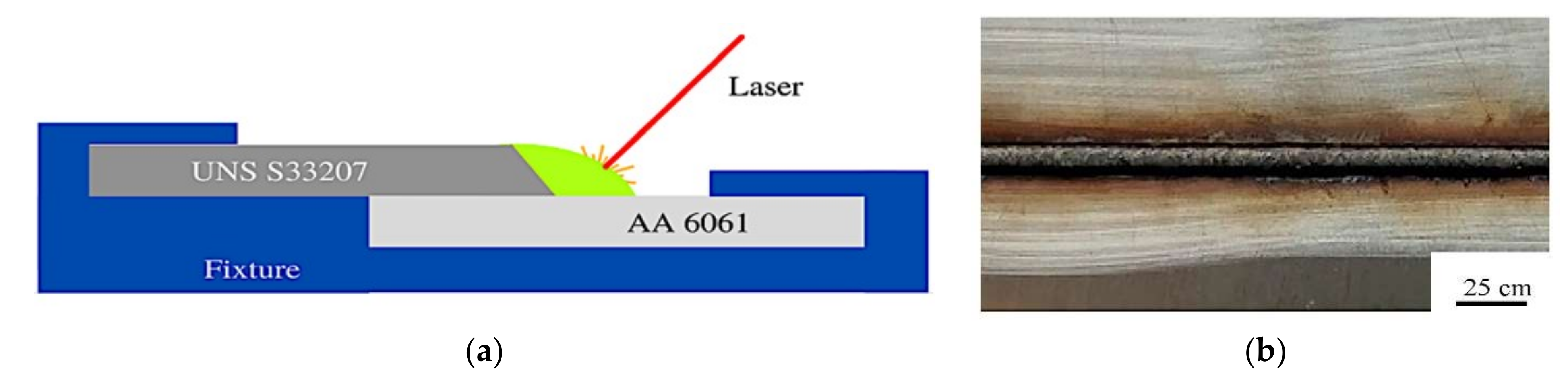
2.2. Laser Welding
2.3. Mechanical Testing
2.4. Materials Characterization
3. Results and Discussion
4. Conclusions
- In this laser welding experiment for joining UNS S33207 to aluminum alloy 6061, Fe5Co20Ni20Mn35Cu20 HEAs powder was chosen as the lap welding filler.
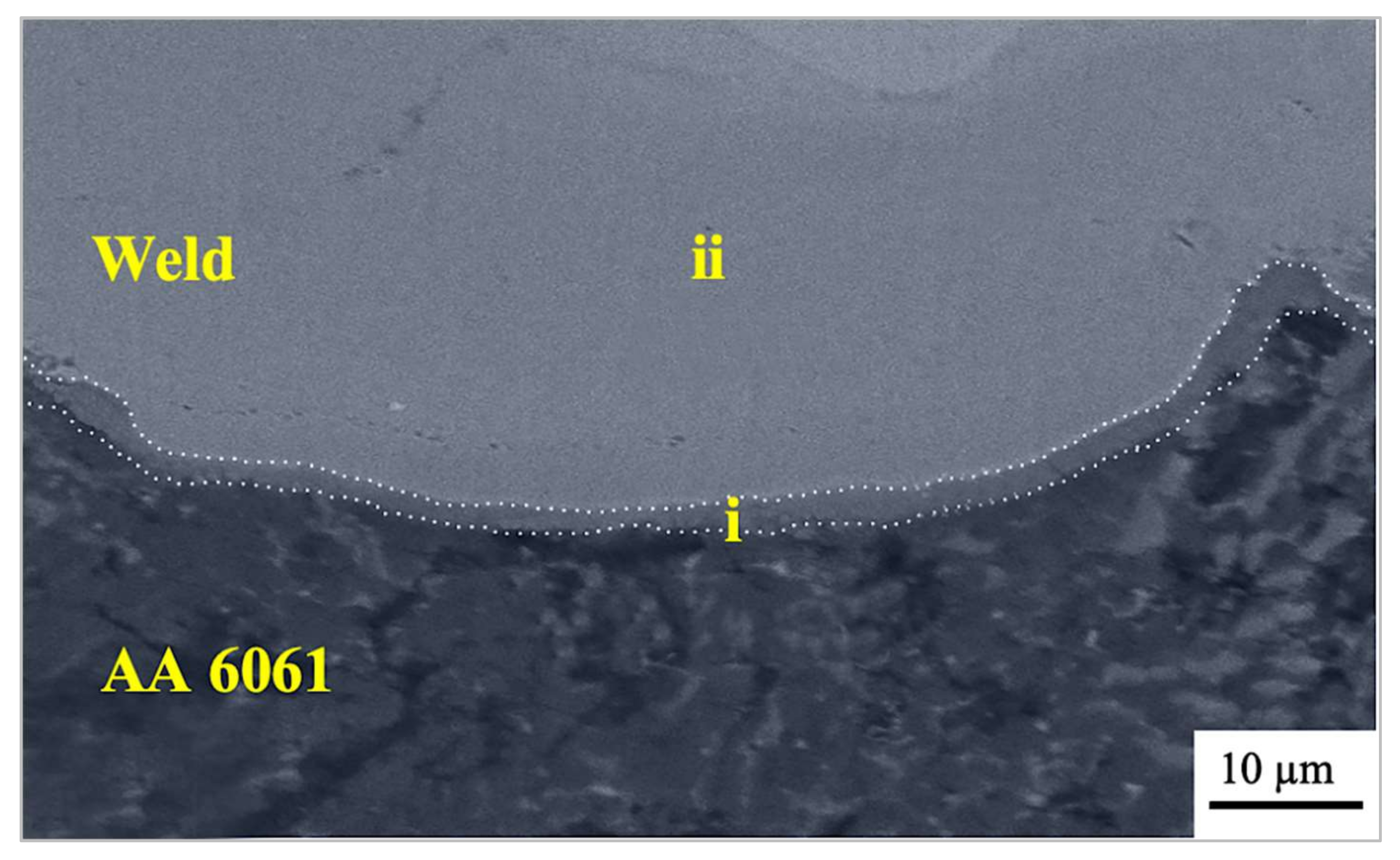
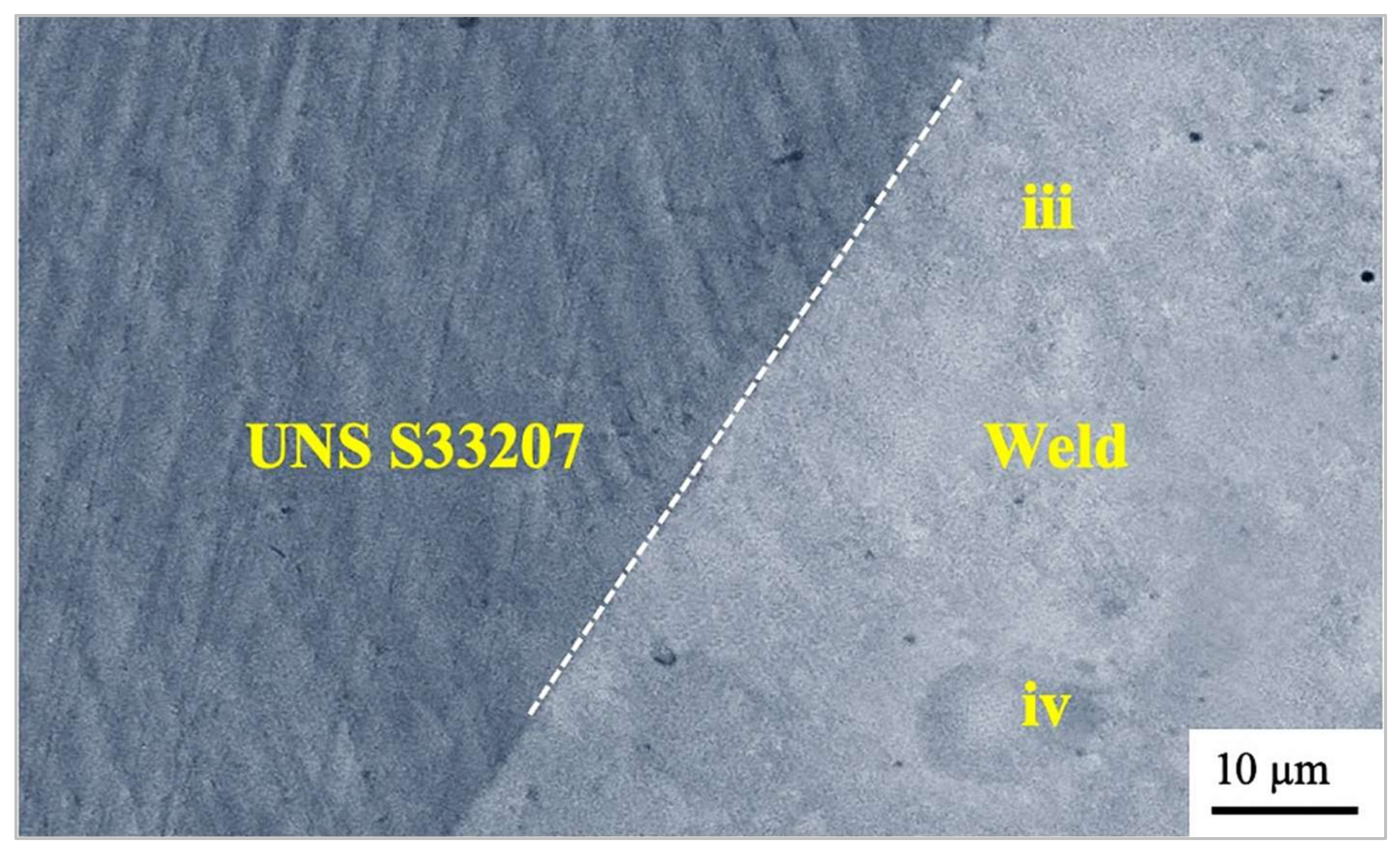
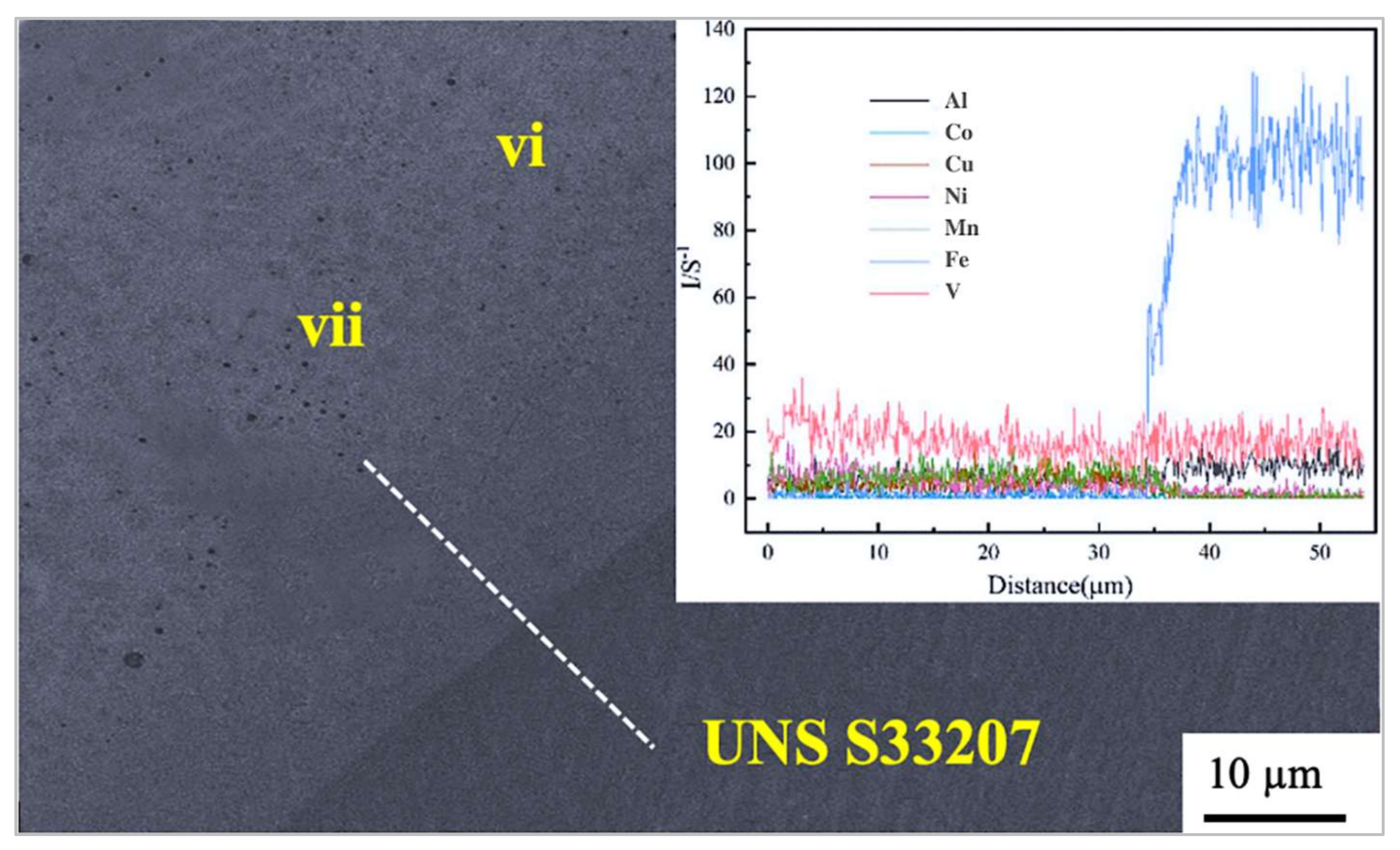
- The Fe and Al alloy’s mutual mixing and reaction were prevented by monitoring the melting quantity of the parent metal in the hyper-duplex stainless-steel side. Al/Fe intermetallic compounds were not identified in the joints weld zone.
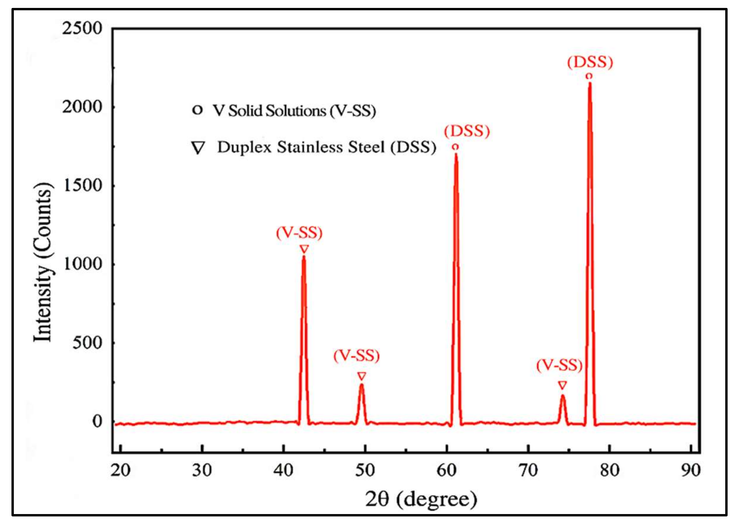
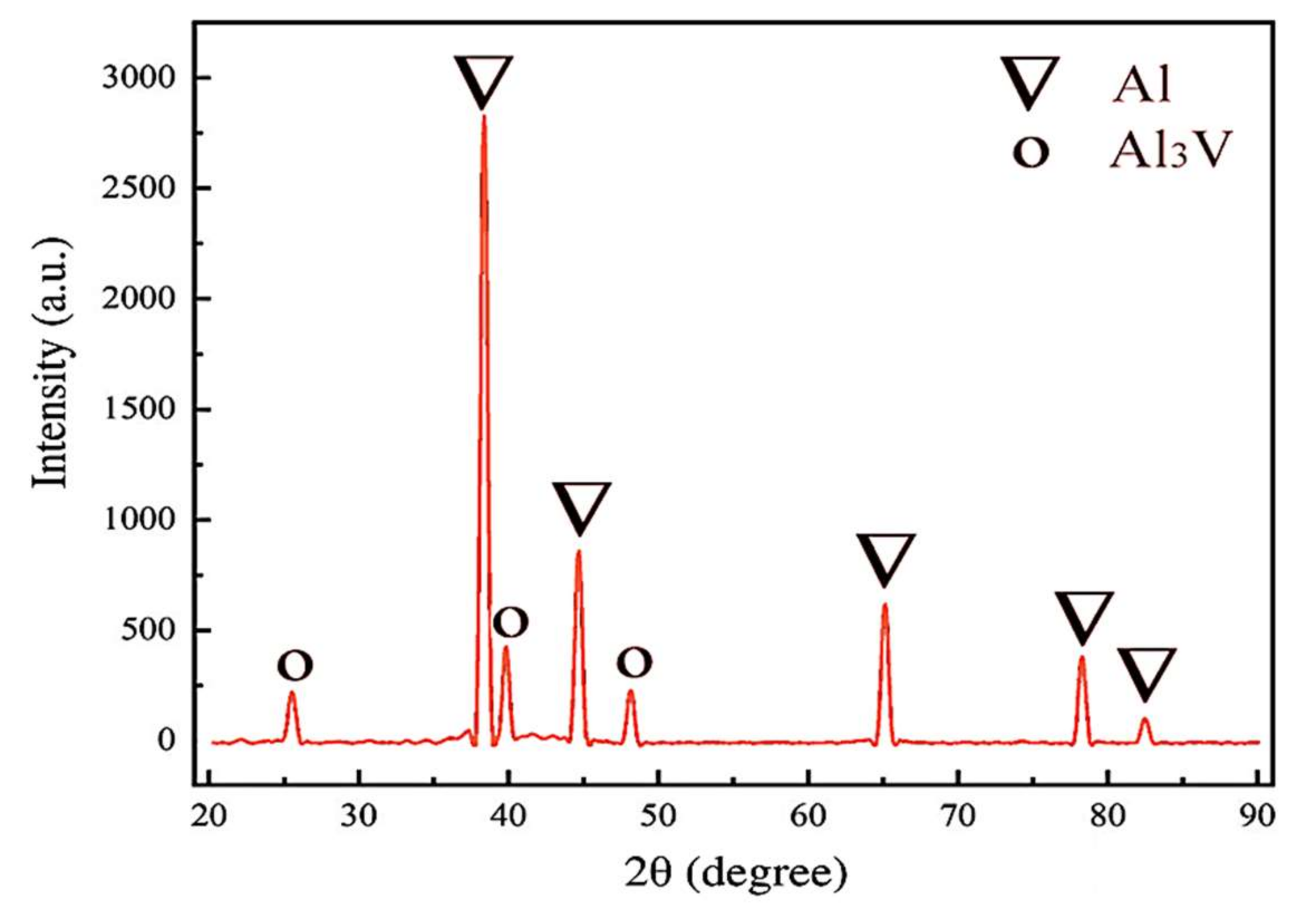
- The metallographic phases identified for the HEAs in the weld region were DSS and V solid solutions.
- The large entropy property of HEAs favored the production of arbitrary solid solutions over IMCs. As a result, the HEAs’ after-melting phase was comprised of DSS and V solid solutions.
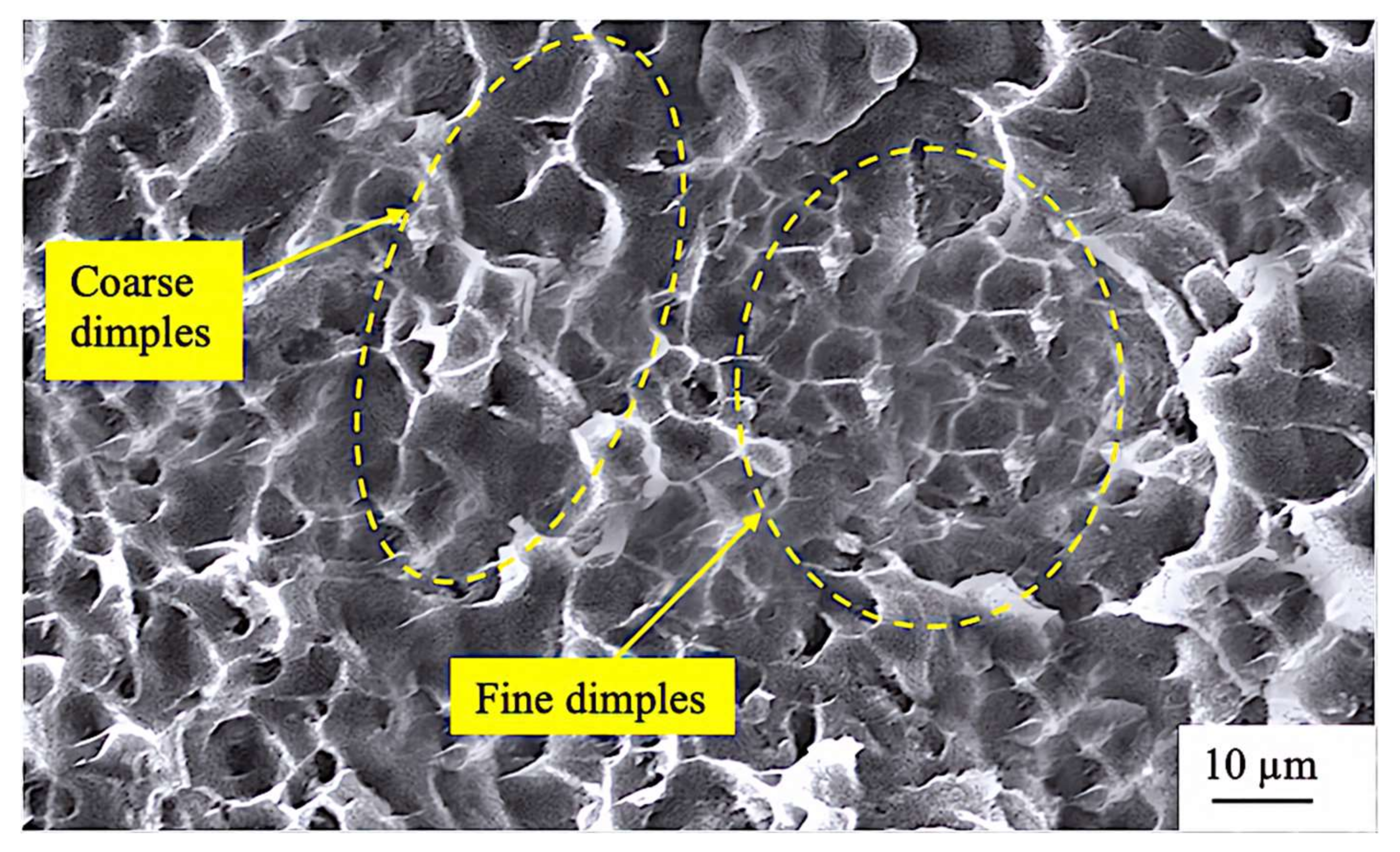
- Fractography revealed mostly fine dimples, with a few coarse dimples also visible.
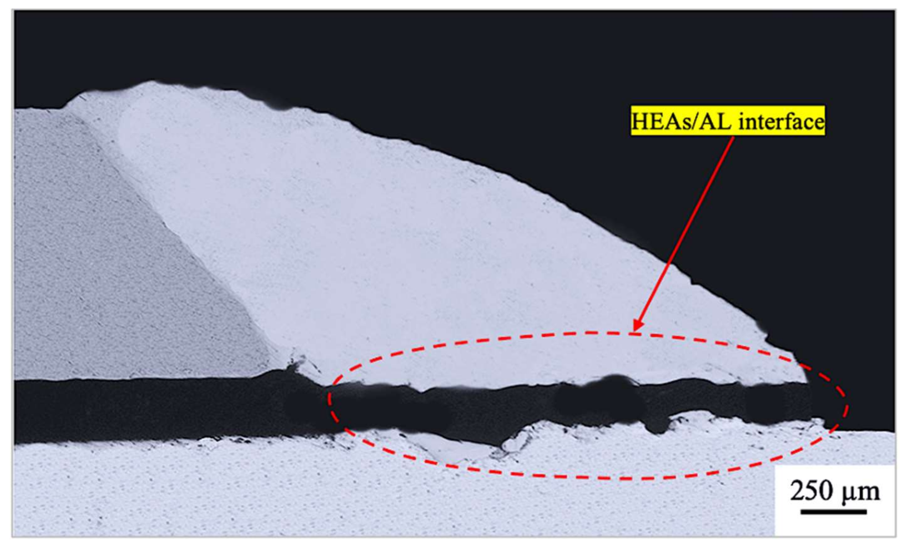
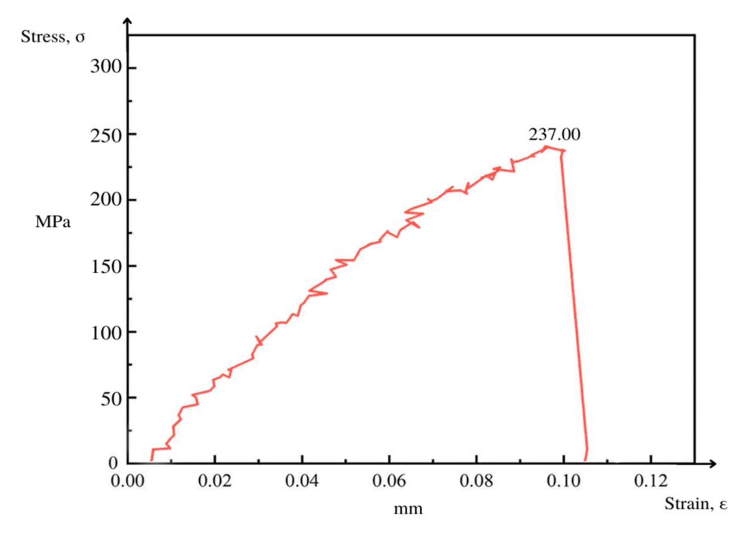
- The weld had a tensile strength of 237 MPa, and the tensile fracture was prolonged at the joint’s HEAs/Al metal interface.
- The highest microhardness achieved in the weld zone was at the HEAs/Fe interaction area, which was 703 HV, with the HEAs/ Al weld interface having a microhardness of 207 HV.
Author Contributions
Funding
Institutional Review Board Statement
Informed Consent Statement
Data Availability Statement
Acknowledgments
Conflicts of Interest
References
- Pańcikiewicz, K.; Świerczyńska, A.; Hućko, P.; Tumidajewicz, M. Laser Dissimilar Welding of AISI 430F and AISI 304 Stainless Steels. Materials 2020, 13, 4540. [Google Scholar] [CrossRef] [PubMed]
- Landowski, M.; Świerczyńska, A.; Rogalski, G.; Fydrych, D. Autogenous Fiber Laser Welding of 316L Austenitic and 2304 Lean Duplex Stainless Steels. Materials 2020, 13, 2930. [Google Scholar] [CrossRef] [PubMed]
- Lin, C.; Shiue, R.-K.; Wu, S.-K.; Huang, H.-L. Infrared Brazing of CoCrFeMnNi Equiatomic High Entropy Alloy Using Nickel-Based Braze Alloys. Entropy 2019, 21, 283. [Google Scholar] [CrossRef] [PubMed]
- Jiang, P.; Chen, R. Research on Interfactial Layer of Laser-Welded Aluminum to Titanium. Mater. Charact. 2019, 154, 264–268. [Google Scholar] [CrossRef]
- Borrisutthekul, R.; Yachi, T.; Miyashita, Y.; Mutoh, Y. Suppression of Intermetallic Reaction Layer Formation by Controlling Heat Flow in Dissimilar Joining of Steel and Aluminum Alloy. Mater. Sci. Eng. A 2007, 467, 108–113. [Google Scholar] [CrossRef]
- Bouche, K.; Barbier, F.; Coulet, A. Intermetallic Compound Layer Growth Between Solid Iron and Molten Aluminium. Mater. Sci. Eng. A 1998, 249, 167–175. [Google Scholar] [CrossRef]
- Colegrove, P.; Williams, S.W.; Ikeagu, C.; Thistlethwaite, A. The Impact of Different Types of Welding Processes on the Residual Stress and Distortion in 4 mm Thick Butt Welds of Ship Plate. In Trends in Welding Research: Proceedings of the 8th International Conference. ASM International Georgia, USA; David, S.A., DebRoy, T., DuPont, J.N., Koseki, T., Smartt, H.B., Eds.; ASM International: Materials Park, OH, USA, 2009; pp. 758–765. [Google Scholar]
- He, Z.; Sun, L.; Li, C.; Si, X.; Zhang, C.; Qi, J.; Feng, J.; Cao, J. Wetting and Brazing of Cf/C Composite with Si–Zr Eutectic Alloy: The formation of nano-and coarse-SiC reaction layers. Carbon 2020, 167, 92–103. [Google Scholar] [CrossRef]
- Ding, J.; Colegrove, P.; Mehnen, J.; Ganguly, S.; Almeida, P.M.S.; Wang, F.; Williams, S. Thermo-mechanical Analysis of Wire and Arc Additive Layer Manufacturing Process on Large Multi-layer Parts. Comput. Mater. Sci. 2011, 50, 3315–3322. [Google Scholar] [CrossRef]
- Górka, J. Assessment of the Effect of Laser Welding on the Properties and Structure of TMCP Steel Butt Joints. Materials 2020, 13, 1312. [Google Scholar] [CrossRef]
- Lisiecki, A.; Ślizak, D. Hybrid Laser Deposition of Composite WC-Ni Layers with Forced Local Cryogenic Cooling. Materials 2021, 14, 4312. [Google Scholar] [CrossRef]
- Kotarska, A.; Poloczek, T.; Janicki, D. Characterization of the Structure, Mechanical Properties and Erosive Resistance of the Laser Cladded Inconel 625-Based Coatings Reinforced by TiC Particles. Materials 2021, 14, 2225. [Google Scholar] [CrossRef] [PubMed]
- Kik, T. Heat Source Models in Numerical Simulations of Laser Welding. Materials 2020, 13, 2653. [Google Scholar] [CrossRef] [PubMed]
- Lubas, J.; Szczypiński-Sala, W.; Woś, P.; Zielińska, E.; Miernik, K. Experimental Analysis of Tribological Processes in Friction Pairs with Laser Borided Elements Lubricated with Engine Oils. Materials 2020, 13, 5810. [Google Scholar] [CrossRef] [PubMed]
- Luo, Y.; Jiang, W.; Zhang, W.; Zhang, Y.; Woo, W.; Tu, S. Notch effect on creep damage for Hastelloy C276-BNi2 brazing joint. Mater. Des. 2015, 84, 212–222. [Google Scholar] [CrossRef]
- Fan, J.; Thomy, C.; Vollertsen, F. Effect of Thermal Cycle on the Formation of Intermetallic Compounds in Laser Welding of Aluminum-Steel Overlap Joints. Phys. Proced. 2011, 12, 134–141. [Google Scholar] [CrossRef]
- Urbańczyk, M.; Adamiec, J. Hybrid Welding (Laser–Electric Arc MAG) of High Yield Point Steel S960QL. Materials 2021, 14, 5447. [Google Scholar] [CrossRef]
- Czupryński, A. Comparison of Properties of Hardfaced Layers Made by a Metal-Core-Covered Tubular Electrode with a Special Chemical Composition. Materials 2020, 13, 5445. [Google Scholar] [CrossRef]
- Walczak, M.; Szala, M. Effect of Shot Peening on the Surface Properties, Corrosion and Wear Performance of 17-4PH Steel Produced by DMLS Additive Manufacturing. Archiv. Civ. Mech. Eng. 2021, 21, 157. [Google Scholar] [CrossRef]
- Rahman Rashid, R.A.; Nazari, K.A.; Barr, C.; Palanisamy, S.; Orchowski, N.; Matthews, N.; Dargusch, M.S. Effect of Laser Reheat Post-treatment on the Microstructural Characteristics of Laser-Cladded Ultra-High Strength Steel. Surf. Coat. Technol. 2019, 372, 93–102. [Google Scholar] [CrossRef]
- Majkowska-Marzec, B.; Tęczar, P.; Bartmański, M.; Bartosewicz, B.; Jankiewicz, B.J. Mechanical and Corrosion Properties of Laser Surface-Treated Ti13Nb13Zr Alloy with MWCNTs Coatings. Materials 2020, 13, 3991. [Google Scholar] [CrossRef]
- Jażdżewska, M.; Kwidzińska, D.B.; Seyda, W.; Fydrych, D.; Zieliński, A. Mechanical Properties and Residual Stress Measurements of Grade IV Titanium and Ti-6Al-4V and Ti-13Nb-13Zr Titanium Alloys after Laser Treatment. Materials 2021, 14, 6316. [Google Scholar] [CrossRef] [PubMed]
- Fu, Y.; Guo, N.; Zhou, C.; Wang, G.; Feng, J. Investigation on In-situ Laser Cladding Coating of the 304 Stainless Steel in Water Environment. J. Mater. Process. Technol. 2021, 289, 116849. [Google Scholar] [CrossRef]
- Hwang, T.W.; Han, S.W.; Lee, T.; Kim, J.H.; Van Tyne, C.J.; Moon, Y.H. Underwater Surface Remelting of Selective Laser Melted Titanium Parts. J. Mater. Res. Technol. 2020, 9, 10447–10458. [Google Scholar] [CrossRef]
- Kim, D.; Badarinarayan, H.; Kim, J.H.; Kim, C.; Okamoto, K.; Wagoner, R.H.; Chung, K. Numerical Simulation of Friction Stir Butt Welding Process for AA5083-H18 Sheets. Eur. J. Mech. A Solids 2010, 29, 204–215. [Google Scholar] [CrossRef]
- Olson, D.L. ASM Handbook Volume 6: Welding, Brazing and Soldering; ASM International: Cleveland, OH, USA, 1993; p. 2603. [Google Scholar]
- Danielewski, H.; Skrzypczyk, A. Steel Sheets Laser Lap Joint Welding—Process Analysis. Materials 2020, 13, 2258. [Google Scholar] [CrossRef]
- Ma, J.; Harooni, M.; Carlson, B.; Kovacevic, R. Dissimilar Joining of Galvanized High-strength Steel to Aluminum Alloy in a Zero-gap Lap Joint Configuration by Two-pass Laser Welding. Mater. Des. 2014, 58, 390–401. [Google Scholar] [CrossRef]
- Liu, H.; Xin, C.; Liu, L.; Zhuang, C. Effects of Different Contents of Each Component on the Structural Stability and Mechanical Properties of Co-Cr-Fe-Ni High-Entropy Alloys. Appl. Sci. 2021, 11, 2832. [Google Scholar] [CrossRef]
- Zhu, J.; Fu, H.; Zhang, H.; Wang, A.; Li, H.; Hu, Z. Microstructure and Compressive Properties of Multiprincipal Component AlCoCrFeNiCx Alloys. J. Alloys Compd. 2011, 509, 3476–3480. [Google Scholar] [CrossRef]
- Yeh, J.W. Alloy Design Strategies and Future Trends in High-Entropy Alloys. JOM 2013, 65, 1759–1771. [Google Scholar] [CrossRef]
- Mathieu, A.; Shabadi, R.; Deschamps, A.; Suery, M.; Matteı, S.; Grevey, D.; Cicala, E. Dissimilar Material Joining Using Laser (Aluminum to Steel using Zinc-based Filler Wire). Opt. Laser Technol. 2007, 39, 652–661. [Google Scholar] [CrossRef]
- Cantor, B. Multicomponent and High Entropy Alloys. Entropy 2014, 16, 4749. [Google Scholar] [CrossRef]
- Meco, S.; Ganguly, S.; Williams, S.; McPherson, N. Effect of Laser Processing Parameters on the Formation of Intermetallic Compounds in Fe-Al Dissimilar Welding. J. Mater. Eng. Perform. 2014, 23, 3361–3370. [Google Scholar] [CrossRef]
- Ozaki, H.; Kutsuna, M. Laser-roll Welding of a Dissimilar Metal Joint of Low Carbon Steel to Aluminium Alloy Using 2 kW Fibre Laser. Weld. Int. 2009, 23, 345–352. [Google Scholar] [CrossRef]
- Quintino, L.; Assunção, E. Conduction laser welding. In Handbook of Laser Welding Technologies; Katayama, S., Ed.; Woodhead Publishing: Sawston, UK, 2013; pp. 139–162. [Google Scholar] [CrossRef]
- Schubert, E.; Zerner, I.; Sepold, G. Laser beam joining of material combinations for automotive applications. Lasers Mater. Process. 1997, 3097, 212–221. [Google Scholar] [CrossRef]
- Shahverdi, H.R.; Ghomashchi, M.R.; Shabestari, S.; Hejazi, J. Microstructural Analysis of Interfacial Reaction between Molten Aluminium and Solid Iron. J. Mater. Process. Technol. 2002, 124, 345–352. [Google Scholar] [CrossRef]
- Vemanaboina, H.; Gundabattini, E.; Akella, S.; Rao, A.C.U.M.; Buddu, R.K.; Ferro, P.; Berto, F. Mechanical and Metallurgical Properties of CO2 Laser Beam INCONEL 625 Welded Joints. Appl. Sci. 2021, 11, 7002. [Google Scholar] [CrossRef]
- Chludzinski, M.; dos Santos, R.E.; Churiaque, C.; Ortega-Iguña, M.; Sánchez-Amaya, J.M. Pulsed Laser Welding Applied to Metallic Materials—A Material Approach. Metals 2021, 11, 640. [Google Scholar] [CrossRef]
- Lopes, J.G.; Oliveira, J.P. A Short Review on Welding and Joining of High Entropy Alloys. Metals 2020, 10, 212. [Google Scholar] [CrossRef]
- Pereira, A.B.; Cabrinha, A.; Rocha, F.; Marques, P.; Fernandes, F.A.O.; Alves de Sousa, R.J. Dissimilar Metals Laser Welding between DP1000 Steel and Aluminum Alloy 1050. Metals 2019, 9, 102. [Google Scholar] [CrossRef]
- Springer, H.; Kostka, A.; Payton, E.J.; Raabe, D.; Kaysser-Pyzalla, A.; Eggeler, G. On the formation and growth of intermetallic phases during interdiffusion between lowcarbon steel and aluminum alloys. Acta Mater. 2011, 59, 1586–1600. [Google Scholar] [CrossRef]
- Mohan, D.G.; Tomków, J.; Gopi, S. Induction Assisted Hybrid Friction Stir Welding of Dissimilar MaterialsAA5052 Aluminium Alloy and X12Cr13 Stainless Steel. Adv. Mater. Sci. 2021, 21, 17–30. [Google Scholar] [CrossRef]
- Suder, W.J.; Williams, S.W. Investigation of the Effects of Basic Laser Material Interaction Parameters in Laser Welding. J. Laser Appl. 2012, 24, 032009. [Google Scholar] [CrossRef]
- Wang, X.; Wood, J.V.; Sui, Y.; Lu, H. Formation of Intermetallic Compound in Ironaluminum Alloys. J. Shanghai Univ. (Engl. Ed.) 1998, 2, 305–310. [Google Scholar] [CrossRef]
- AnandhaKumar, C.J.; Gopi, S.; Mohan, D.G.; ShashiKumar, S. Predicting the Ultimate Tensile Strength and Wear Rate of Aluminium Hybrid Surface Composites Fabricated via Friction Stir Processing Using Computational Methods. J. Adhes. Sci. Technol. 2021, 1–20. [Google Scholar] [CrossRef]
- Bi, J.; Lei, Z.; Chen, Y.; Chen, X.; Tian, Z.; Liang, J.; Qin, X.; Zhang, X. Densification, Microstructure and Mechanical Properties of an Al-14.1Mg-0.47Si-0.31Sc-0.17Zr Alloy Printed by Selective Laser Melting. Mater. Sci. Eng. A 2020, 774, 138931. [Google Scholar] [CrossRef]
- Zhu, Z.; Wang, W.; Li, Y.; Chen, H. Effect of Laser-arc Offset and Laser-deviation Angle on the Control of a Ti-Al Interlayer. J. Mater. Process. Technol. 2019, 271, 336–345. [Google Scholar] [CrossRef]
- Way, M.; Luo, D.; Tuley, R.; Goodall, R. A new High Entropy Alloy Brazing Filler Metal Design for Joining Skutterudite Thermoelectrics to Copper. J. Alloys Compd. 2020, 858, 157750. [Google Scholar] [CrossRef]
- Mohan, D.G.; Gopi, S.; Tomków, J.; Memon, S. Assessment of Corrosive Behaviour and Microstructure Characterization of Hybrid Friction Stir Welded Martensitic Stainless Steel. Adv. Mater. Sci. 2021, 21, 67–78. [Google Scholar] [CrossRef]
- Cao, J.; Zhang, L.; Wang, H.; Wu, L.; Feng, J. Effect of Silver Content on Microstructure and Properties of Brass/steel Induction Brazing Joint Using Ag-Cu-Zn-Sn Filler Metal. J. Mater. Sci. Technol. 2011, 27, 377–381. [Google Scholar] [CrossRef]
- Quazi, M.M.; Ishak, M.; Fazal, M.A.; Arslan, A.; Rubaiee, S.; Qaban, A.; Aiman, M.H.; Sultan, T.; Ali, M.M.; Manladan, S.M. Current research and development status of dissimilar materials laser welding of titanium and its alloys. Opt. Laser Technol. 2020, 126, 106090. [Google Scholar] [CrossRef]
- Tomashchuk, I.; Sallamand, P.; Measson, A.; Cicala, E.; Duband, M.; Peyre, P.J. Aluminum to Titanium Laser Welding-brazing in V-shaped Groove. Mater. Process. Technol. 2017, 245, 24–36. [Google Scholar] [CrossRef]
- Song, Z.; Nakata, K.; Wu, A.; Liao, J. Interfacial Microstructure and Mechanical Property of Ti6Al4V/A6061 Dissimilar Joint by Direct Laser Brazing without Filler Metal and Groove. Mater. Sci. Eng. A 2013, 560, 111–120. [Google Scholar] [CrossRef]
- Glowka, K.; Zubko, M.; Świec, P.; Prusik, K.; Szklarska, M.; Chrobak, D.; Lábár, J.L.; Stróż, D. Influence of Molybdenum on the Microstructure, Mechanical Properties and Corrosion Resistance of Ti20Ta20Nb20(ZrHf)20−xMox (Where: x = 0, 5, 10, 15, 20) High Entropy Alloys. Materials 2022, 15, 393. [Google Scholar] [CrossRef] [PubMed]
- Sharma, A. High-Entropy Alloys for Micro- and Nanojoining Applications. In Engineering Steels and High Entropy-Alloys; IntechOpen: London, UK, 2020. [Google Scholar]
- Mohan, D.G.; Gopi, S. Influence of In-situ Induction Heated Friction Stir Welding on Tensile, Microhardness, Corrosion Resistance and Microstructural Properties of Martensitic Steel. Eng. Res. Express 2021, 3, 25023. [Google Scholar] [CrossRef]
- Tomashchuk, I.; Sallamand, P.; Cicala, E.; Peyre, P.; Grevey, D. Direct Keyhole Laser Welding of Aluminum Alloy AA5754 to Titanium Alloy Ti6Al4V. J. Mater. Process. Technol. 2015, 217, 96–104. [Google Scholar] [CrossRef]
- Chen, S.-H.; Li, L.-Q.; Chen, Y.-B.; Liu, D.-J. Si Diffusion Behavior During Laser Welding-brazing of Al alloy and Ti Alloy with Al-12Si Filler Wire. Trans. Nonferrous Met. Soc. China 2010, 20, 64–70. [Google Scholar] [CrossRef]
- Menci, G.; Demir, A.G.; Waugh, D.G.; Lawrence, J.; Previtali, B. Laser Surface Texturing of β-Ti alloy for Orthopaedics: Effect of Different Wavelengths and Pulse Durations. Appl. Surf. Sci. 2019, 489, 175–186. [Google Scholar] [CrossRef]
- Liaw, P.K.; Li, W. High Entropy Materials: Challenges and Prospects. Metals 2021, 11, 1643. [Google Scholar] [CrossRef]
- Hardwick, L.; Rodgers, P.; Pickering, E. Development of Novel Nickel-based Brazing Alloys, Utilisingutilising Alternative Melting Point Depressants and High Entropy Alloy Concepts. In Proceedings of the 12th International Conference on Brazing, High Temperature Brazing and Diffusion Bonding, Aachen, Germany, 21–23 May 2019. [Google Scholar]
- Zhang, Y.; Sun, D.Q.; Gu, X.Y.; Duan, Z.Z.; Li, H.M. Nd:YAG Pulsed Laser Welding of TC4 Ti alloy to 301L Stainless Steel using Ta/V/Fe Composite Interlayer. Mater. Lett. 2018, 212, 54–57. [Google Scholar] [CrossRef]
- Meraj, M.; Pal, S. Deformation of Ni20W20Cu20Fe20Mo20 High Entropy Alloy for Tensile followed by Compressive and Compressive followed by Tensile Loading: A Molecular Dynamics Simulation Based Study. IOP Conf. Ser. Mater. Sci. Eng. 2019, 115, 012019. [Google Scholar] [CrossRef]
- Luo, D.; Xiao, Y.; Hardwick, L.; Snell, R.; Way, M.; Sanuy Morell, X.; Livera, F.; Ludford, N.; Panwisawas, C.; Dong, H.; et al. High Entropy Alloys as Filler Metals for Joining. Entropy 2021, 23, 78. [Google Scholar] [CrossRef] [PubMed]
- Liu, D.; Wang, J.; Xu, M.; Jiao, H.; Tang, Y.; Li, D.; Zhao, L.; Han, S. Evaluation of Dissimilar Metal Joining of Aluminum Alloy to Stainless Steel using the Filler Metals with a High-entropy Design. J. Manuf. Process. 2020, 58, 500–509. [Google Scholar] [CrossRef]
- Fu, A.; Cao, Y.; Liu, Y.; Xu, S. Microstructure and Mechanical Properties of Novel Lightweight TaNbVTi-Based Refractory High Entropy Alloys. Materials 2022, 15, 355. [Google Scholar] [CrossRef] [PubMed]
- Meng, F.S.; Yao, Z.; Všianská, M.; Friák, M.; Šob, M. Theoretical Investigations on Structural, Elastic, Thermodynamic and Electronic Properties of Al3Ti and Al3V Compounds in L12 Structure under High Pressure. Mater. Res. Express 2019, 6, 056536. [Google Scholar] [CrossRef]


| Material | Tensile Strength [MPa] | Elongation [%] | Hardness [HV] |
|---|---|---|---|
| UNS S33207 | 970 | 25 | 523 |
| AA 6061 | 210 | 18 | 107 |
| Material | C | Cr | Ni | Mo | Mn | Cu | Co | Si | N | Al | O | Fe |
|---|---|---|---|---|---|---|---|---|---|---|---|---|
| UNS S33207 | 0.03 | 26.13 | 6.31 | 4.72 | 1.25 | 1.02 | 0.97 | 0.49 | 0.38 | 0.02 | 0.015 | Remaining |
| Mg | Si | Fe | Cu | Mn | Zn | Ti | Al | |||||
| AA 6061 | 0.92 | 0.71 | 0.34 | 0.30 | 0.16 | 0.02 | 0.01 | Remaining | ||||
| Area | Composition in Weight% | Related Phases | ||||||
|---|---|---|---|---|---|---|---|---|
| Co | Cu | Ni | Al | Fe | V | Mn | ||
| A (i) | 0.98 | 6.21 | 3.04 | 68.98 | 0.00 | 20.02 | 1.95 | Al3V |
| B (ii) | 12.98 | 19.72 | 14.87 | 0.00 | 0.00 | 29.01 | 18.71 | DCC + V (SS) |
| C (iii) | 11.26 | 11.98 | 17.47 | 0.00 | 12.21 | 29.24 | 19.29 | DCC + V (SS) |
| E (v) | 16.02 | 20.01 | 15.82 | 0.00 | 0.00 | 28.49 | 19.82 | DCC + V (SS) |
| G (vii) | - | - | - | - | - | 98.63 | - | V |
Publisher’s Note: MDPI stays neutral with regard to jurisdictional claims in published maps and institutional affiliations. |
© 2022 by the authors. Licensee MDPI, Basel, Switzerland. This article is an open access article distributed under the terms and conditions of the Creative Commons Attribution (CC BY) license (https://creativecommons.org/licenses/by/4.0/).
Share and Cite
Mohan, D.G.; Tomków, J.; Karganroudi, S.S. RETRACTED: Laser Welding of UNS S33207 Hyper-Duplex Stainless Steel to 6061 Aluminum Alloy Using High Entropy Alloy as a Filler Material. Appl. Sci. 2022, 12, 2849. https://doi.org/10.3390/app12062849
Mohan DG, Tomków J, Karganroudi SS. RETRACTED: Laser Welding of UNS S33207 Hyper-Duplex Stainless Steel to 6061 Aluminum Alloy Using High Entropy Alloy as a Filler Material. Applied Sciences. 2022; 12(6):2849. https://doi.org/10.3390/app12062849
Chicago/Turabian StyleMohan, Dhanesh G., Jacek Tomków, and Sasan Sattarpanah Karganroudi. 2022. "RETRACTED: Laser Welding of UNS S33207 Hyper-Duplex Stainless Steel to 6061 Aluminum Alloy Using High Entropy Alloy as a Filler Material" Applied Sciences 12, no. 6: 2849. https://doi.org/10.3390/app12062849
APA StyleMohan, D. G., Tomków, J., & Karganroudi, S. S. (2022). RETRACTED: Laser Welding of UNS S33207 Hyper-Duplex Stainless Steel to 6061 Aluminum Alloy Using High Entropy Alloy as a Filler Material. Applied Sciences, 12(6), 2849. https://doi.org/10.3390/app12062849