Abstract
This article outlines the merits of the proposed synchronous propulsion and assembly method in the construction of a long-distance tunnel. In traditional shield construction, the stress of the unlooped segment during the assembly process is systematically overlooked. However, in the novel tunnel construction method, the advancing force of the shield directly acts on the unlooped segment, so the safety of the unlooped segment is unknown. In this paper, focusing on the safety of the segment assembly process, the segment interactions and stress concentrations under asymmetric force effects are analysed in detail via a suite of finite element models. The results show that in the synchronous propulsion and assembly mode the segments will rotate inward. A clamping effect will gradually appear during the assembly process, which makes segment deflection decrease and the stress distribution more uniform. Under asymmetrical stress, the damage to longitudinal segments is highly correlated with the types of assembly errors. The damage position that is deflected radially inward will change with the deflection angle, and the outer joint of the segment is the largest. Based on the numerical outputs, guidelines for the application of synchronous propulsion and assembly technology in practical engineering are provided.
1. Introduction
With the development of underground spaces in cities and surrounding areas, the construction of shield tunnels is becoming more and more frequent. However, the development of a regional economy means that the length of the shield tunnel continues to extend. There is an urgent need to change the traditional construction technology to adapt to the rapid growth of tunnel demand. In terms of improving tunnel construction speed, this mainly depends on: (i) improving the shield tunneling speed; and (ii) simultaneous shield propulsion and segment assembly, i.e., synchronous propulsion and assembly technology. In the case of normal shield construction, the shield stops advancing. After the segments are assembled into rings, the hydraulic jack propels the newly assembled assembly ring to provide the support of the tunnel surface and the thrust of the shield. In the synchronous propulsion and assembly mode, the shield does not need to stop, and the jack acts directly on the unlooped segments to propel while assembling. The synchronous propulsion and assembly technology systematically reduces the suspension time during tunnel segment assembly [1]. As we all know, the shield propulsion force is borne by the lining ring during the construction of the traditional shield method, and the impact of shield propulsion on the lining ring does not need to be considered during the assembly process of the segment. The new construction method exposes the segments to propulsion loads before they are looped, which puts the segments at greater risk of damage [2,3,4,5]. It is necessary to study the safety of this construction method to ensure the smooth progress of construction.
In fact, the load and working state of shield tunnel segments in the construction stage are complex and uncertain [6]. Focusing on the engineering situation, many scholars have conducted in-depth research on segment damage caused by assembly error in the construction stage. The main research method involves using the integral design models, such as homogeneous ring, elastic hinge ring, and multi-hinge angle ring models. Chen Junsheng studied the concrete cracks detected at different locations [7]. Combined with finite element model analysis, it was shown that the shield machine and segment had an influence in terms of an inclined and uneven jacking load on the assembly quality of the segment. The Japanese Society of Civil Engineers statistically studied the damage frequency of segments in 50 tunnel sites during construction [8]. Tsumoto found that the damage types of segments focused on longitudinal cracks and corner spalling before or during shield propulsion. SHP Cavalaro studied the causes of the above damage. The results show that when a jack is loaded, the longitudinal dislocation of the upper ring can easily cause a longitudinal crack in the next ring segment, and the collision and extrusion of the adjacent segments of the current ring are important causes of corner damage [9].
In addition to the direct relationship between assembly errors in segments and the damage of segments, the excessive vertical loadings caused by jacks during shield propulsion are also an important reason for segment cracking (prefabricated structures), spalling, and water leakage [10,11,12,13]. In the construction process, due to the deformation and contraction of the segment or the low surface smoothness of the segment, the uneven support or load eccentricity in the construction process will further deepen the cracking of the segment [14]. Xu Guowen’s research shows that segment torsion produces additional shear stress when the segment is supported unevenly, which causes oblique cracks. Under the action of axial thrust, the pipe section appears in the compression and tensile stress area, and longitudinal cracks may appear near the vault, inverted arch, and waist [15]. Saleta Gil Lorenzo carried out a detailed study on the situation of segments subjected to radial force. Under symmetric radial force, a newly assembled tube deflects radially around the previously assembled tube [16]. When subjected to asymmetric radial force, the hoop tension at the inversion increases locally [17]. The circumferential torque is caused by the radial component of the reaction force of the pad in the fixed section or by the gradual adoption of an ellipse facing the back of the R1 ring. The difference of ring deformation between the front and back of the segment will lead to serious torsion.
When the lining is subjected to continuous radial load, the lining ring will appear ‘tulip’-shaped, that is, the diameter of the front end of the lining will be larger than the uneven shape of the compressed area at the back end [18,19,20]. This ‘tulip’ shape will cause contact defects on the bearing surface of the longitudinal joint, and plastic deformation will occur in the compression zone, which may even cause permanent damage to some tunnel linings. With the lining out of the shield tail, the tunnel segment will gradually show horizontal diameter increase and vertical diameter decrease in the self-weight stage of the segment, and the overall shape will resemble a duck egg; this has a serious impact on the force of the segment. At the same time, the lining of the tulip shape is a huge challenge [21,22].
Nowadays, a large number of studies focus on the performance of lining structures under different loads. The purpose is to understand the stress response and cracking mechanism of linings under different external concentrated loads. Usually, loads are applied on segments with different positions and shapes through large-scale bench tests, full-scale tests, field measurements, and finite element numerical modelling [23,24,25,26,27,28]. Some scholars have also introduced assembly tolerance and penalty functions, and the principle of minimum potential energy is applied to study the analytical solution of segment internal force considering the pre-deformation and inaccuracy of lining segments [29]. The segment structure based on the traditional shield construction method is studied in detail. Most of the research objects are complete lining rings and segment structures with constraints on both sides.
However, with the development of shield construction technology, the stress of traditional shield linings is completely different from that of segments under synchronous propulsion and assembly technology. First, the absence of the hoop effect on both sides of a newly assembled segment allows the segment to have a higher degree of freedom when advancing. Second, compared with the traditional shield method, the newly assembled segments will bear the jack thrust directly during propulsion under the synchronous propulsion and assembly mode. Third, when there is an assembly error or the jack is inclined, this will greatly affect the ultimate load of the segment. There is also the technical difficulty relating to synchronous propulsion and assembly technology which needs to be overcome urgently.
Based on the background of synchronous propulsion and assembly technology, this paper studies the structural response of segments in different assembling positions and under the condition of asymmetrical propulsion exerted by jacks. By establishing a finite element model of segment assembly, we explore the interaction and stress concentration of unlooped segments under asymmetric stress in the synchronous propulsion and assembly mode. This study determines the assembly error control range of the synchronous propulsion and assembly mode applied in practical projects. The theoretical basis and technical reference are established to warrant future synchronous propulsion and assembly projects.
2. Project Overview and the Synchronous Propulsion and Assembly Method
2.1. Project Overview
The airport connecting line (west section) project of the Shanghai rail transit city line is the trunk line connecting Shanghai’s international airports. The tunnel runs east–west as a whole, with a total length of about 68.6 km, including an underground section of 56.7 km. The maximum overburden of the tunnel top is 33 m, the minimum is 14 m, the minimum radius is R520, the maximum longitudinal slope is 2%, and the length below the radius of R600 is about 660 m. The construction sequence of the tunnel is shown by the red arrow in Figure 1. The main crossing strata are ④ Silt clay, ⑤1 silty clay, ⑥1 silty clay, and ⑦1 silty sand mixed with silty clay. The specific soil layer structure is shown in Figure 1.
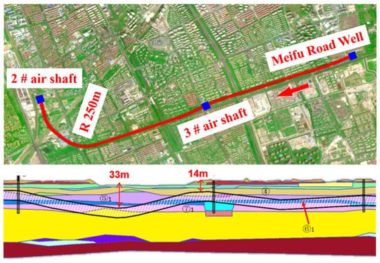
Figure 1.
Longitudinal profile of excavation soil layer in synchronous propulsion and assembly mode.
The outer diameter of the tunnel lining ring is Φ13.6 m, the inner diameter is Φ12.5 m, and the thickness of the segment is 550 mm. The lining adopts a universal wedge-shaped ring, in the form of a 6 + 2 + 1 (1/2) block, which consists of six standard segments, two adjacent segments, and one capping block. The average length of the lining ring is about 2 m. The segment is made of high-performance concrete with a strength of C60 and an impermeability grade of P12. Taking the standard block as an example, the outer side of the segment contact surface is wrapped with an elastic gasket covering 42.352°. The inner side of the contact surface of the segment is covered with a packer, and the packer coverage angle is 40°. Each standard block is directly loaded by four jacks, and the contact area between the jack and the segment is protected by a shoe plate.
2.2. Synchronous Propulsion and Assembly Method
Based on the above engineering requirements, the synchronous propulsion and assembly technology is proposed in the hope that it will reduce the impact of long tunnel distances on construction periods. The synchronous propulsion and assembly technology is mainly used in the straight-line section of Meifu Road Well to 3# air shaft construction. The synchronous propulsion and assembly technology is adopted under the condition of suitable geology, as shown in Figure 2.
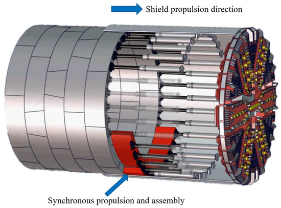
Figure 2.
Schematic diagram of the synchronous propulsion and assembly method.
Synchronous propulsion and assembly method is realized by intelligently controlling the pressure of the shield propelling cylinder. The difference with respect to the traditional shield is that the shield machine of the synchronous propulsion and assembly method lengthens the length of the jacking cylinder and realizes the synchronous assembly of some segments by using the surplus of the stroke of the push cylinder. The construction efficiency of the synchronous propulsion and assembly method is directly proportional to the remaining distance of the jack, which can shorten the construction time of each ring segment by 60% at most. The shield machine used in this project has a margin time for the assembly of three segments. Therefore, the focus of this paper is also on the stress of the three segments in the synchronous propulsion and assembly mode. The specific operation methods of the synchronous propulsion and assembly method are as follows:
- (a)
- The first segment is assembled, the jack acting on the first segment shrinks, and the thrust of the jack smoothly transitions to the thrust of the corresponding working condition;
- (b)
- The assembly of the first segment is completed; the jack acting on the first segment is advanced. The second segment is retracted corresponding to the jack, and the thrust of the jack smoothly transitions to the thrust of the corresponding working condition.
The above working conditions are to be continuously cycled until the assembly of three segments is completed, as shown in Figure 3. During construction, the shield machine will switch to the synchronous propulsion and assembly mode. The contraction of the jack and the setting of the thrust will be automatically carried out by the shield machine. Different from traditional shield propulsion, in the synchronous propulsion and assembly mode, the jack propulsion force will be reasonably distributed to the non-assembled segments.
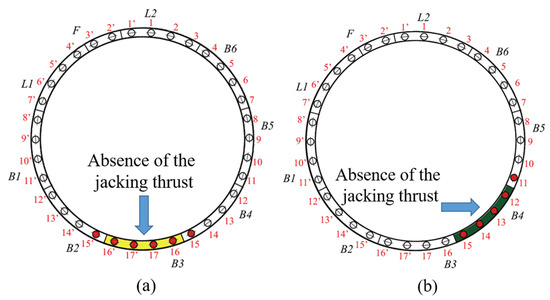
Figure 3.
Steps of jack jacking in synchronous propulsion and assembly mode: (a) The working condition of the jack when the first segment is assembled; (b) The working condition of the jack when the second segment is assembled.
3. Research Methods and Parameters
The segment in the assembly has a certain asymmetry, which is mainly reflected in two aspects: (i) the asymmetry caused by the segment structure at different positions; (ii) stress asymmetry caused by the inclination of the external load direction. In the synchronous propulsion and assembly mode, the assembly state of the assembled segment in the asymmetric state has certain unknowns. Therefore, it is urgent to understand the stress effect of the segment during the assembly process under the condition of asymmetric position, and given that force may be asymmetric, the contact quality between segments is also one of the key subjects of this paper.
By establishing a numerical analysis of the actual engineering segment, the stress response and damage to the tunnel segment in the synchronous propulsion and assembly mode are determined. Based on the assembly sequence of the three segments, the segment assembly model is established, and different assembly errors are introduced when assembling segments. The solid model of segment, packer, and elastic gasket is established by finite element software, and the damage to the segment is described by a concrete elastoplastic damage constitutive model.
3.1. General Description of the Models
The tunnel segment model is established based on the airport connecting line (west section) project of the Shanghai metro line, as shown in Figure 4. The study focuses on the stress between the assembled segment and the completed lining, so the model can be simplified as the interactive simulation of the assembled segment and the adjacent ring contact segment. Some minor details are ignored in modellings, such as bolt holes, wedges of segments, grooves, and bolts. Setting springs between the newly assembled segments simulates the role of bolts between segments. In the assembly, the default assembled segments experience no assembly errors, and the assembly of the segments will follow the longitudinal seam bonding principle, that is, default perfect bonding between adjacent segments of the same ring segment. The geometric parameters and mesh properties of the segment are shown in Table 1 and Table 2.
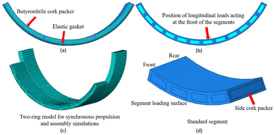
Figure 4.
Geometry and mesh of finite element models: (a) The location of the butyronitrile cork packer and elastic gasket; (b) Position of longitudinal loads acting; (c) Mesh of standard segments; (d) Description of segment orientation.

Table 1.
Input geometrical parameters for the finite element models.
Table 2.
Mesh properties for the FE modelling.
The segments, packers, and gaskets are modeled with first-order hexahedral elements, which can reduce the calculation time of the 3D numerical model and ensure the accuracy of the model calculation. To reflect the inelastic behavior of concrete, the finite element software adopts the isotropic elastic damage and tensile-compression plasticity theory. In order to show the elastic-plastic results of concrete under compression, the isotropic elastic damage and tensile-compression plasticity theory are used in the model. The Mooney–Rivlin strain potential energy model [30,31] is used for the gasket and packer. The physical parameters of the materials are shown in Table 3.
Table 3.
Constitutive parameters for the finite element models.
When the jack acts on the segment, the segment has been fixed at the assembly position by the robotic arm, and the gasket contacts with the adjacent segment. In the simulation, the default gasket will not have relative displacement, and the gasket is fixed with two adjacent segments by binding. The hard contact relationship is adopted between the assembled segments to minimize the relative positional movement between them. One side of the packer is bound to the new assembly ring. The penalty function is used to simulate the finite sliding of circumferential gasket–segment and segment–segment surface contact. Based on the shear stiffness test of the circular tunnel joint [32], the friction coefficient between fine concrete and liner can be taken as 0.5.
3.2. Loading and Boundary Conditions
During the assembly process of the segment, the position of the first segment will form a periodic rotation due to the wedge shape of the segment itself, which is the main reason for the position asymmetry. The propulsion force of the synchronous propulsion and assembly mode will increase in gradient with different depths, so different boundary conditions and constraints need to be set for segments at different positions. According to the actual engineering situation, three models were established to simulate the assembly process of the three segments. Gravity is introduced in the assembly, and the different positions of the segments are simulated by setting different directions of gravity.
In the synchronous propulsion and assembly mode, the external loads borne by the segment during the assembly process are the thrust of the jack and its gravity. The main reaction of the asymmetric force of the segment is the angle error formed between the segment and the jack, as shown in Figure 5. The main reasons for this are the assembly error of the segment and the angle formed by the shield and the segment during the construction process. In this paper, it is assumed that the initial position of the segment is suspended in parallel with the segment that has been looped, and the assembly error is transformed into the radial and tangential components of the jack. The deflection error range of the segment in the study mainly refers to the maximum assembly error between the shield and the segment and the maximum stroke difference of the shielding jack.
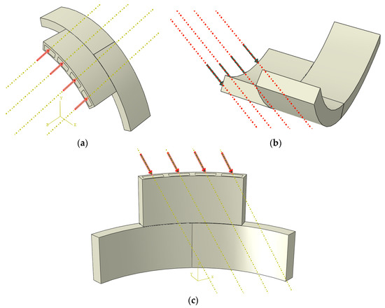
Figure 5.
Assembly error of segment: (a) inward deflection; (b) outward deflection; (c) lateral deflection. (Take the assembly of one segment as an example.)
The assembly process of the segment consists of a series of complex segment–liner–segment interaction processes. Compared with the unassembled segment, the assembled segment will form a hoop effect due to the interaction of the annular structure, and the relative displacement is smaller. In the study, the back push surface of the ringed segment and the two sides of the ringed segment are used as boundaries. The longitudinal displacement of the looped segment is eliminated by applying hinge constraints to the back push surface of the looped segment and both sides of the segment.
3.3. Modelling Sequence
The modeling order of the model changes as the segments are assembled. The assembly sequence of segments is as shown in Figure 6. Taking the third segment assembly model as an example, displacement constraints are first imposed on both sides of the looped segment. The back push surface and the global gravity is activated according to the working conditions to initialize the segment’s positional information. Next, the thrust of the jack on the face of the two segments that have been assembled is activated. Before the radial or tangential component force of the jack is activated, a certain longitudinal thrust is applied to form a certain contact between the gasket and the surface of the ring-shaped segment to reduce the relative slip. To maintain the boundary conditions of the ring segment, the radial or tangential component force of the jack can be added as required. Finally, the jack thrust and error component of the third segment are activated, and the component force is consistent with that of the other two segments. By adjusting the component force of the jack accordingly, the response of the segment under different assembly errors is simulated.
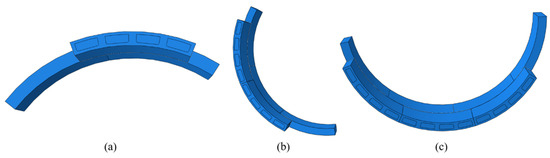
Figure 6.
The assembly sequence of segments: (a) assembly of the first segment (take the segment at the top as an example); (b) assembly of the second segment (take the lateral segment as an example); (c) assembly of the third segment (take the segment at the bottom as an example).
4. Evaluation of Concrete Segment Damage
The damage–plastic constitutive relation of concrete is based on the elastic–plastic constitutive relation of concrete, and the damage factor is introduced. Non-associative hardening was introduced into the elastoplastic constitutive relation of concrete to better simulate the compressive elastoplastic behavior of concrete.
The strength of the super-large diameter shield segment concrete is C60. According to the Code for Design of Concrete Structures GB50010-2002 [33], the compressive stress–strain relationship of the C60 concrete segment is expressed as:
where is the stress in concrete; is the compressive strength of concrete; is the strain in concrete; fcu,k. is the characteristic value of cubic concrete compressive strength; is the strain when reaches ; and is the maximum compressive strain in concrete.
In addition to compressive stress causing surface damage, tensile stress concentration under combined stress is also one of the main reasons for segment failure. Under tensile stress, the crack opening of the segment starts at a critical cohesive traction and ends when a critical opening displacement is attained [34]. The tensile stress–strain relationship of the C60 concrete segment is expressed as:
where is the concrete tensile stress; is the modulus of elasticity of concrete; is the concrete crack width; is the crack width of fully cracked concrete; is the peak tensile stress of concrete; and and are the constants 3 and 6.93, respectively.
Considering the differences in the tensile and compression properties of concrete materials, a damage factor is introduced to describe the reduction of the elastic stiffness matrix of concrete materials under different stress conditions [35,36,37,38]. Based on the compression damage theory of concrete, the damage to a segment is evaluated by the relationship between inelastic strain and the compression damage factor. For tension, the theoretically determined crack width of concrete is the integral of tensile strain to the crack width. Assuming that the crack width is constant, the relationship curve between the crack width and the damage factor can be obtained (Figure 7). The crack width here is based on the average sense.
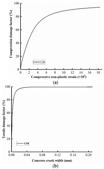
Figure 7.
Damage factor definition curve: (a) compression damage factor; (b) tensile damage factor.
Finally, when the inelastic strain of concrete under compressive failure exceeds 0.002, the compressive strain damage factor is 46% to define the compressive damage of the segment. When the concrete tensile crack width exceeds 0.2 mm, the tensile strain damage factor is 99.61% to define the tensile damage of the segment.
5. Interactions between Segments along the Circumference
During assembly, the attitude of the segment will be deflected under the action of the jack, and the newly assembled segment will have a certain inclination with the previous segment. In addition to the thrust of the jack, the contact quality between the segments will directly have an important influence on the final posture of the segments. When the position of the segment is different, the rotation tendency of the arc segment under different gravity directions is also different. In addition to the posture of the segment, the segment will also have a certain bending deformation for the above-mentioned reasons. This section discusses the interaction results of the segment assembly process in the synchronous propulsion and assembly mode when there is no assembly error. At this time, the segment only bears the gravity and the thrust of the jack. In order to observe the extrusion between segments more intuitively, the deformation cloud map of the model is enlarged 20 times.
5.1. The Segment at the Top
When the initial segment is assembled on top of the tunnel, the segment will rotate inward. The main reason for the rotation of the segments concerns the packer and gaskets between the segments. The jack thrust in the synchronous propulsion and assembly mode will make the segment fit as close to the ring segment as possible, but the unevenness between segments makes the segment and segment contact form a deep beam. It is worth noting that, at this time, the deformation of the inner and outer sides of the packer and the gasket is different, and the inner side is deformed more seriously than the outer side.
When the first segment is assembled, the maximum rotation of the front of the segment is 9 mm, and the front surface rotates greatly as a whole under the action of the jack. At this time, the segment rotates around the two sides of the packer. When the segment is at the top, gravity further increases the inward rotation. When the second segment is assembled, since the support of the segment has been assembled, the rotation of the connecting part of the segment is significantly reduced. There is a certain extrusion between adjacent segments, mainly at the contact of the front of the segment, so the rotation of the free side of the push end of the first segment increases slightly, as shown in Figure 8. The longitudinal seam of the segment presents a small upper seam and a large lower seam. When the third segment is assembled, the rotation of the segment is significantly reduced due to the clamping of the segments on both sides, and the main rotation area is the unconstrained area. It is worth noting that, due to the continuous assembly of the segments, the direction of gravity is not the same. During the assembly process of the second and third segments, the direction of their gravity no longer contributes to the inward deflection of the segments. Compared with the assembly of the first segment, the degree of freedom of the rotation axis of the segment as a whole is constantly changing, so the degree of deflection of the segment is gradually reduced.
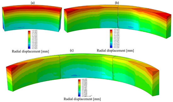
Figure 8.
The interaction between segments when the segments are at the top: (a) first segment assembly; (b) second segment assembly; (c) third segment assembly.
Taking the free side edge of the assembled segment as the starting point, according to the angle, it can be seen that the stress of the front, the rear, and the centreline of the segment at different assembly stages presents different stress distributions (Figure 9a). When the first segment is assembled, the stress of the segment is mainly concentrated at the front and the rear of the segment and the maximum stress is 13 N/mm2. When the segment is at the top, the segment has an obvious tendency to rotate inward, so the stress on the rear of the segment is relatively large. In particular, the stress on both sides of the rear increases rapidly. The main reason is that when the segment rotates, the rotation axis of the segment will autonomously choose to rotate along the edges on both sides of the segment. When the second segment is assembled, one side of the segment is supported by the assembled segment, so the stress at the rear of the segment is significantly reduced. At this time, the transmission of the stress of the segment is affected, and the stress at the front increases slightly. When the third segment is assembled, at least one side of all segments is supported, the stress distribution of segments is relatively uniform, and the overall stress is distributed within 3.5–10.5 N/mm2. The inward rotation of segments is improved. When the third segment is assembled, the middle segment will be squeezed a little, so the stress will surge to a certain extent at the rear and centreline of the segment.
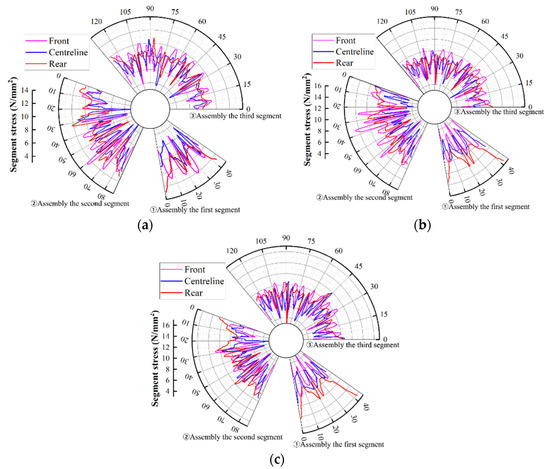
Figure 9.
Internal forces in the model: (a) the segment at the top; (b) the lateral segment; (c) the segment at the bottom.
It can be seen from Figure 10a that the direction and size of the bending moment of the segment are constantly changing due to the assembly of segments. When the first segment is assembled, the bending moment of the segment reaches the maximum at the place where the jack directly acts, and the maximum is 480 kN·m. When the second segment is assembled, the bending direction of the segment changes, and its peak value reaches −590 kN·m. Since the two support each other when they are in contact, the bending moment is lowest at the contact position. When the third segment is assembled, the segments on both sides squeeze the first segment so that the bending direction of the segment is changed. At this time, the bending moment of the third assembled segment is significantly lower than the other two assembled segments, and it is difficult for the two assembled segments to move.
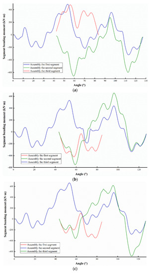
Figure 10.
Bending moment in the model: (a) the segment at the top; (b) the lateral segment; (c) the segment at the bottom.
In short, with the assembly of segments, the maximum bending moment, maximum stress, and displacement of segments are significantly reduced, but there is a certain extrusion in the assembly process. This may mean a risk of damage in the subsequent assembly.
5.2. The Lateral Segment
When the initial assembled segment is lateral, the segment also deflects inward. The difference from the initial segment at the top is that the deflection of the segment is no longer symmetrical, and the symmetry of the segment is destroyed, as shown in Figure 11. When the first segment is assembled, under the action of gravity, the lower part of the segment deflects more inwardly, and the upper part deflects less inwardly. Since the right segment is the first to be assembled in the assembly sequence, when the second segment is assembled, the segment is below the first segment. At this time, a large inward deflection occurs on the free side of the lower segment. Unlike the top of the segment, the extrusion position of the segment is the front of the segment, and the rear of the segment will form a certain seam due to the extrusion of the segment. Due to the different deflection of the segment, it is easy to form a certain staggered seam in the segment at this time, which has a great impact on the assembly quality of the segment. After the assembly of the first two segments is completed, the third segment exhibits the same rotation trend as the first two segments, and a larger seam will be produced at the rear of the segment.
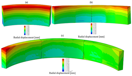
Figure 11.
The interaction between the segments when the segments are lateral: (a) first segment assembly; (b) second segment assembly; (c) third segment assembly.
Unlike the initial assembled segment at the top, when the first segment is assembled, the stress distribution at the rear of the segment is asymmetric. The stress situation in the centreline and at the front of the segment is not much different. Obviously, the stress of the segment at the rear is uneven, and stress concentration is prone to occur (Figure 9b). When the second segment is assembled, the newly assembled segment will deflect inward first, which causes the contact surface at the front of the segment to contact first. When the jack thrust is gradually applied, the contact of the segment will generate a greater squeeze. Compared with a single assembled segment, since the rotation of the segment is supported by one side segment, the distribution of the thrust of the jack in other positions of the segment is more uniform, and the stress transmission is improved. When the third segment is assembled, the stress of the final segment is closer to that at the top of the segment. The stress of the first segment will increase slightly. The main reason is that the inclination of the first segment is completely different from the inclination of the latter two segments. Therefore, the segment will show the maximum inclination, making the stress transmission mode of the first segment different.
The bending moment of the first segment at the bottom is completely opposite to that when the segment is at the top (Figure 10b). The change in the direction of gravity makes the twisted posture of the segment change to a certain extent, and the segment bends outward in the longitudinal direction. After the second segment is assembled, the extrusion of the pushed-up end causes the bending moment of the segment to increase significantly. Since the position of the newly assembled segment is different from the first segment, the bending directions of the two segments are asymmetrical. In this case, the bending moment of the first segment to the outside is much larger than that in the case where the segment is at the top. The bending moment of the third segment has been greatly improved with the further assembly of the segment. Under the clamping of the third segment, the tendency of the first segment to bend outward changes and it bends inward.
5.3. The Segment at the Bottom
When the initially assembled segment is at the bottom, compared with the first segment assembled at the top and the lateral segment, the inward deflection tendency of the front of the segment is lowest. Under the action of gravity, the segment will fall to the outside of the segment, so the displacement of the segment is relieved to a certain extent. When the second segment is assembled, the first segment is less affected by the assembly and will not undergo a large displacement change, but a certain extrusion occurs at the inner corner of the bottom of the segment (Figure 12). When the third segment is assembled, the displacement is basically small, except that the first segment and the inner corners of the segments on both sides are squeezed to a certain extent. It can be seen that under the external shape characteristics of the segment, the clamping on both sides can well maintain the stability of the segment at the bottom.
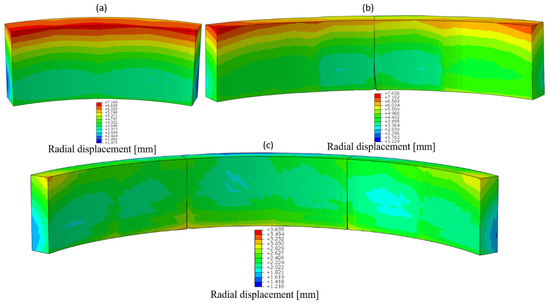
Figure 12.
The interaction between the segments when the segments at the bottom: (a) first segment assembly; (b) second segment assembly; (c) third segment assembly.
When the initial segment is assembled, although the segment is at the bottom, the segment still rotates due to excessive freedom (Figure 9c). At this time, the maximum stress of the segment is 16 N/mm2. When the second and third segments are assembled, the stress distribution of the segment is relatively uniform, and the maximum is only 0–11 N/mm2. Compared with other positions of the segment, the stress distribution of the segment is smaller. Due to the close contact between the segments, the stress transfer between the segments is relatively uniform.
At this time, the bending moment of the segment is shown in Figure 10c. Compared with assembly of the lateral segment, when the first segment is assembled, the bending moment of the segment is slightly reduced. Under the smaller deflection, the angle formed between the segments is smaller, and the segment is less biased. After the second segment is assembled, since the newly assembled segment has a higher degree of freedom, the segment will deflect to a certain extent. At this time, under the action of gravity, the segment tends to bend outward, and the bending moment is slightly increased. When the synchronous propulsion and assembly mode is applied, the final bending moments of the segments in different positions are basically the same after the three segments are assembled. During the segment assembly process, as the segment’s stability increases gradually, the influence of gravity on the segment will gradually decrease. It is necessary to focus on the possible damage to the segment when one or two segments are assembled and the segment has a large degree of freedom.
Obviously, during the construction of the synchronous propulsion and assembly mode, different positions of segments will impact the deflection of segments in the assembly process, which will have a great impact on the displacement, stress transfer, and bending of segments. When asymmetric stress acts on the segment, the assembly quality of the segment will be more compromised. It is necessary to explore possible segment damage in actual synchronous propulsion and assembly construction more finely.
6. Interactions between Segments along the Longitudinal Direction
The asymmetric stress between segments is affected by the rotation degree caused by the assembly error between segments, which can be divided into the radial rotation and lateral deflection of segments. The radial deflection of segments can be divided into radial inward deflection and radial outward deflection, which are mainly affected by the initial position of the shield machine and segments (i.e., assembly error). The tangential deflection of the segment is mainly caused by the stroke difference of the jack acting on the segment, resulting in the asymmetry of the force application device.
Different from most utilization studies, there is no contact between concrete segments in this study. This is close to the assembly of the actual project, and a certain gap will be formed between the segments due to the support of the gasket and packer.
6.1. Inward Radial Deflection Error
In the inward radial deflection model, the maximum compression damage factor of the newly assembled segment is almost linearly related to the assembly error. When the first segment is assembled, the maximum damage to the segment will be transferred from both sides of the gasket of the segment to the inner edge of the liner as the deflection angle increases. The inward radial deflection of the segment will aggravate the inward deflection during the natural assembly of the segment, which makes the segment packer more likely to generate contact stress concentration. It is also the main reason for the sudden increase in the maximum compression damage factor. This situation is gradually disintegrated due to the support on both sides during the assembly process of the segment. It can be seen from the maximum damage position of the second and third segments (Table 4) that with the assembly of the segments, the maximum damage position of the segment is transferred to the contact between the adjacent segment and the gasket place. Although there will be extrusion between the segments, the longitudinal contact quality of the segments is better than that of the rear surface, and the rotation that occurs is also smaller.
Table 4.
Damage to the segments.
In the synchronous propulsion and assembly mode, the damage possibility and severity of the segment under the inward radial deflection error are evaluated by the compression damage factor. All simulations have reached the damage limit, and the maximum compression damage factor can reach 52%, as shown in Figure 13 and Figure 14. The damage factor of 46% is marked by the dot line, so that the damage angle of the segment can be obtained intuitively. No matter where the initial segment is, the compression damage factor will form a certain mutation after a gentle rise to a certain deflection angle, which is especially obvious in the early stage of segment assembly. On the contrary, when the third segment is assembled, the compression damage factor of the segment will rise slowly and reach a certain limit. Compared with the initial position of the segment at the top and bottom, the effect of inward radial deflection on the lateral segment is smaller, and the damage growth of the segment is slower. When the segment reaches 1° deflection, the maximum damage to the segment is also smaller. The tensile damage factor of the segment undergoes little change in different positions and during the assembly process, and the peak value is 91.81%. The main tensile damage to the segment occurs at the symmetrical center of the jack, which is mainly caused by the transverse tensile stress caused by the thrust of the jack [39,40].
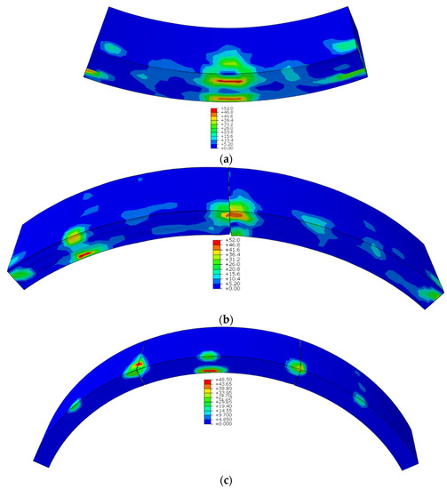
Figure 13.
Damage to a segment in the presence of inward deflection when the asymmetric error angle is 1°: (a) first segment assembly (%); (b) second segment assembly (%); (c) third segment assembly (%). (Take the segment at the top as an example.)
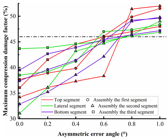
Figure 14.
Maximum compression damage factor in the presence of inward deflection.
During assembly, the outer joint width of the segment will gradually increase with the maximum inward deflection of the segment. When the initial segment is at the top, the maximum joint of the segment is 10.44 mm, as shown in Figure 15. Similar to the changing trend in the compression damage factor, when the segment damage error changes abruptly, the maximum joint width of the segment increases sharply. The increase of the joint width means that the segment has a higher possibility of damage, which can be referred to as one of the most important sources of evidence when judging the quality of segment assembly in practical engineering. At the same time, the larger joint width will reduce the sealing performance of the gasket [41,42]. While the joint width of the top segment will undergo a larger increase with greater assembly error, the segments at the other positions will gradually tend to slow down. Obviously, under the action of the larger jack, the joints of the segments will not grow all the time and will gradually stabilize when the error reaches a certain level.
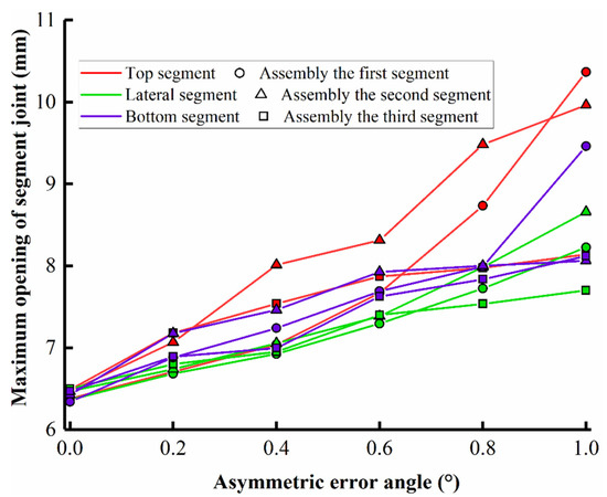
Figure 15.
Maximum opening of segment joints in the presence of inward deflection.
6.2. Outward Radial Deflection Error
In the synchronous propulsion and assembly mode, the normal assembly of the segment will cause the segment to exhibit radial deflection, and the outward radial deflection error of the segment can reduce the possibility of segment damage to a certain extent. When a segment is deflected radially outward, the stress concentration effect on the packer is reduced, so the compression damage factor of the segment will not change abruptly. With the increase of the error, the compression damage factor increases with a more moderate trend. The maximum damage to the segment is concentrated on both sides of the middle segment, mainly showing the extrusion damage of the two sides and the compression damage of the segment gasket (Figure 16 and Table 5). When the initial segment is at the bottom, the outward radial deflection has the greatest influence on the damage to the segment. When the deflection is 0.41°, the segment will be damaged, as shown in Figure 17. The main reason for this is that the newly assembled segment is more prone to outward deflection when it is at the bottom than other initial positions. There are no other supports between the segment rings to provide additional support when radially deflected outwards, so the sides of the gasket are more prone to damage. When outward deflection occurs, the maximum tensile damage factor of the segment is 92.54%. Since the thrust is unchanged, the tensile damage of the segment is not greatly affected.
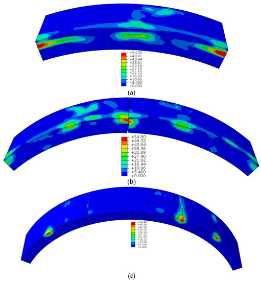
Figure 16.
Damage to segment in the presence of outward deflection when the asymmetric error angle is 1.4°: (a) first segment assembly (%); (b) second segment assembly (%); (c) third segment assembly (%). (Take the segment at the bottom as an example.)
Table 5.
Damage to the segments.
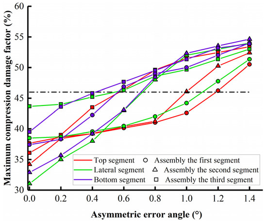
Figure 17.
Maximum compression damage factor in the presence of outward deflection.
The outer joint width of the segment gradually decreases with the increase of the outward radial assembly error, as shown in Figure 18. During the segment assembly process, the joint quality of the segment is gradually improved, which means that the assembly process reduces the deflection freedom of the segment. The action position of the jack is distributed along the center of the bearing surface, and the gasket of the segment is closer to the outer side of the segment. Although the component force caused by the outward deflection error causes the segment to deflect to the outside, the component force is too small compared to the jack thrust in the synchronous propulsion and assembly mode. Therefore, under the outward radial deflection error of the segment, the influence on the maximum joint volume of the segment is small, and the maximum reduction is only 1 mm.
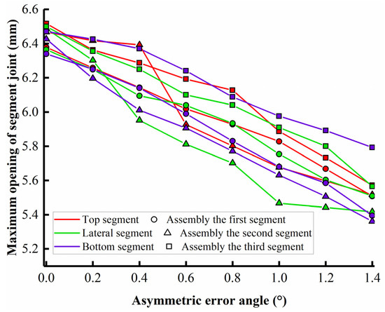
Figure 18.
Maximum opening of segment joint in the presence of outward deflection.
6.3. Lateral Deflection Error
Lateral deflection is a deflection error that often occurs in shield construction. The larger the tunnel diameter, the greater the lateral deflection range. It can be seen from Figure 19 that, compared with radial deflection, as lateral deflection error increases, the compression damage factor of the segment increases slowly. The segment can tolerate lateral deflection well. Unlike radial deflection error, when the segment is subjected to the lateral deflection error, the damage to the segment is asymmetric. The maximum possible damage position is at the bottom end of the segment’s lateral inclination (Table 6). In the process of segment assembly, the transformation of the rotation axis is an important reason for the change of the damage position. In the presence of lateral deflection error, the assembling position of the segment has little effect on the compression damage factor of the segment. When the segment is joined to the third segment, damage may occur at 1.4° (Figure 20). Although there are bolts between the segments to constrain the segment during the assembly process, the segment as a whole will show the same trend of inclination, and the extrusion effect will be superimposed. At this time, the segment will be damaged at a smaller error angle. The tensile damage factor of the segment also did not change greatly with the change of working conditions, and the peak value was 91.56%.
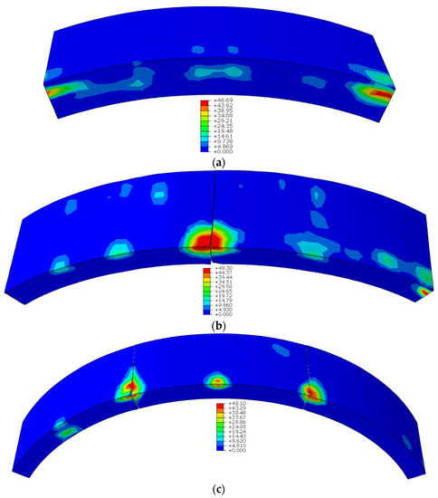
Figure 19.
Damage to segment in the presence of lateral deflection when the asymmetric error angle is 2.4°: (a) first segment assembly (%); (b) second segment assembly (%); (c) third segment assembly (%). (Take the lateral segment as an example).
Table 6.
Damage to the segments.
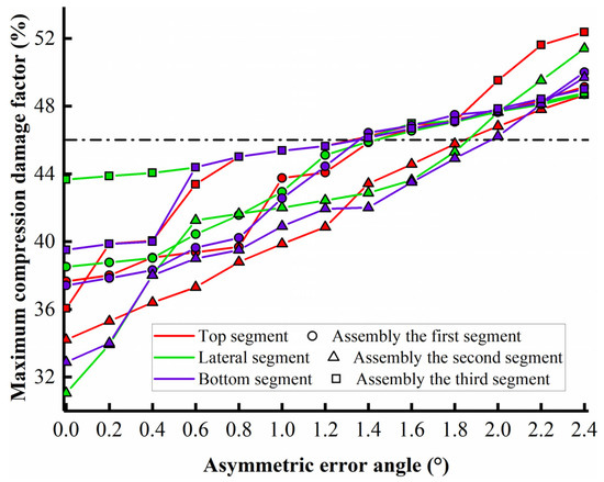
Figure 20.
Maximum compression damage factor in the presence of lateral deflection.
The maximum opening of the segment increases with the increase of the lateral deflection, as shown in Figure 21. When the segment is not assembled, the growth rate is much smaller than that of the radial deflection, and the maximum is only 9.9 mm. The joint of the segment is asymmetric, and the opening of the seam is affected by the direction of inclination. When the segment is on the side, the lateral deflection error of the segment will cause the segment to have a larger seam opening. This makes the segment more likely to be squeezed, and the larger seam quality will affect subsequent segment assembly.
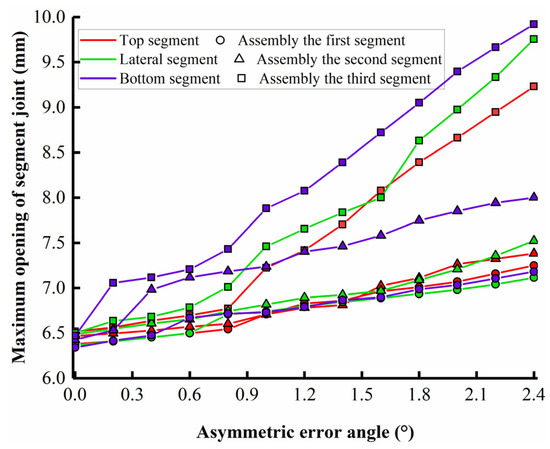
Figure 21.
Maximum opening of segment joints in the presence of lateral deflection.
Obviously, in the synchronous push-and-assemble mode, when the segment is subject to assembly error, the segment will be damaged within the maximum deflection error range. In practical engineering, it is necessary to control the assembly error of the segment within the damage angle so as to ensure the smooth development of the synchronous push-and-pull mode.
7. Conclusions
The influence of assembly error and the impact of jack thrust on the stress and structural damage of an unlooped segment is generally overlooked in the traditional shield construction process. In this paper, the interaction and damage of segments in the synchronous propulsion and assembly mode were investigated via a suite of multi-segment assembly finite element models. Through the research on the assembling position of the segment and the safety of the assembly process, the displacement, stress, and bending moment distribution of the newly assembled segment under different gravity directions were discussed. The goal of damage analysis is to explore the effects of different assembly errors, gravity directions, and the assembly process on segment damage and seam opening. The obtained results can be used to guide the smooth application of the synchronous propulsion and assembly method in practical engineering. It was found that:
- In the synchronous propulsion and assembly mode, the segment will rotate radially inward during the assembly process. Under the influence of the propulsion force, the unlooped segment will firstly be squeezed on one side and then clamped on both sides. The rotational freedom of the segment will gradually decrease.
- The direction of gravity affects the radial rotation of the segment, which in turn affects the interaction between the newly assembled segments. Inward rotation is greatest when the segment is at the top. The stress concentration of the segment will gradually decrease with the clamping effect, and the stress range is between 3.5–10.5 N/mm2.
- The bending moment of the segments that are initially assembled at different positions is different, which makes the segments present different bending conditions. With the assembly of adjacent segments, the bending of segments tends to be the same as the influence of the surrounding segments.
- In the synchronous propulsion and assembly mode of the shield, the segment may be destroyed within the assembly error range. The longitudinal thrust of the jack will be redistributed due to the posture of the segment and the interaction between the segments. The stress concentration between the contact surfaces of the segments leads to the failure of the segments. The radial deflection error is more likely to damage the segment. In actual engineering, if the assembly error reaches the segment damage angle, the operation mode of the shield needs to be adjusted.
- The maximum opening of the segment is directly related to the assembly error mode, and its peak value is strongly linearly related to the angle of the segment assembly error. Under the effect of assembly error, the maximum opening of the segment can reach 10.4 mm, which may cause the segment gasket to bear excessive pressure and reduce the waterproof performance of the segment.
Author Contributions
Conceptualization, P.L.; Data curation, J.L. and J.F.; Funding acquisition, P.L.; Investigation, X.K.; Methodology, Z.D.; Project administration, J.F.; Resources, X.K.; Visualization, J.L.; Writing—original draft, Z.D.; Writing—review & editing, P.L. and X.W. All authors have read and agreed to the published version of the manuscript.
Funding
This work was supported by the “Social Development Project of Science and Technology Commission of Shanghai Municipality (21DZ1201105)”, “The Fundamental Research Funds for the Central Universities (21D111320)”, and “Shanghai Rising-Star Program of China (18QB1403800)”.
Institutional Review Board Statement
Not applicable.
Informed Consent Statement
Not applicable.
Data Availability Statement
The data presented in this study are available on request from the corresponding author.
Acknowledgments
Thanks to research section and the members of research group for their great help in the engineering geological prospecting of the project.
Conflicts of Interest
The authors declare no conflict of interest.
References
- Liu, X.; Yang, Z.; Men, Y. Study on time-varying law of longitudinal pressure between rings of shield tunnel. J. Geotech. Eng. 2021, 43, 188–193. [Google Scholar]
- Yuan, Y.; Jiang, X.; Liu, X. Predictive maintenance of shield tunnels. Tunn. Undergr. Space Technol. 2013, 38, 69–86. [Google Scholar] [CrossRef]
- Shi, P.; Li, P. Mechanism of soft ground tunnel defect generation and functional degradation. Tunn. Undergr. Space Technol. 2015, 50, 334–344. [Google Scholar] [CrossRef] [Green Version]
- Zheng, G.; Cui, T.; Cheng, X.; Diao, Y.; Zhang, T.; Sun, J.; Ge, L. Study of the collapse mechanism of shield tunnels due to the failure of segments in sandy ground. Eng. Fail. Anal. 2017, 79, 464–490. [Google Scholar] [CrossRef]
- Fang, J.; Zhang, Z.; Zhang, J. Application of artificial freezing to recovering a collapsed tunnel in Shanghai metro No.4 line. China Civ. Eng. J. 2009, 42, 124–128. [Google Scholar]
- Jiang, X.; Zhang, X.; Wang, S.; Bai, Y.; Huang, B. Case Study of the Largest Concrete Earth Pressure Balance Pipe-Jacking Project in the World. Transp. Res. Rec. 2022, 6, 101–125. [Google Scholar] [CrossRef]
- Chen, J.; Mo, H. Numerical study on crack problems in segments of shield tunnel using finite element method. Tunn. Undergr. Space Technol. 2009, 24, 91–102. [Google Scholar] [CrossRef]
- Sugimoto, M. Causes of Shield Segment Damages During Construction. In Proceedings of the International Symposium on Underground Excavation and Tunnelling, Bangkok, Thailand, 2–4 February 2006. [Google Scholar]
- Cavalaro, S.H.P.; Blom, C.B.M.; Walraven, J.C.; Aguado, A. Structural analysis of contact deficiencies in segmented lining. Tunn. Undergr. Space Technol. 2011, 26, 734–749. [Google Scholar] [CrossRef]
- Lorenzo, S.G. In situ behaviour of an instrumented ring subjected to incipient TBM steering around a curve. Eng. Struct. 2021, 249, 113–124. [Google Scholar] [CrossRef]
- Koyama, Y. Present status and technology of shield tunnelling method in Japan. Tunn. Undergr. Space Technol. 2003, 18, 145–159. [Google Scholar] [CrossRef]
- Gemi, L.; Aksoylu, C.; Yazman. S.; Ozkilic. Y.O.; Arslan, M.H. Experimental investigation of shear capacity and damage analysis of thinned end prefabricated concrete purlins strengthened by CFRP composite. Compos. Struct. 2019, 229, 111399. [Google Scholar] [CrossRef]
- Xu, M.; Zhang, Z. Cause Analysis and Treatment of Segment Damage of Large Diameter Shield Tummel. Chin. J. Undergr. Space Eng. 2013, 9, 1705–1712. [Google Scholar]
- Krahl, P.A.; Palomo, I.I.; Almeida, S.J.C.; Henrique, S.G.; Pinto, J.N.O.; Vieira, J.L.C.M. Tolerances for TBM thrust load based on crack opening performance of fiber-reinforced precast tunnel segments. Tunn. Undergr. Space Technol. 2021, 111, 103847. [Google Scholar] [CrossRef]
- Xu, G.; He, C.; Lu, D.; Wang, S. The influence of longitudinal crack on mechanical behavior of shield tunnel lining in soft-hard composite strata. Thin-Walled Struct. 2019, 144, 106282. [Google Scholar] [CrossRef]
- Lorenzo, S.G. Structural response of concrete segmental linings in transverse interaction with the TBM. Part 2: Non-axisymmetric conditions. Tunn. Undergr. Space Technol. 2021, 116, 104024. [Google Scholar] [CrossRef]
- Lorenzo, S.G. Structural response of concrete segmental linings in transverse interaction with the TBM. Part 1: Axisymmetric conditions. Tunn. Undergr. Space Technol. 2021, 116, 104023. [Google Scholar] [CrossRef]
- Gruebl, F. Segmental rings (critical loads and damage prevention). In Proceedings of the International Symposium on Underground Excavation and Tunnelling, Bangkok, Thailand, 2–4 February 2006. [Google Scholar]
- Maidl, B.; Herrenknecht, M.; Maidl, U.; Wehrmeyer, G. Mechanised Shield Tunnelling; Ernst & Sohn: Berlin, Germany, 2012. [Google Scholar]
- Lorenzo, S.G. The role of temporary spear bolts in gasketed longitudinal joints of concrete segmental linings. Tunn. Undergr. Space Technol. 2020, 105, 103576. [Google Scholar] [CrossRef]
- Liang, X.; Guan, L.; Wen, Z.; Sun, W.; Liu, X. Experimental Study of Structural Performance of Segmental Lining of Rectangular Shield Tunnel during Construction: A Case Study of Underground Connection Gallery in Hongqiao District of Shanghai. Tunn. Constr. 2016, 36, 1456–1464. [Google Scholar]
- Wang, W.; Liu, J. Study on the influence of bolt hole assembly error on longitudinal joint misalignment. In Waterproof and Drainage Professional Committee of Tunnel and Underground Engineering Branch of China Civil Engineering Society; Shanghai Tunnel Engineering Rail Transit Design and Research Institute: Shanghai, China, 2015. [Google Scholar]
- Li, X.; Yan, Z.; Wang, Z.; Zhu, H. Experimental and analytical study on longitudinal joint opening of concrete segmental lining. Tunn. Undergr. Space Technol. 2015, 46, 52–63. [Google Scholar] [CrossRef]
- Zhu, B.; Li, X.; Fang, E.; Zhu, H. Parametric Analysis on Joint Opening Width of Concrete Segmental Lining; Geo-Shanghai: Shanghai, China, 2014. [Google Scholar]
- Zhu, H.; Huang, B.; Li, X.; Hashimoto, T. Unified model for internal force and deformation of shield segment joints and experimental analysis. Chin. J. Geotech. Eng. 2014, 36, 2153–2160. [Google Scholar]
- Li, Z.; Soga, K.; Wang, F.; Wright, P.; Tsuno, K. Behaviour of cast-iron tunnel segmental joint from the 3D FE analyses and development of a new bolt-spring model. Tunn. Undergr. Space Technol. 2014, 41, 176–192. [Google Scholar] [CrossRef]
- Zhang, X.; Zhuang, X.; Zhu, H. Study on Boundary Conditions of Three-dimensional Numerical Models for Segment Joints. Tunn. Constr. 2014, 34, 161–166. [Google Scholar]
- Gong, C.; Ding, W.; Mosalam, K.M.; Günay, S.; Soga, K. Comparison of the structural behavior of reinforced concrete and steel fiber reinforced concrete tunnel segmental joints. Tunn. Undergr. Space Technol. 2017, 68, 38–57. [Google Scholar] [CrossRef]
- Liu, M.; Liao, S.; Men, Y.; Xu, J. Analytical solutions and in-situ measurements on the internal forces of segmental lining produced in the assembling process. Transp. Geotech. 2020, 27, 100478. [Google Scholar] [CrossRef]
- Ding, W.; Gong, C.; Mosalam, K.M.; Soga, K. Development and application of the integrated sealant test apparatus for sealing gaskets in tunnel segmental joints. Tunn. Undergr. Space Technol. 2017, 63, 54–68. [Google Scholar] [CrossRef]
- Gong, C.; Ding, W.; Xie, D. Parametric investigation on the sealant behavior of tunnel segmental joints under water pressurization. Tunn. Undergr. Space Technol. 2020, 97, 103231. [Google Scholar] [CrossRef]
- Cao, W.; Shen, W. Design of Super Large and Extra Long Shield Tunnel: Case Study of Shanghai Yangtze River Crossing Tunnel; China Architecture & Building Press: Beijing, China, 2010. [Google Scholar]
- CB50010, 2010; Code for Design of Concrete Structures. China Architecture and Building Press: Beijing, China, 2010. (In Chinese)
- Weinberg, K.; Khosravani, M.R. On the tensile resistance of UHPC at impact. Eur. Phys. J. Spec. Top. 2018, 227, 167–177. [Google Scholar] [CrossRef]
- Mazars, J. Application de la Mecanique de 1’ Endommangement au au Comportement Non Lineaire et a la Rupture du Beton de Structure. Ph.D. Thesis, Université Paris VI, Paris, France, 1984. [Google Scholar]
- Lubliner, J.; Oliver, J.; Oller, S.; Onate, E. A Plastic-Damage model for concrete. Int. J. Solids Struct. 1989, 25, 299–326. [Google Scholar] [CrossRef]
- Li, M. Study on Concrete Damage. Master’s Thesis, Henan University, Henan, China, 2005. [Google Scholar]
- Li, C. Research on the Failure Behavior of Concrete Based on the Theory of Damage and Fracture. Ph.D. Thesis, Southwest Jiaotong University, Chengdu, China, 2012. [Google Scholar]
- Sundara, R.; Yogananda, C.V. A three-dimensional stress distribution problem in the anchorage zone of a post-tensioned concrete beam. Mag. Concr. Res. 1966, 18, 75–84. [Google Scholar] [CrossRef]
- Liao, L.; Albert, D.; Cavalaro, S.; Aguado, A.; Carbonari, G. Experimental and analytical study of concrete blocks subjected to concentrated loads with an application to TBM-constructed tunnels. Tunn. Undergr. Space Technol. 2015, 49, 295–306. [Google Scholar] [CrossRef] [Green Version]
- Lei, M.; Zhu, B.; Gong, C.; Ding, W.; Liu, L. Sealing performance of a precast tunnel gasketed joint under high hydrostatic pressures: Site investigation and detailed numerical modeling. Tunn. Undergr. Space Technol. 2021, 115, 104082. [Google Scholar] [CrossRef]
- Gong, C.; Ding, W.; Soga, K.; Mosalam, K.M. Failure mechanism of joint waterproofing in precast segmental tunnel linings. Tunn. Undergr. Space Technol. 2019, 84, 334–352. [Google Scholar] [CrossRef]
Publisher’s Note: MDPI stays neutral with regard to jurisdictional claims in published maps and institutional affiliations. |
© 2022 by the authors. Licensee MDPI, Basel, Switzerland. This article is an open access article distributed under the terms and conditions of the Creative Commons Attribution (CC BY) license (https://creativecommons.org/licenses/by/4.0/).