Article

Vibration and Reliability Analysis of Non-Uniform Composite Beam under Random Load

1
School of Mechanical Engineering & Automation, Northeastern University, Shenyang 110819, China
2
School of Mechanical Engineering, University of Manitoba, Winnipeg, MB R3T 2N2, Canada
3
Shenyang Institute of Automation, Chinese Academy of Sciences, Shenyang 110016, China
*
Authors to whom correspondence should be addressed.
Appl. Sci. 2022, 12(5), 2700; https://doi.org/10.3390/app12052700
Submission received: 30 January 2022 / Revised: 23 February 2022 / Accepted: 2 March 2022 / Published: 4 March 2022

Abstract

:
Non-uniform structures and composite materials have advantages in engineering applications, such as light weight design, multi-functionality, and better buckling/flutter load capacity. For composite structures under dynamic loading conditions, reliability is a key problem to be analyzed during practical operations. However, there is little research work on non-uniform composite structural reliability analysis under random load. The forced vibration response of non-uniform composite beam under random load is firstly solved by the Adomian Decomposition Method (ADM) and iterative process for reliability analysis. Different variation laws of the cross-section rigidity and mass distribution along the length of the non-uniform composite beam structures are analyzed. Various angular frequency and amplitude of random base motion acceleration following Gaussian distribution are considered. Influences of different random excitations and structural design on vibration responses and reliability are studied. The larger mean and variance of excitation frequency leads to the smaller amplitude and strain of the beam, while greater mean and variance of the base motion excitation amplitude will induce the higher maximum amplitude and strain values and lower reliability. The influences of structural design on reliability are studied. The reliability increases with the increment of taper ratios of the host beam and composite layer. The iteration mathematical model and numerical solutions proposed in this paper can be used to solve and analyze vibration responses and reliability of general non-uniform composite beam structures under arbitrary excitation during a certain period of time.

1. Introduction

Non-uniform composite beams, including functionally graded materials (FGM) beams, have important applications in engineering because they can change geometric and material properties, while most of the excitations applied on mechanical structures in nature and engineering practice are random forces. In recent years, the problems of mechanical structure damage caused by vibration have achieved more and more attention, which make the vibration reliability analysis of non-uniform composite beam structures under random load of great significance.
Before the study of non-uniform composite beams, researchers have done a lot of work on uniform composite beams dynamics. In references [1,2,3,4,5,6,7,8,9], the free vibration of a composite beam structure is solved by the finite element method. In addition to the finite element method, there are some other methods to solve the free vibration responses of composite beams. By using a global higher order beam theory, Matsunaga analyzed natural frequencies and buckling stresses of simply supported multilayered composite beams through the method of power series expansion of displacement components [10]. Atlihan et al. used differential quadrature method (DQM) to analyze the free vibration of laminated composite beams [11]. The natural frequencies of longitudinal and transverse vibration modes have been obtained by using the method of power series [12]. Except for the free vibration analysis, Raja, Prathap and Sinha developed a control scheme based on the linear quadratic regulator/independent modal space control (LQR/IMSC) method and used this to do the active vibration control of composite sandwich beams [13]. Ramanamurthy, Chandrasekaran and Nishant used finite element method for damage detection [14]. Xu et al. proved the feasibility of the ultrasonic non-destructive testing with the combination of a strain measurement for fatigue crack details detection of headed shear studs in composite beams [15]. Tao et al. obtained the fitting formula for calculating the equivalent flexural stiffness of composite beams through extensive parameter analysis, and they studied and analyzed the equivalent flexural stiffness of composite frame beams to evaluate their vertical deflection [16]. Kim et al. studied the free and forced vibration of cracked laminated composite beam through the Jacobi–Ritz method and the first-order shear deformation theory (FSDT) [17,18].
In addition to research and understanding of the uniform composite beam, some researchers have also used various methods to solve and analyze vibration responses of the non-uniform beams. For the geometrically non-uniform beams, the vibration responses of non-uniform beams were solved and analyzed by the amatrix transfer method in [19,20,21,22]. In addition, Wu investigated the free vibration characteristics of a non-uniform cantilever beam carrying multiple two degree-of-freedom spring–damper–mass systems by means of two finite element methods, FEM1 and FEM2 [23]. Ho and Chen used Timoshenko beam theory, Hamilton principle and differential transformation method (DTM) to study the vibration of axially loaded non-uniform spinning twisted Timoshenko beam [24]. Martinez Castro et al. gave the semi-analytic solution of moving load problem, which is used to analyze the stress of multi-span uniform beam and non-uniform beam under a moving load [25]. Mazanoglu and Sabuncu studied the bending vibration of non-uniform Rayleigh beams with single-edge and double-edge cracks [26]. Chen et al. presented the design, test and analysis of a non-uniform thickness piezoelectric beam for impact vibration energy harvesting. [27]. Clementi et al. determined the frequency response curve of a non-uniform beam under nonlinear vibration by the multiple time scale method analytically [28]. Based on the nonlocal elastic theory, Chakraverty and Behera studied the free vibration of non-uniform Euler–Bernoulli nanobeams by using the Rayleigh–Ritz method [29]. Celik studied the free vibration of non-uniform Euler–Bernoulli beams under different support conditions through the Chebyshev wavelet collocation method [30]. For beam structures with anisotropic material properties (FGM), the finite element method was used to solve and analysis the free vibration of FGM beam in references [31,32,33]. Differential transformation method and transfer matrix method (TMM) were also used to study the free vibration of an FGM beam in references [34,35]. Abdelrahman et al. developed an analytical solution method using Navier’s procedure to study the dynamic behavior of carbon nanotube reinforced functional gradient (FG) beams on two parameter elastic foundation under a moving load [36]. Esen et al. studied and analyzed the free vibration and dynamic response of an S-shaped FG Timoshenko beam model under a moving load based on Navier’s method [37]. There is also some research work on the non-uniform FGM beam. Rajasekaran used the differential transformation (DT) based dynamic stiffness approach to study the free vibration of axially functionally graded non-uniform beams under different boundary conditions [38]. Heshmati and Daneshmand described the effect of different profile variations on vibrational properties of non-uniform beams made of graded porous materials [39]. Under the framework of nonlocal strain gradient theory, Rajasekaran and Khaniki used the Lagrange interpolation method, Gaussian quadrature method and Wilson multiplier method to study the bending, buckling and vibration behavior of depth functionally graded in depth direction non-uniform nanobeams [40]. Adomian Decomposition Method (ADM) has been used to analyze the free and forced vibration of general non-uniform cone beams with axial functionally graded material by Keshmiri et al. [41,42,43].
Based on dynamic modeling and analysis of different structures, their reliability analysis under random load excitation can be conducted. Siddiqui and Ahmad carried out nonlinear dynamic analysis of the platform for response calculation. The response history obtained has been used for the fatigue reliability analysis of Tension leg platform (TLP) tethers under long crested random sea and associated wind [44]. Jensen et al. used a standard gradient-based algorithm with a line search to solve the reliability optimization problem of a structural system under random load [45]. Liu and Zhang deduced the calculation expression of the mean value of structural dynamic reliability under stationary random excitation, and conveniently obtained the dynamic reliability analysis results of random structures under random excitation [46]. Singh et al. determined the fatigue reliability of an automotive crankshaft by stochastically inducing random loads [47]. In summary, there have been many studies on the dynamic analysis of composite structures and non-uniform beams, and the vibration and reliability analysis of uniform structures and mechanical parts with certain design under random loads is also a common and well-studied problem in engineering. However, to the best of the authors’ knowledge, there is no research on the vibration reliability analysis of a non-uniform composite beam under a random load. Considering the various mechanical properties as well as unknown response and strain/stress distribution of the non-uniform structures made from multiple composite layers, the reliability of such structures can be different from traditional uniform structures as novel research [48,49], especially under different random dynamic loads. There is no explicit expression for the random load whose excitation frequency and amplitude are changing, so the analytical solution of forced vibration at each time point needs to be solved by iterative method. To deal with this challenge, a model combining ADM and iteration numerical process is proposed to solve the vibration response and dynamic stress-distribution of the non-uniform composite beams for reliability analysis in this research.
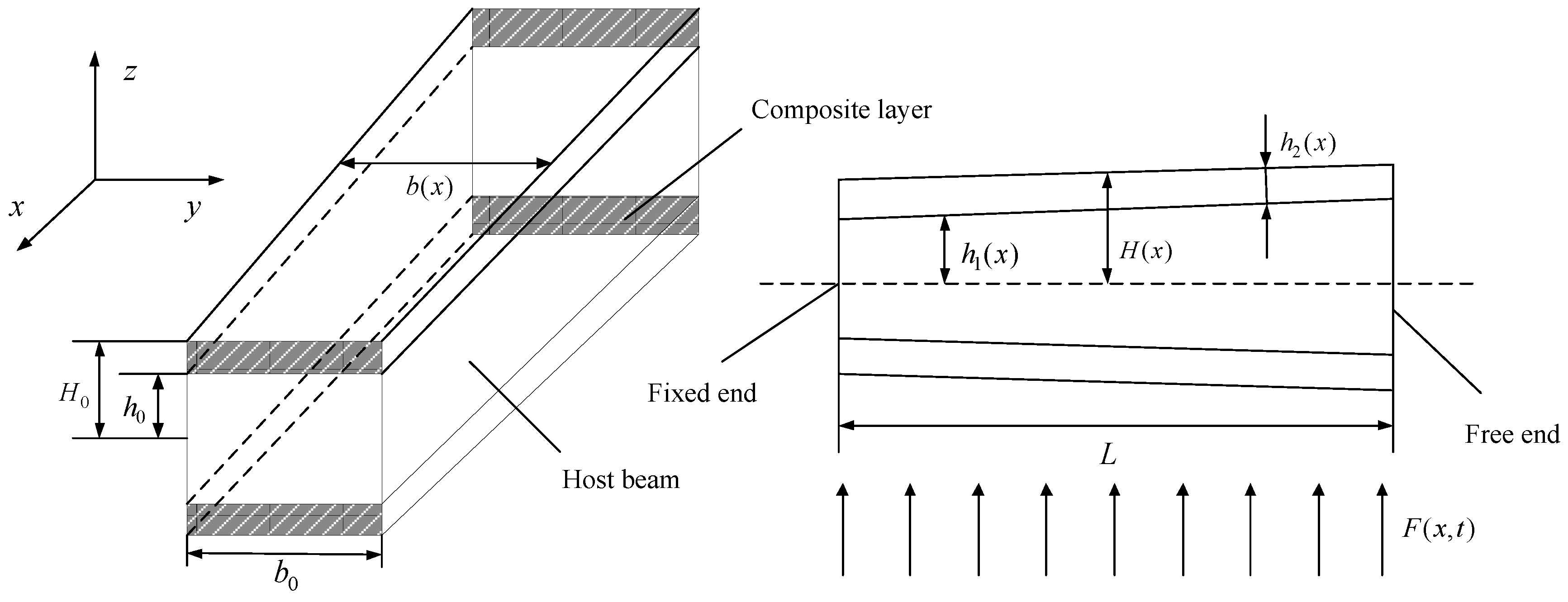
In this paper, the vibration responses and reliability of a general non-uniform beam with tapered composite layers and host beam under random load are calculated and analyzed. The cross-section rigidity and mass distribution can be adjusted by changing the volume proportion of different materials of the non-uniform laminated composite beam. The angular frequency and amplitude of random base motion acceleration accord with Gaussian distribution. The vibration mode shapes and nature frequencies are calculated, and the vibration solution under random base motion excitation is solved by the iteration numerical method. In the parameter studies, the influences of the base motion excitation frequencies variation on amplitude and strain of beam are studied. Then, the effects of base motion excitation amplitudes on vibration responses and reliability are analyzed. In addition, the vibration responses and reliability in different periods of time are calculated. Finally, the reliability of non-uniform beams with different taper ratios of composite layers and host beam is solved and analyzed.

2. Theoretical Model

In this section, ADM is used to solve the natures (nature frequencies and mode shapes) of the non-uniform composite beam. Then, an iterative model is used to describe and solve the vibration response and reliability of the non-uniform composite beam under random load. This random excitation is caused by base motion, and its angular frequency and amplitude of acceleration conform to Gaussian distribution with specified mean and variance. Finally, the definition and calculation method of vibration reliability are given.

2.1. Natures (Nature Frequencies and Mode Shapes) of Non-Uniform Composite Beam

In this study, a sample non-uniform rectangular composite cantilever beam structure with varied cross section is analyzed and shown in Figure 1. In the middle of the composite beam is a host beam made of aluminum, and composite layers of piezoelectric ceramic material are pasted above and below the host beam. At the left fixed end, the length, width and thickness of the composite beam and the thickness of the host beam are L , b 0 , 2 H 0 , and 2 h 0 , respectively. The thicknesses of the host beam and composite layer at x position are 2 h 1 ( x ) and 2 h 2 ( x ) . x is the position variable along the beam length. The width and thickness of the composite beam at x position are b ( x ) and 2 H ( x ) = 2 h 1 ( x ) + 2 h 2 ( x ) . F ( x , t ) is the random excitation.
The mass distribution and cross-section rigidity at x position of the composite beam are
ρ ( x ) A ( x ) = ρ 1 A 1 ( x ) + ρ 2 A 2 ( x ) ,
E ( x ) I ( x ) = ( 2 / 3 ) b ( x ) h 1 3 ( x ) ( E 1 E 2 ) + ( 2 / 3 ) E 2 b ( x ) H 3 ( x ) ,
where A ( x ) = 2 H ( x ) b ( x ) ,   ρ 1 , A 1 ( x ) , E 1 , ρ 2 , A 2 ( x ) and E 2 are mass density, cross-sectional area and modulus of elasticity of host beam and composite layer.
The equation of free vibration of a non-uniform composite beam without considering damping is given below,
ρ ( x ) A ( x ) 2 w ( x , t ) t 2 + 2 x 2 [ E ( x ) I ( x ) 2 w ( x , t ) x 2 ] = 0 ,
where w ( x , t ) is the deflection function and t is the time.
The boundary conditions are defined as:
{ w ( x , t ) | x = 0 = 0 w ( x , t ) x | x = 0 = 0 ,
{ E ( x ) I ( x ) 2 w ( x , t ) x 2 | x = L = 0 x [ E ( x ) I ( x ) 2 w ( x , t ) x 2 ] | x = L = 0 = 0 .
By using the mode superposition method, w ( x , t ) in Equation (2) can be decomposed into two parts,
w ( x , t ) = i = 1 W i ( x ) q i ( t ) ,
where W i ( x ) is the i -th mode shape and q i ( t ) is the i -th corresponding generalized coordinate of the free vibration response or external force. For free vibration analysis solving the natural frequencies and mode shape functions, considering the orthogonality of a linear vibration problem, substituting Equation (6) into Equation (3), one ordinary differential equation corresponding to the i -th mode is obtained as,
E ( x ) I ( x ) d 4 W i ( x ) d x 4 + 2 d d x [ E ( x ) I ( x ) ] d 3 W i ( x ) d x 3 + d 2 d x 2 [ E ( x ) I ( x ) ] d 2 W i ( x ) d x 2 ω i 2 ρ ( x ) A ( x ) W i ( x ) = 0 ,
where ω i is the i -th natural frequency. In order to solve the above equation, ADM is applied. The operator form of the Equation (7) is rewritten as,
L x [ W i ( x ) ] = 2 d d x [ E ( x ) I ( x ) ] W i ( x ) E ( x ) I ( x ) d 2 d x 2 [ E ( x ) I ( x ) ] W i ( x ) E ( x ) I ( x ) + ω i 2 ρ ( x ) A ( x ) W i ( x ) E ( x ) I ( x ) ,
where L x is the fourth order differential operator.
L x 1 is applied on the both sides of Equation (8) at the same time, where L x 1 is the fourth-order integral operator.
W i ( x ) = C 1 + C 2 x + C 3 x 2 2 ! + C 4 x 3 3 ! L x 1 [ 2 d d x [ E ( x ) I ( x ) ] W i ( x ) E ( x ) I ( x ) + d 2 d x 2 [ E ( x ) I ( x ) ] W i ( x ) E ( x ) I ( x ) ω i 2 ρ ( x ) A ( x ) W i ( x ) E ( x ) I ( x ) ] ,
where C 1 to C 4 are constants that can be determined by boundary conditions, the detailed progress defining C 1 C 4 can be found in [36,37,38].
W i ( x ) is written in series form,
W i ( x ) = k = 0 W k i ( x ) ,
where k is the number of terms in series form. The larger the value of k , the more accurate the solution. A precise solution is often obtained with very small values of k [50].
Substituting Equation (10) into Equation (9), we have,
k = 0 W k i ( x ) = C 1 + C 2 x + C 3 x 2 2 ! + C 4 x 3 3 ! L x 1 [ 2 d d x [ E ( x ) I ( x ) ] E ( x ) I ( x ) k = 0 W k i ( x ) + d 2 d x 2 [ E ( x ) I ( x ) ] E ( x ) I ( x ) k = 0 W k i ( x ) ω i 2 ρ ( x ) A ( x ) k = 0 W k i ( x ) E ( x ) I ( x ) ] .
For each term in the series, we can have,
W 0 i ( x ) = C 1 + C 2 x + C 3 x 2 2 ! + C 4 x 3 3 ! ,
W k + 1 i ( x ) = L x 1 [ 2 d d x [ E ( x ) I ( x ) ] E ( x ) I ( x ) W k i ( x ) + d 2 d x 2 [ E ( x ) I ( x ) ] E ( x ) I ( x ) W k i ( x ) ω i 2 ρ ( x ) A ( x ) W k i ( x ) E ( x ) I ( x ) ] k 0 .
The natural frequencies can be obtained by introducing the mode functions into the boundary conditions and solving the eigenvalue problem. The detailed solving process of the mode shape functions and nature frequencies of the non-uniform composite beam can be found in references [41,42,43] and is hence not provided here.

2.2. Vibration Model of Non-Uniform Composite Beam under Random Load

After the natures of the beam structure are solved by free vibration analysis and ADM, the forced vibration response can be solved using the modal analysis and Duhamel integral. The forced vibration governing equation of non-uniform composite beam considering damping under action of random load F ( x , t ) is given below,
ρ ( x ) A ( x ) 2 w ( x , t ) t 2 + 2 x 2 [ E ( x ) I ( x ) 2 w ( x , t ) x 2 + C ( x ) I ( x ) 3 w ( x , t ) x 2 t ] = F ( x , t ) = ρ ( x ) A ( x ) φ 2 Y sin ( φ t ) ,
where C ( x ) is the strain rate damping coefficient. ρ ( x ) A ( x ) φ 2 Y sin ( φ t ) is the distribution force generated by base motion. The displacement and acceleration of base motion are y = Y sin ( φ t ) and a = φ 2 Y sin ( φ t ) , and A a = φ 2 Y is the amplitude of acceleration.   Y and φ are amplitude and angular frequency of base motion.
Substituting Equation (6) into Equation (14), the following equation can be obtained,
ρ ( x ) A ( x ) i = 1 W i ( x ) d 2 q i ( t ) d t 2 + d 2 d x 2 [ E ( x ) I ( x ) i = 1 q i ( t ) d 2 W i ( x ) d x 2 + C ( x ) I ( x ) i = 1 d q i ( t ) d t d 2 W i ( x ) d x 2 ] = ρ ( x ) A ( x ) φ 2 Y sin ( φ t ) .
Based on the understanding from the free vibration governing equation, for the i -th mode of free vibration, we have,
d 2 d x 2 [ E ( x ) I ( x ) d 2 W i ( x ) d x 2 ] = ρ ( x ) A ( x ) ω i 2 W i ( x ) .  
With the understanding from the relationship given in the above equation, both sides of Equation (15) multiplied by W j ( x ) and integrated from 0 to L in space domain leads to,
0 L ρ ( x ) A ( x ) i = 1 W i ( x ) d 2 q i ( t ) d t 2 W j ( x ) d x + 0 L d 2 d x 2 [ E ( x ) I ( x ) i = 1 q i ( t ) d 2 W i ( x ) d x 2 + C ( x ) I ( x ) i = 1 d q i ( t ) d t d 2 W i ( x ) d x 2 ] W j ( x ) d x = Y sin ( φ t ) 0 L ρ ( x ) φ 2 A ( x ) W j ( x ) d x .
Since in general, the damping function does not possess the orthogonality property, it is assumed that the structural damping is in the form of C ( x ) = α E ( x ) where α is a constant. According to the orthogonality of normal vibration modes, Equation (18) for the i -th mode can be obtained, while α ω i 2 = 2 ξ i ω i is defined,
d 2 q i ( t ) d t 2 + 2 ξ i ω i d q i ( t ) d t + ω i 2 q i ( t ) = F i ( t ) = φ 2 Y sin ( φ t ) 0 L ρ ( x ) A ( x ) W i ( x ) d x 0 L ρ ( x ) A ( x ) W i 2 ( x ) d x ,
where ξ i is the modal damping ratio of the corresponding i -th order natural mode.
Equation (18) can be solved by the Duhamel integral, and the final time domain solution for i -th mode is,
q i t = 1 ω d i 0 t F i τ · e ξ i ω i t τ · sin ω d i t τ d τ = 0 L ρ x A x W i x d x 2 ω d i ξ i ω i cos ω d i t + sin ω d i t ξ i 2 ω i 2 φ 2 + ω d i 2 φ e ξ i ω i t + ( ξ i 2 ω i 2 φ 2 + ω d i 2 ) sin φ t 2 ξ i φ ω i cos φ t ω d i φ 2 Y / ( ( ω d i 5 + ( 2 ξ i 2 ω i 2 2 φ 2 ) ω d i 3 + ( ξ i 2 ω i 2 + φ 2 ) 2 ( ξ i 2 ω i 2 + φ 2 ) 2 ω d i ) ( 0 L ρ ( x ) A ( x ) W i 2 ( x ) d x ) ) ,
where ω d i is the damped frequency corresponding to the i-th vibration mode, ω d i = 1 ξ i 2 ω i , F i ( t ) is the force coefficient corresponding to the i-th vibration mode.
According to Equations (12), (14) and (19), the response of the non-uniform composite beam structure is,
w f o r c e ( x , t ) = i = 1 W i ( x ) q i ( t ) = i = 1 W i ( x ) ω d i 0 t F i ( t ) · e ξ i ω i ( t τ ) sin ( ω d i ( t τ ) ) d τ .

2.3. Iteration Process Considering Random Load

The premise of the iterative method is that at t = 0 s, the initial condition of vibration is known, and there is no force applied to the beam. At this time, the beam is considered to be at rest, and the deflection and velocity at any position of the beam are,
{ w ( x , t ) = 0 d w ( x , t ) d t = 0 .
Because some variables, like deflection, corresponding generalized coordinate, excitation, in each iteration step are different in the process of iteration of the system, they are defined by iteration step subscripts. The subscript 1 represents these variables in the first time period/iteration step in period t 1 t 2 . The subscript 2 represents these variables in the second time period/iteration step in period t 2 t 3 and so on. The subscript n represents these variables in the n -th time period/iteration step in period t n t n + 1 .
According to the engineering experience, the step length of each iteration is determined by base motion excitation frequency, Δ t = t n + 1 t n = 1 10 × f ( n ) , 1 n , and n is the number of iteration steps, f ( n ) is the base motion excitation frequency during time period t n t n + 1 .
The initial condition for time t 1 ( t 1 = 0 s) is,
{ w ( x , t 1 ) = 0 d w ( x , t ) d t | t = t 1 = 0 .
When the time is in t 1 t 2 , there is no free vibration and the response of the forced vibration is,
w 1 ( x , t ) = i = 1 W i ( x ) q 1 i ( t ) = i = 1 W i ( x ) 1 ω d i 0 t t 1 F 1 i ( τ + t 1 ) e ξ i ω i ( t t 1 τ ) sin ( ω d i ( t t 1 τ ) ) d τ   ( t 1 t t 2 ) .
To clarify the iteration progress, we start the derivation from the second time step, t 2 t 3 , while the first step vibration solutions is only from the Duhamel integral assuming the structure is at rest before excitation as described in Equation (23). The free vibration response from the initial condition at t 2 is,
w f r e e 2 ( x , t ) = i = 1 W i ( x ) q f r e e 2 i ( t ) = i = 1 W i ( x ) e ξ i ω i t ( A 2 i cos ω d i t + B 2 i sin ω d i t )   ( t 2 t t 3 ) ,  
A 2 i and B 2 i are determined by q 1 i ( t 2 ) and d q 1 i ( t ) d t at t = t 2 .
e ξ i ω i t 2 ( A 2 i cos ω d i t 2 + B 2 i sin ω d i t 2 ) = q 1 i ( t 2 ) ,  
( ω d i cos ω d i t 2 ξ i ω i sin ω d i t 2 ) e ξ i ω i t 2 B 2 i ( ω d i sin ω d i t 2 + ξ i ω i cos ω d i t 2 ) e ξ i ω i t 2 A 2 i = d q 1 i ( t ) d t | t = t 2 .
A 2 i and B 2 i can be obtained by the above formula,
B 2 i = e ξ i ω d i t 2 ( ( ξ i ω i q 1 i ( t 2 ) + d q 1 i ( t ) d t | t = t 2 ) cos ( ω d i t 2 ) + ω d i q 1 i ( t 2 ) sin ( ω d i t 2 ) ) ω d i ,
A 2 i = q 1 i ( t 2 ) e ξ i ω i t 2 B 2 i sin ( ω d i t 2 ) cos ( ω d i t 2 ) .
During the period, t 2 t 3 , the total vibration response is,
w 2 ( x , t ) = i = 1 W i ( x ) q 2 i ( t ) = i = 1 W i ( x ) ( q f r e e 2 i ( t ) + q f o r c e 2 i ( t ) ) = i = 1 W i ( x ) · e ξ i ω i t A 2 i cos ω d i t + B 2 i sin ω d i t + 1 ω d i 0 t t 2 F 2 i τ + t 2 e ξ i ω i t t 2 τ sin ω d i t t 2 τ d τ t 2 t t 3 ,
where q f r e e 2 i ( t ) is i -th corresponding generalized coordinate of free vibration during t 2 t 3 , q f o r c e 2 i ( t ) is i -th corresponding generalized coordinate of the external force induced vibration during t 2 t 3 .
For general vibration solution during the iteration, when the time is t n t n + 1 , the total vibration response is, hence,
w n ( x , t ) = i = 1 W i ( x ) q n i ( t ) = i = 1 W i ( x ) ( q f r e e n i ( t ) + q f o r c e n i ( t ) ) = i = 1 W i ( x ) · e ξ i ω i t A n i cos ω d i t + B n i sin ω d i t + 1 ω d i 0 t t n F n i τ + t n e ξ i ω i t t n τ sin ω d i t t n τ d τ t n t t n + 1 ,
where q f r e e n i ( t ) is i -th corresponding generalized coordinate of free vibration during t n t n + 1 , q f o r c e n i ( t ) is i -th corresponding generalized coordinate of the external force during t n t n + 1 .
A n i and B n i are given as follows with known q n 1 i ( t n ) from the previous iteration step,
B n i = e ξ i ω d i t n ( ( ξ i ω i q n 1 i ( t n ) + d q n 1 i ( t ) d t | t = t n ) cos ( ω d i t n ) + ω d i q n 1 i ( t n ) sin ( ω d i t n ) ) ω d i ,
A n i = q n 1 i ( t n ) e ξ i ω i t n B n i sin ( ω d i t n ) cos ( ω d i t n ) .

2.4. Vibration Reliability Analysis

In the process of vibration, the excessive vibration response (stress or amplitude) of the structure will lead to the damage and failure of the structure or system. According to the reliability theory, the state function of general system with vibration is defined as,
{ G i j ( ε j , ε i ) = ε j ε i γ 0             s e c u r i t y G i j ( ε j , ε i ) = ε j ε i γ > 0             i n v a l i d ,
where ε j is the deflection of non-uniform composite beam under a random load at a certain time point, ε i is the reference safety value of the strain of the Bernoulli–Euler beam with the parameters researched in this work, γ is a specific value and is generally 10% times of ε i .
The vibration reliability of the non-uniform composite beam under a random load during a period of time is,
R = P ( G i j ( ε j , ε i ) 0 ) = N G i j ( ε j , ε i ) 0 N t o t a l ,
where N G i j ( ε j , ε i ) 0 is the number of iteration points satisfying the state function greater than 0, and N t o t a l is the total number of iteration points in the iterative calculation results within a period of time.

3. Numerical Studies, Results and Discussion

A non-uniform rectangular cantilever composite beam with positive exponential cross-section variation function is chosen for numerical case studies. The length of the beam is fixed as L = 0.2 m and the thickness of the left end of the non-uniform composite beam is H 0 = 0.003 m. The dimensions at x position along the length of the beam are b ( x ) = b 0 e h x , h 1 ( x ) = h 0 e n x and h 2 ( x ) = ( H 0 h 0 ) e m x . h is the taper ratio of the width variation of the composite beam. n and m are taper ratios for the variations of thickness of the host beam and the composite layers, respectively. The material properties of the composite beam are ρ 1 = 2.7 × 10³ kg/m3, ρ 2 = 7.8 × 10³ kg/m3, E 1 = 7 × 10¹⁰ Pa, E 2 = 68.9 × 10⁹ Pa, for the host beam and composite layers, respectively. The reference value of maximum strain is ε i = 0.0035.

3.1. Model Validation

In order to prove the correctness of the mathematical model proposed in this paper, the first two order dimensionless natural frequencies of the non-uniform composite beam structure shown in Figure 1 and the non-uniform beam structure in reference [43] are calculated and compared. The thickness of the composite layer in the current model is set to be a very small value of 0.00001 m to match the structure studied in reference [43]. The parameters are shown in Table 1. The calculation results are shown in Table 2.
It can be seen from Table 2 that when the thickness of the composite layer is very small, the first two natural frequencies of the two beam structures are very close, which proves the correctness of the mathematical model in this paper.

3.2. Influences of Different Design Parameters on Natural Frequencies

For composite structures, different design parameters will change the inherent properties of the structure. By adjusting the structural design parameters, the damage caused by excessive structural amplitude (resonance) can be effectively avoided. The influences of different design parameters on the natural frequencies (first three orders, unit rad/s) of non-uniform composite beam are shown in Table 3, Table 4, Table 5, Table 6 and Table 7. Constant parameters for each study are shown in the table captions. The variation ranges of m and n are to study the influence trend of different parameters taper ratios of different composite layers and host beam on the natural frequency of non-uniform composite non-uniform beam structure. As for the core material in the composite beam in our paper with relatively less effect on stiffness, the variation of the host beam taper ratio, n , is set in a relatively larger range to see its effect on natural frequency variation more obviously.
It can be seen from the results in Table 3, Table 4, Table 5, Table 6 and Table 7 that within the range of parameters studied, for the three layered non-uniform composite beam with parameter variation ranges in this paper, the nature frequencies increase with the increment of h 0 , n , m and decrease a bit with the increment of h . b 0 has little effect on nature frequencies. First, for the change of h and b 0 (change of width), both stiffness and mass at certain cross section of the beam changes linearly with the beam width variation leading to less effect on natural frequency variation. However, for the ranges studied of h 0 , n and m , their increment will increase the thickness and stiffness of the beam structure in cubic function but the mass linearly. Therefore, within a certain change range, the more significant increment of stiffness compared with the mass change will lead to the increase of natural frequency. On the other hand, for the first vibration mode as an example, if n and m are further increased, the mass can be more concentrated at the beam free end, where the large beam thickness will not affect the whole modal stiffness significantly, so the natural frequency can decrease. In summary, for different non-uniform composite beams, natural frequencies variations for different modes depend on the stiffness and mass distribution following different shapes of the cross-section variation along the beam length. It is almost impossible to show all natural frequency variations of different non-uniform composite beam. The studied parameter ranges were just chosen to show a clear natural frequency variation trend.

3.3. Vibration Responses under Random Base Motion Excitation

In order to study the influences of the random base motion excitation on the vibration characteristics of non-uniform composite beam, the vibration responses of non-uniform composite beam with b 0 = 0.005 m, h 0 = 0.001 m, n = 2, m = 2.5 and h = 1.5 under base motion with random frequency and amplitude of acceleration and harmonic base motion were simulated and compared based on the proposed iterative method. The frequency and amplitude of acceleration of random load accord with φ ~ N ( 200 , ( 200 / 15 ) 2 ) rad/s and A a ~ N ( 50 , 10 2 ) m/s2, respectively, while the constant frequency and amplitude of acceleration of the base motion are 200 rad/s and 50 m/s2, which are the mid-values of the random base motion excitation case. The vibration responses in time domain at the free end of the non-uniform composite beam are shown in Figure 2a,b. The power spectral density (PSD) plots of the time domain signal are shown in Figure 2c,d. The PSD function of MATLAB software is used to convert the time-domain vibration response into power/frequency (dB/Hz) with decibel notation definition of the corresponding power concept, which makes the PSD analysis results easier to read.
From Figure 2a,b, while the frequency and amplitude of acceleration of random base motion excitation change with Gaussian distribution, with the increment of time, the deflection at the free end of the non-uniform composite beam will not approach a steady state with variable amplitude. This fully shows the randomness characteristics of the random load. However, for a non-uniform composite beam excited by base motion with constant frequency and amplitude of acceleration which are the average of the ones of the random load, the vibration responses (deflection) at the free end experience a process from transient to steady state with the time increment. The amplitude at the free end of beam under a random load is larger than the one under base motion with constant frequency and amplitude of acceleration, and the variation trend of deflection is unpredictable. From Figure 2c,d, PSD of time domain signal under random frequency and amplitude has obvious ‘volatility’. This kind of uncontrollability explains the significance of studying the vibration reliability under a random load.

3.4. Influences of Different Ranges of Base Motion Excitation Angular Frequency on Vibration Responses

During the vibration process under random base motion excitation, the influences of exaction amplitude and frequency with different means and variances on vibration characteristics are different. Firstly, the influences of base motion excitation frequency on vibration responses were studied. The amplitude of acceleration of base motion accord with Gaussian distribution with A a ~ N ( 50 , 10 2 ) . The amplitude of base motion is Y = A a φ 2 . Four groups of base motion excitation angular frequencies with Gaussian distribution and standard deviation of 1/15 of the average value were selected for analysis. The specific base motion excitation frequency variation ranges are φ 1 ~ N ( 200 , ( 200 / 15 ) 2 ) rad/s, φ 2 ~ N ( 440 , ( 440 / 15 ) 2 ) rad/s, φ 3 ~ N ( 3600 , ( 3600 / 15 ) 2 ) rad/s, and φ 4 ~ N ( 11000 , ( 11000 / 15 ) 2 ) rad/s. The first three natural frequencies of non-uniform composite beam with b 0 = 0.005 m, h 0 = 0.001 m, n = 2, m = 2.5 and h = 1.5 are 439.2 rad/s, 3555.4 rad/s and 10832.3 rad/s. The frequency ranges of φ 2 , φ 3 and φ 4 can cover the first, second and third beam natural frequency, respectively. In addition, another four groups of base motion excitation angular frequencies with Gaussian distribution and different means and variances were selected. The specific value ranges are φ 5 ~ N ( 200 , 20 2 ) rad/s, φ 6 ~ N ( 440 , 44 2 ) rad/s, φ 7 ~ N ( 2810 , 518 2 ) rad/s and φ 8 ~ N ( 8360 , 1628 2 ) rad/s. The values of φ 6 , φ 7 and φ 8 can ensure the following relationships 1 / 2 ω 1 φ 6 3 / 2 ω 1 , 1 / 2 ω 1 φ 7 3 / 2 ω 2 , 1 / 2 ω 1 φ 8 3 / 2 ω 3 and cover the first one, two and three beam natural frequencies, respectively. The maximum vibration amplitude and strain at all locations along the length of the beam with different variation ranges of base motion excitation frequency are shown in Figure 3.
As can be seen from Figure 3, when the angular frequencies of several groups of random loads cover the first, second and third and the first one, two and three order natural frequencies, the larger the mean and variance of base motion excitation frequency, the smaller the maximum amplitude and strain of beam in the same period of time can be excited. In engineering practice, the vibration amplitude of the structure can be controlled by changing the base motion excitation frequency. From the iteration numbers with different excitation frequency, we can know that when the base motion excitation frequency only covers the third order natural frequency, the high-frequency component accounts for the largest proportion in base motion excitation frequency within the same period of time.

3.5. Influences of Mean and Variance of Base Motion Excitation Amplitude on Vibration Responses and Reliability

The same as base motion excitation frequency, the influences of different base motion excitation amplitudes on vibration responses and reliability were studied in this section. The value ranges of frequency and amplitude of acceleration of base motion are φ ~ N ( 200 , ( 200 / 15 ) 2 ) rad/s and 0 A a 100 m/s2. The amplitude of base motion is Y = A a φ 2 . The value range of base motion excitation amplitude is determined by the range of excitation frequency and amplitude of acceleration, which is 0   Y 5.625 × 10 3 m. The parameters of beam are b 0 = 0.005 m, h 0 = 0.001 m, n = 2, m = 2.5 and h = 1.5. Firstly, the influences of different mean values of base motion excitation amplitude on vibration responses and reliability under the same variance were studied. The ranges of four groups of base motion excitation amplitudes are Y 1 ~ N ( 2 × 10 3 , ( 0.125 × 10 3 ) 2 ) m, Y 2 ~ N ( 3 × 10 3 , ( 0.125 × 10 3 ) 2 ) m, Y 3 ~ N ( 4 × 10 3 , ( 0.125 × 10 3 ) 2 ) m and Y 4 ~ N ( 5 × 10 3 , ( 0.125 × 10 3 ) 2 ) m. In addition, the influences of base motion excitation amplitudes with different variances on vibration responses and reliability were studied. The values ranges of base motion excitation amplitude are Y 5 ~ N ( 3 × 10 3 , ( 0.005 × 10 3 ) 2 ) m, Y 6 ~ N ( 3 × 10 3 , ( 0.18 × 10 3 ) 2 ) m, Y 7 ~ N ( 3 × 10 3 , ( 0.355 × 10 3 ) 2 ) m and Y 8 ~ N ( 3 × 10 3 , ( 0.525 × 10 3 ) 2 ) m. The influences of different means and variances of base motion excitation amplitude on vibration responses and reliability of the beam are shown in Figure 4.
As can be seen from Figure 4, when the frequency and amplitude of acceleration of base motion accord with Gaussian distribution, the greater the mean and variance of the base motion excitation amplitude, the greater the value of the maximum amplitude and strain and lower reliability of beam are induced. With a larger mean value of the excitation amplitude, the upper and lower limits of the interval become larger and the reliability hence becomes smaller. The excitation with larger variance but the same mean value leads to a higher possibility of large strain happening on the tested structure. When the safe and failure data points appear in the same number, the failure probability will hence increase, and the reliability will decrease. The range and magnitude of vibration response of non-uniform composite beam structure can be controlled and adjusted by changing the mean and variance of excitation amplitude of the random load.

3.6. Vibration Responses and Reliability Analysis in Different Periods of Time

The uncertainty of frequency and amplitude of random base motion excitation leads to different vibration responses and reliability results within different time periods. The maximum amplitude and strain of beam with b 0 = 0.005 m, h 0 = 0.001 m, n = 2, m = 2.5 and h = 1.5 in the time periods of 0–20 s, 20–40 s, 40–60 s, 60–80 s, 80–100 s, 100–120 s, 120–140 s, 140–160 s and 160–180 s are calculated, and vibration reliability in the time points of 20 s, 40 s, 60 s, 80 s, 100 s, 120 s, 140 s, 160 s and 180 s under the same random load with ( A a ~ N ( 50 , 10 2 ) m/s2 and φ ~ N ( 200 , ( 200 / 15 ) 2 ) rad/s) were analyzed, respectively. The calculation results are shown in Figure 5.
As can be seen from Figure 5, the maximum amplitude and strain of beam in different periods of time is different; because the reliability is not only related to the maximum strain in this time period but also to the number of loading cycles. The result shows that in the relatively short period of time (<120 s), the reliability may increase or decrease with the increment of the time period. However, when the period of time of analysis increases above a certain value (>120 s), the reliability shows a downward trend reaching to a converged value as a whole. The results of reliability under different time lengths are different, and the calculation time duration for reliability analysis should be according to the actual operation and measurement conditions.

3.7. Reliability Analysis of Non-Uniform Composite Beam with Different Design Parameters

In order to study the influences of different design parameters on the vibration reliability, the reliability of non-uniform beam with different taper ratios, n and m , were calculated under the same random load with ( A a ~ N ( 50 , 10 2 ) m/s2 and φ ~ N ( 200 , ( 200 / 15 ) 2 ) rad/s). Other constant parameters are b 0 = 0.005 m, h 0 = 0.001 m and h = 1.5. When studying the influence of the change of m on vibration reliability, n is a constant of 2. Similarly, when n changes, the value of m is a constant of 2.5. The results are shown in Figure 6.
It can be seen from Figure 6 that within the range of parameters studied, the reliability of the non-uniform composite beam increases with the increment of n and decreases with the increment of m . It can be concluded that the taper design itself of the non-uniform composite beam will affect the structural reliability. It should be noted that the exact structural reliability variation trend will also depend on the excitation. The iteration mathematic model proposed in this paper can be used to solve and analyze the vibration responses and reliability of non-uniform composite beam with different design parameters. For the multiple layered composite beam, different design parameters lead to different reliability results. Reasonable design under random loading condition with certain variation range of its frequency and amplitude can enhance structural reliability.

4. Conclusions

In this paper, an iterative method is proposed to solve the forced vibration responses and reliability of non-uniform composite beam under random load. Considering the change of frequency and acceleration amplitude of base motion excitation in the iteration process, the vibration response of beam in each short time period/iteration step is calculated by ADM and Duhamel integral considering both the transient and steady response. Through numerical studies, the results reveal the following conclusions:
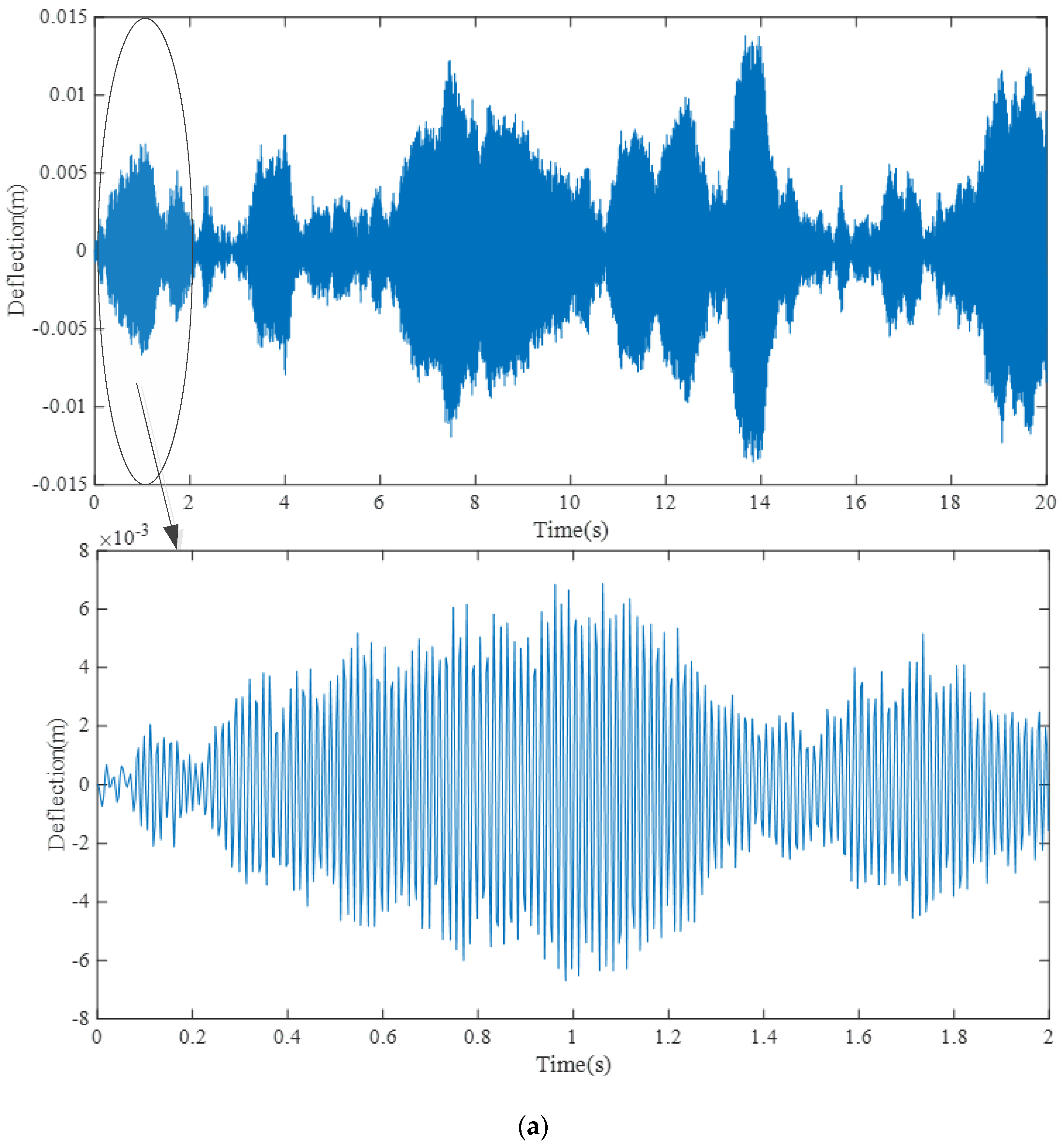
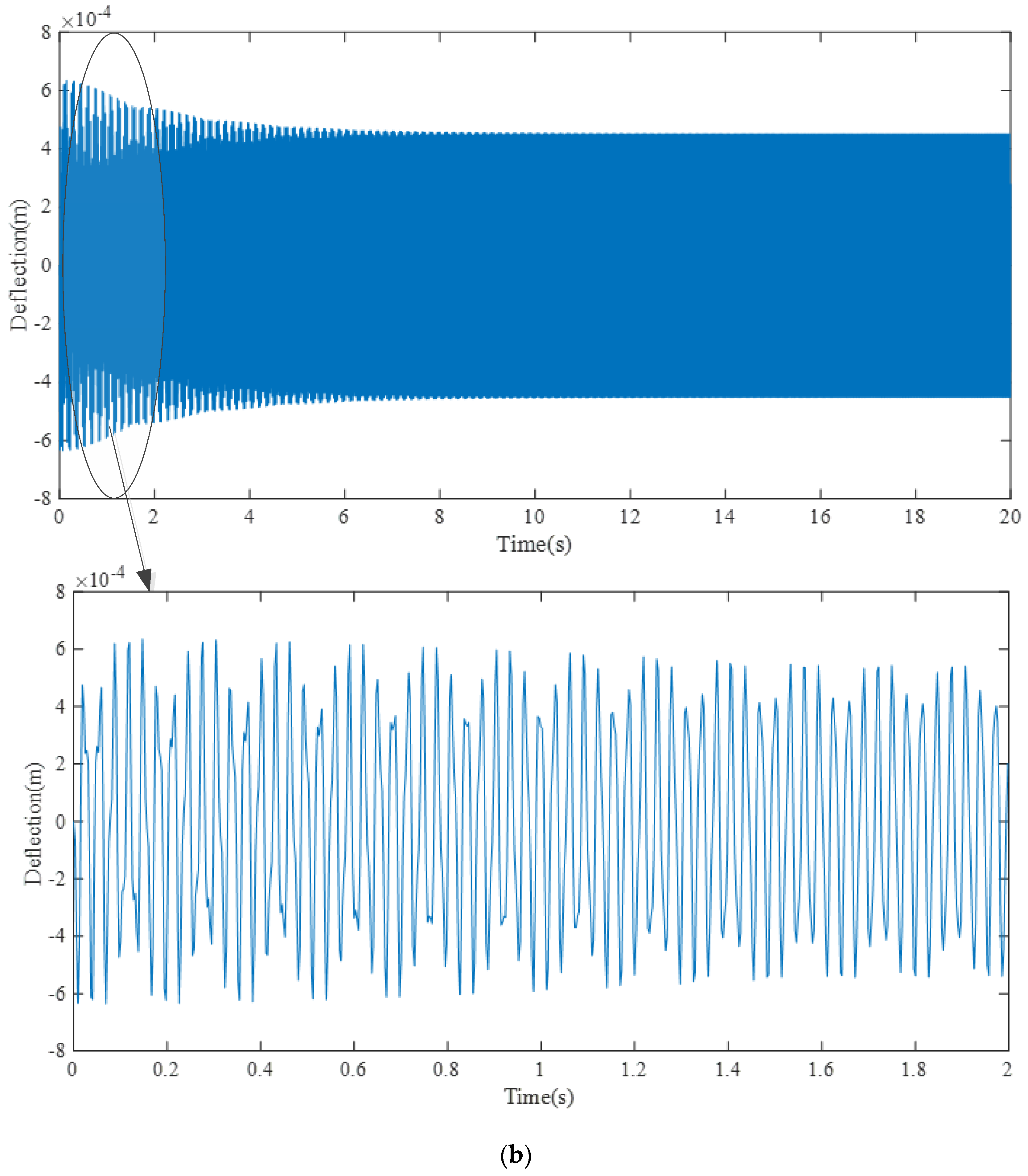
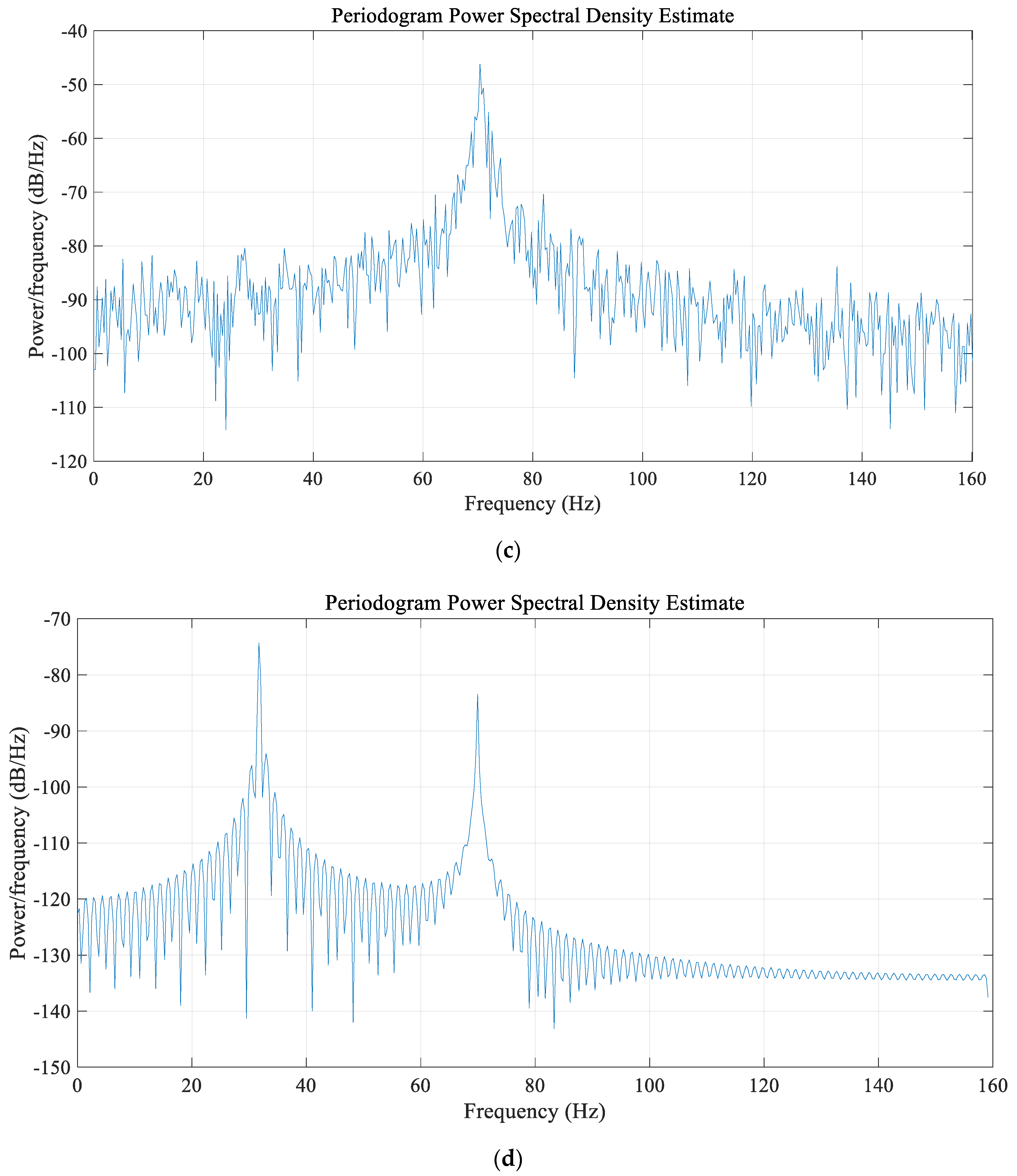
(1) ADM is used to be combined with iteration progress solving non-uniform composite beam structural vibration under random load. The correctness of the mathematical model is proved. Comparing solutions under random and harmonic base motion, the vibration response under random load shows the randomness and non-frequency characteristics, and its vibration amplitude is larger than the one under the same level harmonic excitation.
(2) Within the ranges of studied design parameters, the composite beam nature frequencies increase with the increment of h 0 , n , m and decrease with the increment of h . b 0 has little effect on nature frequencies.
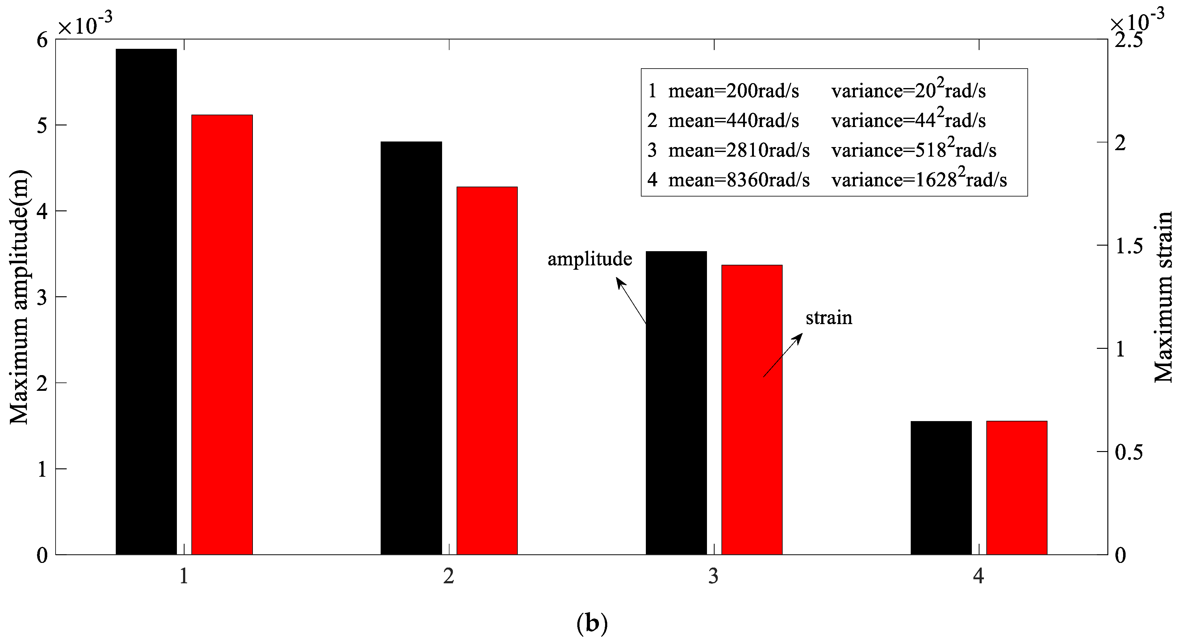
(3) The higher mean value and variance of base motion excitation frequency, the smaller amplitude and maximum strain of the non-uniform composite beam can be excited.
(4) The greater mean and variance of the base motion excitation amplitude, the greater vibration amplitude and strain of the non-uniform composite beam, and the lower the vibration reliability in the same time period.
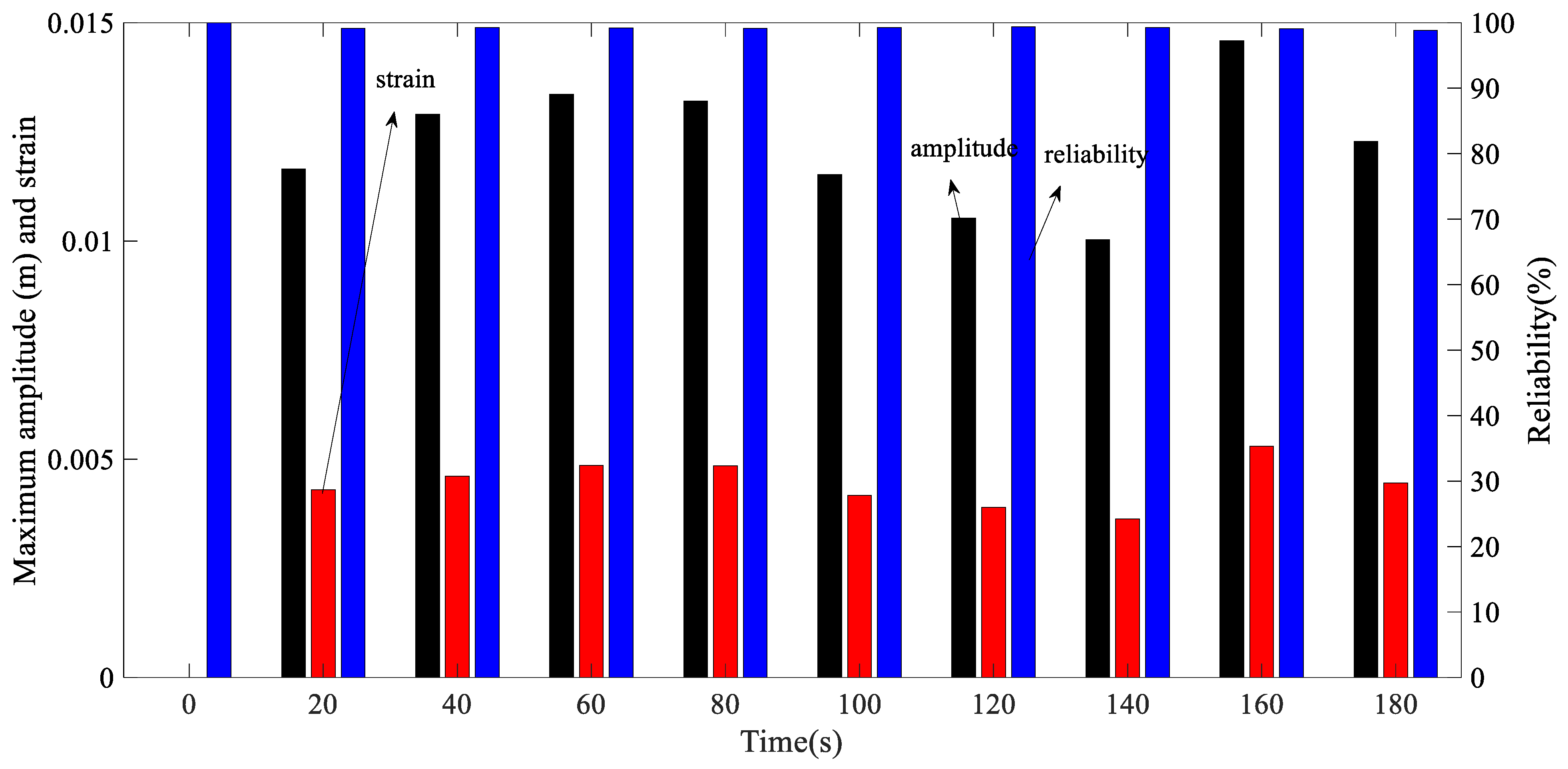
(5) The vibration reliability will increase or decrease with the increment of operation time considered, but the overall trend is downward if the operation time of the system is long enough.
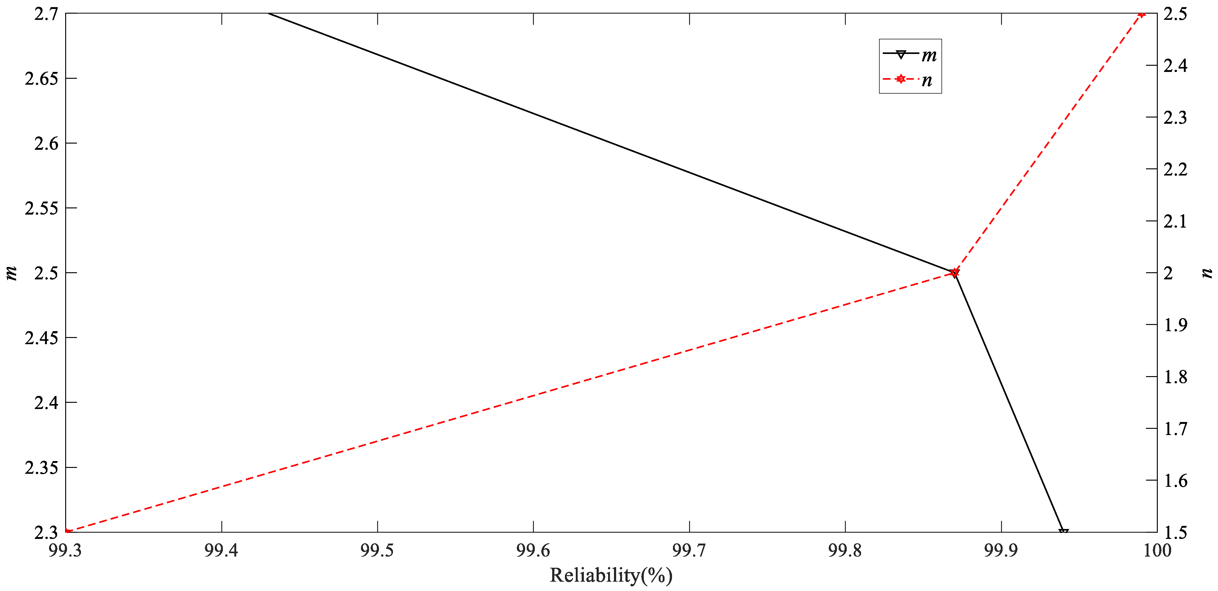
(6) The reliability of the non-uniform composite beam increases with the increment of n and decreases with the increment of m . For the multiple layered composite beam, different design parameters lead to different reliability results. Reasonable design can enhance structural reliability.
(7) However, the research results obtained within the range of parameters studied occur when the operation time is long enough. When the calculation/analysis time duration is very short, the results may change. The statement that the operation time is long enough means that the analyzed period should be enough to ensure that the excitation amplitude and frequency distribution law can be illustrated and judged from the data points of the random loads in the calculation process.

Author Contributions

Conceptualization, P.W. and N.W.; methodology, P.W.; software, P.W.; validation, P.W., H.L. and Z.S.; formal analysis, P.W.; investigation, P.W.; data curation, P.W.; writing—original draft preparation, P.W.; writing—review and editing, N.W.; supervision, N.W.; project administration, N.W. and Z.S.; funding acquisition, N.W. and Z.S. All authors have read and agreed to the published version of the manuscript.

Funding

This research was funded by National Natural Science Foundation of China (No. 51775097) and the University of Manitoba, and the Natural Sciences and Engineering Research Council of Canada (NSERC). This research was also funded by the China Scholarship Council (File No. 202106080045).

Institutional Review Board Statement

Not applicable.

Informed Consent Statement

Not applicable.

Data Availability Statement

Not applicable.

Conflicts of Interest

The authors declare that they have no conflict of interest.

References

  1. Kisa, M. Free vibration analysis of a cantilever composite beam with multiple cracks. Compos. Sci. Technol. 2004, 64, 1391–1402. [Google Scholar] [CrossRef]
  2. Perel, V.Y. Finite element analysis of vibration of delaminated composite beam with an account of contact of the delamination crack faces, based on the first-order shear deformation theory. J. Compos. Mater. 2005, 39, 1843–1876. [Google Scholar] [CrossRef]
  3. Jun, L.; Hongxing, H.; Rongying, S. Dynamic finite element method for generally laminated composite beams. Int. J. Mech. Sci. 2008, 50, 466–480. [Google Scholar] [CrossRef]
  4. Allahverdizadeh, A.; Mahjoob, M.J.; Eshraghi, I.; Asgharifard-S, P. Effects of electrorheological fluid core and functionally graded layers on the vibration behavior of a rotating composite beam. Meccanica 2012, 47, 1945–1960. [Google Scholar] [CrossRef]
  5. Cünedioğlu, Y.; Beylergil, B. Free vibration analysis of laminated composite beam under room and high temperatures. Struct. Eng. Mech. 2014, 51, 111–130. [Google Scholar] [CrossRef] [Green Version]
  6. Monti, A.; El Mahi, A.; Jendli, Z.; Guillaumat, L. Experimental and finite elements analysis of the vibration behaviour of a bio-based composite sandwich beam. Compos. B Eng. 2017, 110, 466–475. [Google Scholar] [CrossRef] [Green Version]
  7. Osman, M.Y.; Suleiman, O.M.E. Free vibration analysis of laminated composite beams using finite element method. Int. J. Eng. Res. Adv. Technol. 2017, 3, 5–22. [Google Scholar]
  8. Lee, J. Free vibration analysis of delaminated composite beams. Comput. Struct. 2000, 74, 121–129. [Google Scholar] [CrossRef]
  9. Carrera, E.; Demirbas, M.D.; Augello, R. Evaluation of Stress Distribution of Isotropic, Composite, and FG Beams with Different Geometries in Nonlinear Regime via Carrera-Unified Formulation and Lagrange Polynomial Expansions. Appl. Sci. 2021, 11, 10627. [Google Scholar] [CrossRef]
  10. Matsunaga, H. Vibration and buckling of multilayered composite beams according to higher order deformation theories. J. Sound Vib. 2001, 246, 47–62. [Google Scholar] [CrossRef]
  11. Atlihan, G.; Çallioğlu, H.; Şahin Çonkur, E.; Topcu, M.; Yücel, U. Free vibration analysis of the laminated composite beams by using DQM. J. Reinf. Plast. Compos. 2009, 28, 881–892. [Google Scholar] [CrossRef]
  12. Li, B.; Dong, L.; Zhu, L.; Chen, X. On the natural frequency and vibration mode of composite beam with non-uniform cross-section. J. Vibroeng. 2015, 17, 2491–2502. [Google Scholar]
  13. Raja, S.; Prathap, G.; Sinha, P.K. Active vibration control of composite sandwich beams with piezoelectric extension-bending and shear actuators. Smart Mater. Struct. 2002, 11, 63. [Google Scholar] [CrossRef]
  14. Ramanamurthy, E.V.V.; Chandrasekaran, K.; Nishant, G. Vibration analysis on a composite beam to identify damage and damage severity using finite element method. Int. J. Eng. Sci. Technol. 2011, 3, 5865–5888. [Google Scholar]
  15. Xu, J.; Sun, H.; Chen, W.; Guo, X. Experiment-Based Fatigue Behaviors and Damage Detection Study of Headed Shear Studs in Steel–Concrete Composite Beams. Appl. Sci. 2021, 11, 8297. [Google Scholar] [CrossRef]
  16. Tao, M.X.; Li, Z.A.; Zhou, Q.L.; Xu, L.Y. Analysis of Equivalent Flexural Stiffness of Steel–Concrete Composite Beams in Frame Structures. Appl. Sci. 2021, 11, 10305. [Google Scholar] [CrossRef]
  17. Kim, S.; Kim, K.; Ri, M.; Paek, Y.; Kim, C. A semi-analytical method for forced vibration analysis of cracked laminated composite beam with general boundary condition. J. Ocean Eng. Mar. Energy 2021, 6, 40–53. [Google Scholar] [CrossRef]
  18. Kim, K.; Choe, K.; Kim, S.; Wang, Q. A modeling method for vibration analysis of cracked laminated composite beam of uniform rectangular cross-section with arbitrary boundary condition. Compos. Struct. 2019, 208, 127–140. [Google Scholar] [CrossRef]
  19. Wu, J.S.; Chen, C.T. A continuous-mass TMM for free vibration analysis of a non-uniform beam with various boundary conditions and carrying multiple concentrated elements. J. Sound Vib. 2008, 311, 1420–1430. [Google Scholar] [CrossRef]
  20. Zhang, Z.; Chen, F.; Zhang, Z.; Hua, H. Vibration analysis of non-uniform Timoshenko beams coupled with flexible attachments and multiple discontinuities. Int. J. Mech. Sci. 2014, 80, 131–143. [Google Scholar] [CrossRef]
  21. Tan, G.; Liu, Y.; Gong, Y.; Shen, Y.; Liu, Z. Free vibration of the cracked non-uniform beam with cross section varying as polynomial functions. KSCE J. Civ. Eng. 2018, 22, 4530–4546. [Google Scholar] [CrossRef]
  22. Liu, H.; Wei, Z.; Tan, G.; Han, Y.; Liu, Z. Vibratory characteristics of cracked non-uniform beams with different boundary conditions. J. Mech. Sci. Technol. 2019, 33, 377–392. [Google Scholar] [CrossRef]
  23. Wu, J.J. Use of effective stiffness matrix for the free vibration analyses of a non-uniform cantilever beam carrying multiple two degree-of-freedom spring–damper–mass systems. Comput. Struct. 2003, 81, 2319–2330. [Google Scholar] [CrossRef]
  24. Ho, S.H.; Chen, C.K. Free transverse vibration of an axially loaded non-uniform spinning twisted Timoshenko beam using differential transform. Int. J. Mech. Sci. 2006, 48, 1323–1331. [Google Scholar] [CrossRef]
  25. Martinez-Castro, A.E.; Museros, P.; Castillo-Linares, A. Semi-analytic solution in the time domain for non-uniform multi-span Bernoulli–Euler beams traversed by moving loads. J. Sound Vib. 2006, 294, 278–297. [Google Scholar] [CrossRef]
  26. Mazanoglu, K.; Sabuncu, M. Flexural vibration of non-uniform beams having double-edge breathing cracks. J. Sound Vib. 2010, 329, 4181–4191. [Google Scholar] [CrossRef]
  27. Chen, S.; Zhou, J.; Sun, J.; Hu, J.H. Piezoelectric beam with non-uniform thickness for vibration energy harvesting. In Proceedings of the Symposium on Piezoelectricity, Acoustic Waves, and Device Applications (SPAWDA), Shanghai, China, 23–25 November 2012; pp. 61–64. [Google Scholar]
  28. Clementi, F.; Demeio, L.; Mazzilli, C.E.N.; Lenci, S. Nonlinear vibrations of non-uniform beams by the MTS asymptotic expansion method. Contin. Mech. Thermodyn. 2015, 27, 703–717.22. [Google Scholar] [CrossRef]
  29. Chakraverty, S.; Behera, L. Free vibration of non-uniform nanobeams using Rayleigh–Ritz method. Phys. E 2015, 67, 38–46. [Google Scholar] [CrossRef]
  30. Celik, I. Free vibration of non-uniform Euler–Bernoulli beam under various supporting conditions using Chebyshev wavelet collocation method. Appl. Math. Model. 2018, 54, 268–280. [Google Scholar] [CrossRef]
  31. Alshorbagy, A.E.; Eltaher, M.A.; Mahmoud, F.F. Free vibration characteristics of a functionally graded beam by finite element method. Appl. Math. Model. 2011, 35, 412–425. [Google Scholar] [CrossRef]
  32. Mashat, D.S.; Carrera, E.; Zenkour, A.M.; Al Khateeb, S.A.; Filippi, M. Free vibration of FGM layered beams by various theories and finite elements. Compos. B Eng. 2014, 59, 269–278. [Google Scholar] [CrossRef]
  33. Xu, Y.; Qian, Y.; Song, G. Stochastic finite element method for free vibration characteristics of random FGM beams. Appl. Math. Model. 2016, 40, 10238–10253. [Google Scholar] [CrossRef] [Green Version]
  34. Suddoung, K.; Charoensuk, J.; Wattanasakulpong, N. Vibration response of stepped FGM beams with elastically end constraints using differential transformation method. Appl. Acoust. 2014, 77, 20–28. [Google Scholar] [CrossRef]
  35. Yang, E.C.; Zhao, X.; Li, Y.H. Free vibration analysis for cracked FGM beams by means of a continuous beam model. Shock. Vib. 2015, 2015, 197049. [Google Scholar] [CrossRef]
  36. Abdelrahman, A.A.; Esen, I.; Daikh, A.A.; Eltaher, M.A. Dynamic analysis of FG nanobeam reinforced by carbon nanotubes and resting on elastic foundation under moving load. Mech. Based Des. Struct. Mach. 2021, 3, 1–24. [Google Scholar] [CrossRef]
  37. Esen, I.; Abdelrahman, A.A.; Eltaher, M.A. On vibration of sigmoid/symmetric functionally graded nonlocal strain gradient nanobeams under moving load. Int. J. Mech. Mater. Des. 2021, 17, 721–742. [Google Scholar] [CrossRef]
  38. Rajasekaran, S. Buckling and vibration of axially functionally graded nonuniform beams using differential transformation based dynamic stiffness approach. Meccanica 2013, 48, 1053–1070. [Google Scholar] [CrossRef]
  39. Heshmati, M.; Daneshmand, F. Vibration analysis of non-uniform porous beams with functionally graded porosity distribution. Proc. Inst. Mech. Eng. L 2019, 233, 1678–1697.25. [Google Scholar] [CrossRef]
  40. Rajasekaran, S.; Khaniki, H.B. Bending, buckling and vibration analysis of functionally graded non-uniform nanobeams via finite element method. J. Braz. Soc. Mech. Sci. 2018, 40, 1–35. [Google Scholar] [CrossRef]
  41. Keshmiri, A.; Wu, N.; Wang, Q. Free vibration analysis of a nonlinearly tapered cone beam by Adomian decomposition method. Int. J. Struct. Stab. Dyn. 2018, 18, 1850101. [Google Scholar] [CrossRef]
  42. Keshmiri, A.; Wu, N.; Wang, Q. Vibration analysis of non-uniform tapered beams with nonlinear FGM properties. J. Mech. Sci. Technol 2018, 32, 5325–5337. [Google Scholar] [CrossRef]
  43. Keshmiri, A.; Wu, N.; Wang, Q. A new nonlinearly tapered FGM piezoelectric energy harvester. Eng. Struct. 2018, 173, 52–60. [Google Scholar] [CrossRef]
  44. Siddiqui, N.A.; Ahmad, S. Fatigue and fracture reliability of TLP tethers under random loading. Mar. Struct. 2001, 14, 331–352. [Google Scholar] [CrossRef]
  45. Jensen, H.A.; Valdebenito, M.A.; Schuëller, G.I.; Kusanovic, D.S. Reliability-based optimization of stochastic systems using line search. Comput. Methods Appl. Mech. Eng. 2009, 198, 3915–3924. [Google Scholar] [CrossRef]
  46. Liu, M.; Zhang, H.M. Dynamic Reliability of Stochastic Truss Structures under Random Load. Appl. Mech. Mater. 2014, 525, 218–221. [Google Scholar] [CrossRef]
  47. Singh, S.S.K.; Abdullah, S.; Ariffin, A.K. Fatigue reliability assessment in time domain using stochastic-induced random stress loads due to limited experimental data. Eng. Fail. Anal. 2020, 117, 104794. [Google Scholar] [CrossRef]
  48. Qin, Z.; Pang, X.; Safaei, B.; Chu, F. Free vibration analysis of rotating functionally graded CNT reinforced composite cylindrical shells with arbitrary boundary conditions. Compos. Struct. 2019, 220, 847–860. [Google Scholar] [CrossRef]
  49. Safaei, B. The effect of embedding a porous core on the free vibration behavior of laminated composite plates. Steel Compos. Struct. 2020, 35, 659–670. [Google Scholar]
  50. Adomian, G. A review of the decomposition method in applied mathematics. J. Math. Anal. Appl. 1988, 135, 501–544. [Google Scholar] [CrossRef] [Green Version]
Figure 1. Main and right views of a non-uniform composite beam.
Applsci 12 02700 g001
Figure 2. Vibration responses of non-uniform composite beam at free end under base motion with random frequency and amplitude of acceleration and harmonic base motion: (a) vibration responses under random frequency and amplitude of base motion acceleration; (b) vibration responses under constant frequency and amplitude of base motion acceleration; (c) PSD of time domain signal under random frequency and amplitude of base motion acceleration; (d) PSD of time domain signal under constant frequency and amplitude of base motion acceleration.
Applsci 12 02700 g002aApplsci 12 02700 g002bApplsci 12 02700 g002c
Figure 3. Maximum vibration amplitude and strain with different ranges of frequency: (a) covering the first, second and third natural frequencies; (b) covering the first one, two and three natural frequencies.
Applsci 12 02700 g003aApplsci 12 02700 g003b
Figure 4. Influences of mean and variance of base motion excitation amplitude on vibration responses (maximum amplitude and strain) and reliability: (a) Influences of mean of base motion excitation amplitude on vibration responses and reliability; (b) Influences of variance of base motion excitation amplitude on vibration responses and reliability.
Applsci 12 02700 g004
Figure 5. Vibration responses (maximum amplitude and strain) and reliability of beam in different periods of time.
Applsci 12 02700 g005
Figure 6. Vibration reliability of non-uniform composite beam with different m and n .
Applsci 12 02700 g006
Table 1. Parameters in model validation.
ParametersMethod in Reference [43]Present Method
b 0 (m)0.10.1
h 0 (m)0.00499-
H 0 (m)0.0050.005
h 0-
n 0.10.1
m 0-
ρ 1 (kg/m3)7.8 × 1037.8 × 103
ρ 2   (kg/m3)7.8 × 103-
E 1 (Pa)2.1 × 10112.1 × 1011
E 2 (Pa)68.9 × 10⁹-
L (m)0.30.3
Table 2. Comparison of the first two natural frequencies.
First OrderSecond Order
Method in reference [43]2.60594766319.41237317
Present method2.60595744019.41239643
Table 3. Influences of b0 on natural frequencies with m = 2.5, n = 2, h = 1.5, h0 = 0.001 m.
b0 (m)First Order (rad/s)Second Order (rad/s)Third Order (rad/s)
0.006439.20051973555.38318710,832.33073
0.005439.20054403555.38347310,832.32140
0.004439.20051143555.38365310,832.34972
Table 4. Influences of h0 on natural frequencies with m = 2.5, n = 2, h = 1.5, b0 = 0.005 m.
h0 (m)First Order (rad/s)Second Order (rad/s)Third Order (rad/s)
0.0015471.20570803814.39686311,586.11082
0.001439.20054403555.38347310,832.32140
0.0005415.19471953348.45293910,236.74275
Table 5. Influences of n on natural frequencies with m = 2.5, h0 = 0.001 m, h = 1.5, b0 = 0.005 m.
nFirst Order (rad/s)Second Order (rad/s)Third Order (rad/s)
2.5449.51611973593.46377311,030.09338
2439.20054403555.38347310,832.32140
1.5434.26147303510.59143010,642.28582
Table 6. Influences of m on natural frequencies with n = 2, h0 = 0.001 m, h = 1.5, b0 = 0.005 m.
mFirst Order (rad/s)Second Order (rad/s)Third Order (rad/s)
2.7443.32224333564.15477410,935.10283
2.5439.20054403555.38347310,832.32140
2.3438.86760193540.85225210,729.68121
Table 7. Influences of h on natural frequencies with n = 2, m = 2.5, h0 = 0.001 m, b0 = 0.005 m.
hFirst Order (rad/s)Second Order (rad/s)Third Order (rad/s)
2434.46237663506.96637210,798.87618
1.5439.20054403555.38347310,832.32140
1449.52615853596.04700710,863.78753
Publisher’s Note: MDPI stays neutral with regard to jurisdictional claims in published maps and institutional affiliations.

