Abstract
Ambient light is an energy-harvesting source that can recharge a battery with less human interaction and can be used to prolong the operational time of the Internet of Things, e.g., mobile phones and wearable devices. Available light energy is insufficient for directly charging mobile phones and wearable devices, but it can supplement batteries to power some low-energy-consuming critical functions of the wearable device, especially in low-power consumption wearables. However, in an emergency scenario when the battery’s operational time is not sufficient or a battery charging source is unavailable, a solution is required to extend the limited battery span for mobile and wearable devices. This work presents the bottlenecks and new advancements in the commercialization of photovoltaics for smartphones and wearable technologies based on ambient light energy harvesting. A new technique, in which a smartphone cover is used as a solar concentrator to enhance light energy harvesting associated with algorithms, is experimentally demonstrated. Our research outcomes show that solar concentrators can improve light intensity by approximately 1.85 and 1.43 times at 90° and 71° angles, respectively, thus harvesting more ambient light energy at 2500 lx light intensity in a typical office environment. Type-1 PV and Type-2 PV cells were able to charge the additional battery in 8 h under 2500 lx lighting intensity in an indoor office environment. A system and logic algorithm technique is presented to efficiently transfer harvested light energy to perform low-energy consumption operations in a device, in order to improve the operational time of the device’s battery.
1. Introduction
New technologies integrate information and data into our lives using sensing, smartphones, and wearable devices. Most of these technological devices can communicate with smartphones directly or use a gateway to provide information to the user. The power consumption of these smart devices strains the device’s battery, which has a finite operating time, requires charging, and has a limited battery life. In wearable devices and smartphones, radio communication and memory storage are the most power-consuming functions [1]. Energy harvesting from human movement or interaction, ambient light, thermoelectric, and electromagnetism are the current foci of research for utilization in these smart devices in order to enhance battery time [2,3].
Current energy harvesting technologies can harvest energy from ambient sources to recharge the battery or power up some important functions of the device. This additional power can enhance the battery’s operational time and reduce frequent charging. In an emergency scenario, insufficient battery operational time or the lack of availability of a recharging source can render these smart devices useless. Therefore, some ambient energy harvesting sources for recharging are required in locations with little or no electricity, which would also save grid electricity [4].
To overcome these limitations, many researchers have studied ambient light energy harvesting for smart devices [5,6,7,8]. In Iyer et al. [9] a laser-based system is presented to charge a smartphone and IoT devices inside a room. Similarly, a charging system using a light beam is presented in Liu et al. [10]. An idea for smartphone charging using photovoltaics is suggested in Kumar et al. [11]. A study and an experiment are performed in Michaels et al. [12] for extending smartphone battery life using GaAs solar panels. In Brito-Rojas et al. [4,7], different issues related to charging smartphones using light energy are discussed. The challenges and prospects of solar energy harvesting for IoT devices are discussed in Michaels et al. [13,14]. The integration of in situ battery storage in solar modules and charging is discussed in Gurung et al. [15]. Devices are commercially available to externally charge the batteries of mobile phones using photovoltaic (PV) cells [4,16,17,18]. These rechargers are external; they need to be carried at all times. Currently available commercialized energy harvesters use the additional battery as an energy bank, which occupies excessive space. The larger the photovoltaic cell area, the higher the harvested power, and a higher capacity battery is required to store this high energy.
The solar energy harvesting charging system needs to efficiently work in both indoor and outdoor environments. Outdoor sunlight intensity is much higher than indoor artificial lights [19,20]. The spectral, intensity, and power information of indoor lighting conditions are discussed in Ma et al. [21,22,23]. To make PV energy harvesting feasible, large sized cells are required, such as 16 PV cells of 31 × 31 × 3.0 mm3 as used by Brogan et al. [24]. In Scalia et al. [25] a flexible solar cell coupled with a supercapacitor was presented, which can be utilized in IoT devices. An ultrathin GaAs solar cell with a broadband absorption range and 19.9% efficiency was developed in Chen et al. [26]. Solar cells for indoor IoT applications are discussed in Biswas et al. [27,28]. In Liu et al. [29] a flexible solar cell for outdoor applications of wireless sensor nodes was demonstrated. Dye-sensitized solar cells for indoor IoT applications are discussed in Devadiga et al. [30,31]. Research and approaches to flexible and wearable solar cells are mentioned in Hashemi et al. [32]. Flexible and stretchable solar cells are discussed in Dauzon et al. [33]. The prospects of thin-film, wide-bandgap halide perovskites, and metal/oxide/metal-based, organic, and perovskite solar energy harvesters for indoor IoT devices are promising, but challenges still exist [34,35,36,37,38].
The selection of photovoltaics depends on the incident light wavelength. Indoor lights are designed in the human visible range, while the sunlight spectrum at ground level is vast. The performance and selection of PV materials for both conditions make a choice complicated [39]. The most commonly used solar cells outdoors are polycrystalline. For indoor light energy harvesting, PV material amorphous silicon (which suits more ambient lighting, low efficiency 3~7%) and mono-crystalline (which is suited for direct incandescent and fluorescent lighting) are used, and these materials are efficient at different light intensities. Different light sources, e.g., bulbs, LEDs, and the sun, have different spectral compositions and are indistinguishable to the human eye. Light spectral composition information is useful for increasing harvested energy [40]. It should be noted that the instantaneous power harvested by PV cells is proportional to the area (A) and spectral irradiance (E(λ)) of an ambient light source as shown in Equation (1).
where R(λ) is the spectral responsivity, V is the PV cells operating voltage, and λ is the ambient light wavelength.
For recharging and data communication, currently available mobile phones use USB ports. This port allows a minimum current rating for charging: 2.5 mA in a suspended state, 100 mA when not configured and connected, and 500 mA to 1.5 A when configured [16]. When the current value drops from that threshold, the USB port is disconnected [41,42]. This means that the current USB port charging system does not support low-power energy harvesting applications. The small sized photovoltaics cannot generate enough continuous power to directly match the smartphone or its wearable device’s recharging requirements via a USB port. However, light energy harvesting can power some small functions of the smartphone or its associated wearable device, thereby increasing the standby and/or operating time [16]. In Ta et al. [43], device-to-device communication was proposed to enhance smartphone battery life on LTE networks.
Wearable and personal body sensor network (BSN) devices, such as headphones, watches, and medical and physiological monitoring sensors, use short-distance wireless communication so that they can be powered autonomously [44]. For wearable devices, the components should be small and thin in size, are able to be used at a convenient location, have an application-specific shape to match human contour, and may require flexibility or bending [45]. Wearable battery capacities range from 70 mAh to 300 mAh, and they have limited operational lifespans with finite energy. Energy harvesting can be used to prolong the operational lifetime of the device. In the case of wearable devices, PV cells can be installed at appropriate locations on the device, taking into consideration space and light intensity levels.
Flexible solar energy harvesting is proposed for biometric monitoring capable of working indoors at an average of 320 lx and generating 56 µW of electrical power [46]. A combination of a thermoelectric generator (TEG) and PV is recommended by Leonov et al. [47] for wearable devices for the head, and it was shown that PV generates eight times more power outdoors while TEG offers eight times more power in an office. PV can be used for standby power or to compensate for battery self-discharge [47]. PV cannot compete with TEG in wearable devices [24,47].
Light energy harvesting can be used for extending the time between recharging micro-power electronics. Practically, PV energy harvesters can be used to supplement external battery charging [48]. This can be helpful in a scenario where low-power devices record and wirelessly transmit data after a long (~10 s) time interval [48].
OLED display requires 3 V and 20 mA pulse display-write currents [48]. For Bluetooth low energy (BLE) and ZigBee green power communication, data transmission requires 15 mA and reception requires 18 mA of current. The irradiance measurement for a person standing under an indoor light on different body conditions was performed by Sarik et al. [40]; on a person’s hands, it was about 25 µW/cm2, while on the head it was about 168 µW/cm2. The power consumption of different sensor nodes for BSN is discussed in Poon et al. [1].
Previous studies discourage the possible applications of currently available solar cells in smartphones and IoT devices, but consider PV energy charging with a supplemented operating system (OS) in low-power mode that can enhance the user’s experience, behavior, and utility [49,50]. The challenging task of converting PV energy to usable electrical power depends on the efficiency of the PV cell, charging technique, available light energy, variations in indoor and outdoor light energy levels, size, the location of PV, and its energy management system. To be attractive for large-scale users, an energy harvesting solution should therefore be of small size, user-friendly, and without an additional battery or large capacitor.
In this paper, we use a commercialized PV cell, small enough to be installed on a smartphone or wearable device surface, and analyze their output power under indoor light conditions. Many people use a smartphone cover; an accessory to protect it from external damage.
The paper is organized in the following ways. Section 2 discusses the material and algorithm of integration methodology. Section 3 discusses a proposed design scheme, and simulation results are presented in Section 4. A detailed discussion is also presented in Section 5. Section 6 concludes this paper with the final remarks.
2. Material and Algorithm
In contrast to the traditional photovoltaic-based battery charger, which charges mobile phones using a USB port, this work emphasizes a simple approach where PV is an integral part of the smartphone and its wearable device. This intends to cut the size of the intermediate storage device and to make the solution more attractive to the user. To become an integral part of the smartphone, the top side has some space around the display screen, which is an area of interest for small sized photovoltaic installation, as shown in Figure 1. If the PV cells are to be installed on smart devices, the energy harvested depends on the incident light, the orientation of the phone, the efficiency of the PV cell, the duration of exposure to light, and for the energy management system to work at the maximum power point (MPP).

Figure 1.
Overall procedure of the proposed methodology.
Traditional circuits and systems can be used for converting photovoltaics output to electrical energy to charge or run the functions of smart devices, as shown in Figure 1. To harvest the optimum amount of energy, the DC-DC converter is used for converting the power from PVs in order to charge a storage capacitor. The storage capacitor’s energy can be used to recharge the primary device’s battery or supply energy to run part of the device’s internal circuit by transferring the power in a pulse. Maximum power point tracking techniques can be used to operate PVs at their optimum point. These components and systems for utilizing solar energy harvesting techniques in smart devices are discussed below.
2.1. Ambient Light Sensor (ALS)
To get feedback for the maximum power point (MPP), the smartphone ambient light sensor (ALS) can be used to measure the light intensity, and with the user’s help, the optimum location and orientation so that light energy harvesting can be achieved. Although orientation data is also available on the smartphone, no actuators are available other than the human user to orient the smartphone towards the maximum energy harvesting point.
Usually, the ALS is located on the top side of the smartphone, above the display. The main purpose of an ALS in a mobile phone is to optimize the backlight LEDs operation under different light conditions, by measuring illuminance (lx). ALS are typically designed to detect 380~780 nm range wavelengths visible to the human eye. Solar radiation levels are measured in units of W/m2. The light sensor’s accuracy, calibration, and use for this purpose are discussed by Schuss et al. [39,51]. Outdoors, it becomes difficult to measure light intensity using ALS. If a PV cell is used, it can also replace the function of the ALS [52].
2.2. DC-DC Converter and Algorithm
For indoor light conditions, the output voltage is usually lower than what is required by digital electronics and batteries. Thus, a boost DC-DC converter is required, which can step up the PV cell’s output voltage to recharge the battery. The I–V (current–voltage) curve of PVs is non-linear. MPP techniques are required to harvest maximum energy. A DC-DC converter with a low-voltage start-up circuit is presented in Nakajima et al. [53,54]. The energy accumulated by the DC-DC converter can be transferred to the load by activating the switch when the storage capacitor reaches its maximum capacity limit, as shown in Figure 1. The capacity of the intermediate buffer-capacitor can be chosen to have less terminal voltage fluctuation, and to increase the efficiency along with size restrictions [18].
The stop-and-go technique presented by Kline et al. [18] can be used for achieving high efficiency in buffer-capacitor to smartphone battery charging. Currently, the presented system is composed of three converters: solar to electrical energy, an MPPT-based DC-DC converter for buffer-capacitor charging, and buffer-capacitor to the smart device’s battery charger, or its internal circuit. The battery keeps its output voltage at a constant level but the buffer-capacitor terminal voltage will vary, so techniques such as the maximum power transfer tracking (MPTT) algorithm are required at the output converter. This will result in increased system efficiency, but also increases circuit complexity and the number of components.
2.3. Maximum Power Point Tracking (MPPT) Algorithm
The current–voltage curve of PV is non-linear, and algorithms are used to keep PV operating at its maximum power point, which varies with light conditions and temperature. Sensors, MCU, and actuators are used in conventional PVs to keep harvested energy at the maximum [1]. In the traditional MPPT algorithm and controller, the open-circuit voltage of the PV cell is measured periodically. MPP can be set at a certain fixed level using simple circuits. For low-power PV applications, MPPT techniques are proposed by López-Lapeña et al. [53].
Ambient light conditions in the smart device under usage may change rapidly depending upon the location or orientation (the alignment with a light source). These variables are random and hard to predict, so a simple algorithm is required in the scheme presented in Figure 1, which can attain a completely new maximum power point after a change in orientation or from ALS data. A simple MPTT algorithm can be used when the smart device is placed stationary under ambient light.
2.4. Embedded OS Support for Energy Harvesting
Power-saving mode is used in LTE devices by controlling the devices’ power in states when it is not communicating data in either connected or idle states, known as discontinuous reception (DRX) [55]. If a period of data inactivity of 6 s occurs in an LTE smartphone, then a low-power interval can occur [55]. Many applications are available that can turn off hardware functions, stop running applications, and turn off features for lower battery consumption.
A special mode, ‘Energy Harvesting Mode’ needs to be created in the operating system (OS) of the smartphone, when smartphone power-ON in this mode only allows basic functions to be performed, such as calling and text messages. This allows for start-up with minimal power consumption.
3. Proposed Design Scheme
In this section, different schemes are studied for the possible integration and use of PV for light energy harvesting in smartphones. PVs can be installed on the space available around the smartphone display. Smartphone accessories, such as a case (cover), are used to protect its exterior from scratches and damage. This cover/case exterior surface can also be used to install the PV cell. These techniques are more useful in charging the smartphone when no battery recharging system is available.
This work proposes a miniaturized solar cells, which can be embedded inside the front display side glass cover of the smartphone, where there is some space available around the button, speaker, microphone, camera, and ALS, as shown in Figure 1 with red rectangles. This specialized solar cell can be manufactured to take advantage of the available contour area. The backside of the phone has a large empty area, but it faces the dark or rests on surfaces most of the time. Furthermore, mirrors and lenses are used in the photovoltaic system to concentrate the light on the PV cells, known as PV or solar concentrators. By installing the mirror on the inner surface of a book-like smartphone cover, a light concentrator can be produced. The user can change the angle of the mirrors to find the optimum PV energy harvesting orientation using light sensors as feedback, as shown in Figure 2. Additionally, when adjusting the light concentrator, the feedback of the ALS can be used together with PV cell output to find the maximum power point and inform the user of a maximum energy harvesting position.
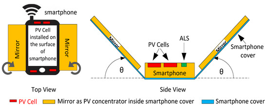
Figure 2.
Using mirrors as solar concentrators to enhance the incident light on PV cells.
Harvesting energy for both indoor and outdoor environments requires the use of two types of solar cells optimized for each lighting condition [56]. A smartphone cover has a large enough area to occupy two types of PV cells, a miniaturized electronic circuit, and a small capacity battery, which will increase the thickness of the cover sheet to some extent. This will enable the traditional circuit presented in Figure 1 to be feasible and efficient enough to recharge the smartphone’s battery to a certain level.
The monocrystalline PV cell used for this design is model no. KXOB22-04 × 3 L (IXYS), it can be used for both indoor and outdoor applications, and the rectangular-shaped cell has a size of 22 × 7 × 1.8 mm3. The solar cell has an open-circuit voltage of 1.89 V and a short circuit current of 15 mA, and typical efficiency of 22% at standard testing values of λ = 1000 W/m2 and 25 °C temperature, which is much higher than actual room lighting conditions. A total of four PV cells were used: two cells were connected in series to achieve a higher voltage, and then connected in parallel with two series-connected cells. A single power management circuit was used because small sized cells were used, and they were all expected to be in similar light conditions. Furthermore, using a chip with each solar cell increases the total power dissipation, lowering overall efficiency and requiring more space. The BQ25504 ultra-low-power boost converter for power management and working in a fractional open circuit voltage algorithm for MPPT was used [57].
4. Experimentation and Testing
To test the proposed system presented in Figure 2 for directly charging the smartphone battery, the PV cell has to charge the high-capacity smartphone internal battery. The battery’s open-circuit voltage was measured as compared to the battery status shown by the two tested smartphone models (commercially available, LG-F180K and SHW-M420S) in Figure 3. With the four PV cells used, it will take about 8 h at 2500 lx lighting conditions to recharge the battery from 1% to 10% battery status, so that the smartphone can be powered up and some emergency phone calls can be made, as shown in simulated graphs in Figure 3. Both smartphone model batteries were different and have different voltages, thus, we compared them using the battery status displayed on the smartphones as shown in Figure 3. Furthermore, to validate and analyze the solar energy harvesting technique, four Type-1 PV cells, similar to PV on a smartphone’s top surface, were installed on a normal wristwatch, as shown in Figure 4.
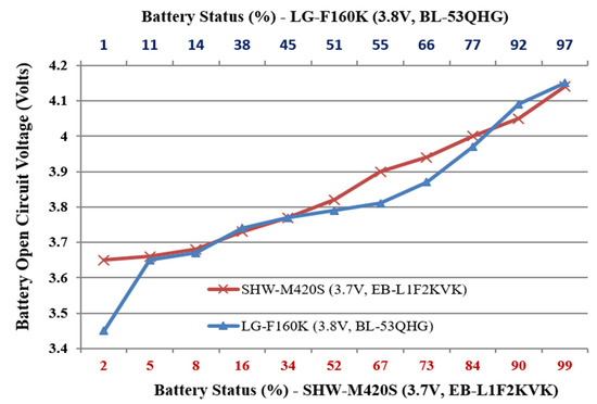
Figure 3.
Two smartphones’ battery voltage w.r.t displayed battery status.
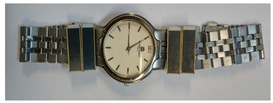
Figure 4.
Four Type-1 PV cells were fitted on this wristwatch for light energy harvesting.
Furthermore, for testing the system presented in Section 3, the commercial smartphone models LG-F160K and SHW-M420S with internal ALS sensors were used. We did not calibrate the sensor, and the error of the ALS sensor was found by comparing values with a TES-1330A light meter under different indoor lighting conditions, as shown in Figure 5. Under very close distances from the cathode fluorescent bulb (CFL), the maximum light intensity of 2500 lx was found in an office environment.
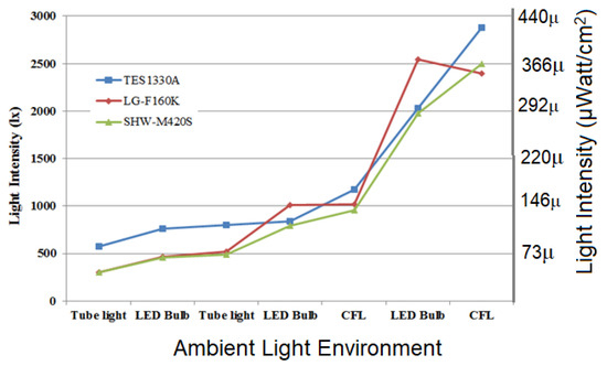
Figure 5.
A comparison of smartphone internal ALS data vs. light meter data.
The system for using a smartphone cover as a solar concentrator shown in Figure 2 was experimentally developed, as shown in Figure 6. By manually adjusting both mirror angles at the same magnitude, θ, the light intensity from the smartphone’s internal ALS sensor was compared with the reference light meter and open-circuit voltage of the four PV cells, as shown in Figure 7.
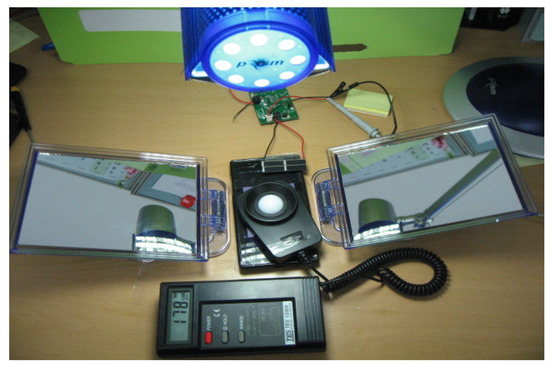
Figure 6.
The experimental platform for the solar concentrator system with an angled (θ) setup.
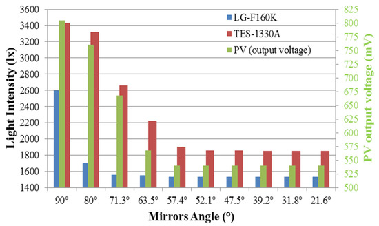
Figure 7.
Light intensity and PV output voltage variations due to changes in mirror angle θ.
The main objective of this experiment was to use the internal ALS sensor data as an input for the maximum power point calculation. However, due to its location inside the smartphone, the ALS was only able to estimate CFL light intensity at angles greater than 80°, making it impossible to use with MPPT. Therefore, to attain the maximum power point while using a smartphone cover as a solar concentrator, open-circuit voltage or resistive set-point techniques are more practical, where the former will occupy less space without reference resistors.
The solar concentrator was able to enhance the light intensity by about 1.85 and 1.43 times at angles of 90° and 71°, respectively, so that more ambient light energy could be harvested at 2500 lx light intensity in a typical office environment.
For the idea presented in Section 3, to attain maximum light energy harvesting, the optimum place is on the top of the smartphone cover where a maximal area is available for PVs. Two types of PV were used in this scheme as shown in Figure 8; one was four PV cells (Type-1) as previously discussed, and another was low-cost polycrystalline 60 × 65 mm2 with 15% efficiency (Type-2). The two types of PV have different output voltage levels. For maximum power harvesting, each requires a separate controller and converter. The rest of the available space was used for a small 3.7 V, 160 mAh, 31 × 24 × 2.9 mm3 Li-Polymer battery. The Type-1 PV cells were able to charge the additional battery via BQ25504-EVM under 2500 lx lighting intensity in an indoor office environment over 8 h. The Type-2 cells also charged the same battery in 8 h.
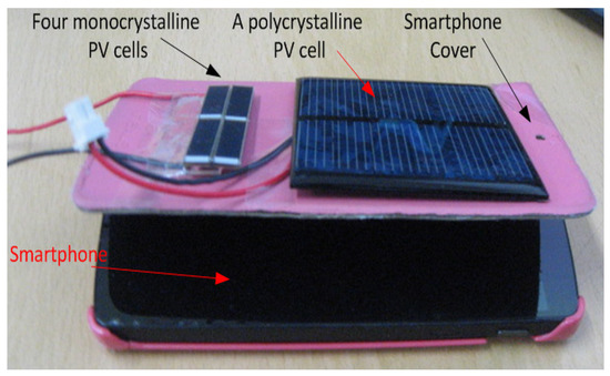
Figure 8.
The experiential platform for charging the small Li-Ion 3.7 V battery for emergency backup, using PVs on a smartphone cover.
To demonstrate that light energy harvesting can support the power required for some critical operations of the smart devices, as shown in the system proposed in Figure 1, an experimental platform as shown in Figure 9 was developed. Four Type-1 PV cells were fitted on a wristwatch and smartphone surfaces, and using the BQ25504 power management module, electrical power was harvested under different light conditions. The harvested energy was stored in the capacitor then transferred using a switch to a ZigBee green power module (MeshBee). ZigBee modules are frequently used in smart and wearable devices. Whenever the storage capacitor inside BQ25504-EVM had sufficient energy, the changeover switch was used to utilize the harvested energy for ZigBee data transmission.

Figure 9.
The testing scheme for powering the load during ZigBee communication, using light energy harvesting.
5. Discussion
We utilized a smartphone cover as a solar concentrator to enhance harvested light energy. The low-output harvested energy was studied as a supplement to primary battery power in order to perform some essential functions such as wireless communication. The presented scheme can be used in a variety of IoT nodes and wearables in the distant future [50,51] in home networking environments. Using both indoor and outdoor lighting conditions, a primary smartphone battery can be recharged using an energy harvesting technique with operating system (OS) support, where emergency calls and functions can be activated under a time limit. The energy harvested is discussed to show that when PV technology efficiency will reach a critical efficiency point, it will be able to support the functionality of smart devices with current load circuitry.
In order to show efficiency, we first connected two solar cells in series. Then, two pairs were connected in parallel to form four PV cells, as shown in Figure 9. The four solar cells were connected with the BQ25504-EVM circuit board and tested in different light conditions, as shown in Figure 10, with the energy generated harvested in the 100 µF capacitors. Within about 42 s of charging, inside a typical windowed office environment under different ambient light conditions, the combination of open windows with sunlight generated more power as compared to the electric lights only condition.
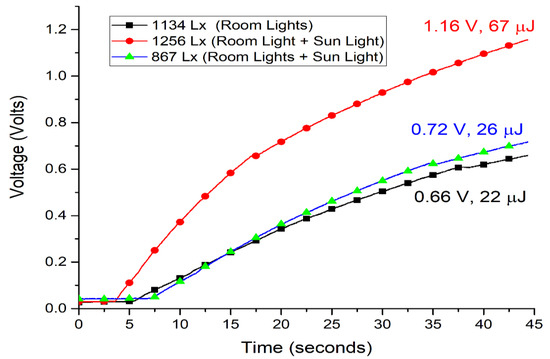
Figure 10.
Charging of the 100 uF capacitor by the BQ25504 converter under different light conditions (room light and hybrid light conditions).
As shown in Figure 10, the black line (i.e., room lights) showed charging in 42 s with only indoor room lights, and the blue line (i.e., room lights with sunlight) showed charging to a similar amount of power in the same amount of time. The red line (i.e., room lights with sunlight) made by combining these shows an increased amount of charge for 42 s when charging using indoor room lights and outdoor sunlight as a hybrid method. The hybrid method discussed here does not simply mean a mixture of room lights and sunlight, but is also the direction of the development of commercial products that can be highlighted as having the biggest advantage in this paper. It is natural that cells vary depending on the angle that they receive light from, and in order to develop this more scientifically in the future, ideal hybrid methodology must be adopted in conjunction with an optimal angle.
Using the testing scheme in Figure 9, a 147 µF capacitor was connected to the output of the BQ25504 circuitry board. After charging the capacitor, the VBAT_OK signal was used to supply the energy from the storage capacitor to the ZigBee module. Initially, the capacitor charged to 2.8 V (576 µJ), as shown in Figure 11. This energy was enough to bear the inrush current, initialization, and data transmission of the module. After first-time data transmission, the capacitor voltage varied from 1.8 V, the lower limit of the under-voltage-lockout circuit, to 2.8 V, repeatedly. Thus subsequent data transmission requires less energy (338 µJ) as compared to the first-time power-up procedure of the ZigBee module.
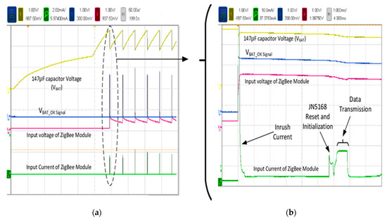
Figure 11.
Charging of the 147 µF capacitors by the BQ25504 converter under 1200 lx room light conditions to power the ZigBee module: (a) a screenshot of the test, (b) a zoomed-in screenshot of the test.
6. Conclusions
In this work, an energy management system including an ambient light energy harvesting method is proposed, where different schemes are shown, utilizing PV cells to share battery power consumption and to supplement it. Obtaining ambient light energy and its intensity data can result in the viability of utilizing light energy harvesting technology in low-power consumption devices. A novel scheme of utilizing solar concentrators in smartphones is presented to enhance light energy harvesting in the smartphone. The small sized PVs cannot power up the smartphone, but can be used in an emergency scenario. It is shown that PV can share battery consumption in smartphones, wearables, and IoT devices by powering the small low-power logic and algorithm of the smart wearable device. The PV cells used for this research were very small in size (a size of 22 × 7 × 1.8 mm3), had an open-circuit voltage of 1.89 V and a short circuit current of 15 mA, and a typical efficiency of 22% at standard testing values of λ = 1000 W/m2 and 25 °C temperature. A total of four PV cells were used: two cells were connected in series to achieve a higher voltage and were then connected in parallel with two series-connected cells.
It is also shown that the power-up sequence of the smartphone can be altered by changing different settings in the operating system (OS) in order to keep power consumption at a minimum. This will help in developing a low-energy mode with a basic function to make emergency calls and conserve battery in critical situations when no other source of battery recharging is available.
Currently available PV technology is advancing in terms of efficiency, size, and structural flexibility. Though the scheme presented in this paper is not yet viable, future advancements in PV technology, along with algorithm improvements, can lead to its integration in smart devices, as circuits and other required component technologies are available and can be tuned easily for its application.
Author Contributions
H.J. developed the stimuli and interpreted the results; T.J. conducted the model’s data analysis and led the project. All authors have read and agreed to the published version of the manuscript.
Funding
This work was supported by a research grant from Hallym University, HRF-202106-010.
Institutional Review Board Statement
Not applicable.
Informed Consent Statement
Not applicable.
Data Availability Statement
The data presented in this study are available on request from the author.
Conflicts of Interest
The authors declare no conflict of interest.
References
- Poon, C.; Lo, B.; Yuce, M.; Alomainy, A.; Hao, Y. Body Sensor Networks: In the Era of Big Data and Beyond. IEEE Rev. Biomed. Eng. 2015, 8, 4–16. [Google Scholar] [CrossRef] [PubMed]
- Selvan, K.V.; Ali, M.S.M. Micro-scale energy harvesting devices: Review of methodological performances in the last decade. Renew. Sustain. Energy Rev. 2016, 54, 1035–1047. [Google Scholar] [CrossRef]
- Shaikh, F.K.; Zeadally, S. Energy harvesting in wireless sensor networks: A comprehensive review. Renew. Sustain. Energy Rev. 2016, 55, 1041–1054. [Google Scholar] [CrossRef]
- Brito-Rojas, J.A.; Aguilar-Calderon, J.A.; Garcia-Sanchez, O.; Tripp-Barba, C.; Zaldivar-Colado, A.; Misra, S. A low-cost solar cell charger prototype for smartphone’s battery charging. In Proceedings of the Adaptive Science & Technology (ICAST), 2014 IEEE 6th International Conference, Ota, Nigeria, 29–31 October 2014; pp. 1–5. [Google Scholar]
- Park, J.; Joshi, H.; Lee, H.G.; Kiaei, S.; Ogras, U.Y. Flexible PV-cell Modeling for Energy Harvesting in Wearable IoT Applications. ACM Trans. Embed. Comput. Syst. 2017, 16, 1–20. [Google Scholar] [CrossRef]
- Jokic, P.; Magno, M. Powering smart wearable systems with flexible solar energy harvesting. In Proceedings of the 2017 IEEE International Symposium on Circuits and Systems (ISCAS), Baltimore, MD, USA, 28–31 May 2017; pp. 1–4. [Google Scholar] [CrossRef]
- Ferreira, D.; Schuss, C.; Luo, C.; Goncalves, J.; Kostakos, V.; Rahkonen, T. Indoor light scavenging on smartphones. In Proceedings of the 15th International Conference on Mobile and Ubiquitous Multimedia, Rovaniemi, Finland, 12–15 December 2016; pp. 369–371. [Google Scholar]
- Rong, G.; Zheng, Y.; Sawan, M. Energy Solutions for Wearable Sensors: A Review. Sensors 2021, 21, 3806. [Google Scholar] [CrossRef]
- Iyer, V.; Bayati, E.; Nandakumar, R.; Majumdar, A.; Gollakota, S. Charging a Smartphone Across a Room Using Lasers. Proc. ACM Interact. Mob. Wearable Ubiquitous Technol. 2018, 1, 1–21. [Google Scholar] [CrossRef]
- Liu, Y.; Qin, Z.; Zhao, C. Autocharge: Automatically Charge Smartphones Using a Light Beam. 2015. Available online: https://www.microsoft.com/en-us/research/wp-content/uploads/2016/02/AutoCharge-TR.pdf (accessed on 14 February 2022).
- Kumar, N.; Agrawal, A.; Khan, R.A. Smartphone with Solar Charging Mechanism to Issue Alert during Rainfall Disaster. In International Conference on Recent Developments in Science, Engineering and Technology; Springer: Berlin/Heidelberg, Germany, 2017; pp. 442–449. [Google Scholar] [CrossRef]
- Jain, N.; Fan, X.; Leon-Salas, W.D.; Lucietto, A.M. Extending battery life of smartphones by overcoming idle power consumption using ambient light energy harvesting. In Proceedings of the 2018 IEEE International Conference on Industrial Technology (ICIT), Piscataway, NJ, USA, 20–22 February 2018; pp. 978–983. [Google Scholar] [CrossRef]
- Michaels, H.; Benesperi, I.; Freitag, M. Challenges and prospects of ambient hybrid solar cell applications. Chem. Sci. 2021, 12, 5002–5015. [Google Scholar] [CrossRef] [PubMed]
- Apostolou, G.; Reinders, A.H.M.E. Overview of Design Issues in Product-Integrated Photovoltaics. Energy Technol. 2014, 2, 229–242. [Google Scholar] [CrossRef]
- Gurung, A.; Qiao, Q. Solar charging batteries: Advances, challenges, and opportunities. Joule 2018, 2, 1217–1230. [Google Scholar] [CrossRef] [Green Version]
- Schuss, C.; Eichberger, B.; Rahkonen, T. Design specifications and guidelines for efficient solar chargers of mobile phones. In Proceedings of the Multi-Conference on Systems, Signals & Devices (SSD), 2014 11th International, Castelldefels-Barcelona, Spain, 11–14 February 2014; pp. 1–5. [Google Scholar] [CrossRef]
- Schuss, C.; Rahkonen, T. Photovoltaic (PV) energy as recharge source for portable devices such as mobile phones. In Proceedings of the 2012 12th Conference of Open Innovations Association (FRUCT), Oulu, Finland, 5–9 November 2012. [Google Scholar]
- Kline, M.; Izyumin, I.; Boser, B.; Sanders, S. Capacitive power transfer for contactless charging. In Proceedings of the 2011 Twenty-Sixth Annual IEEE Applied Power Electronics Conference and Exposition (APEC), Fort Worth, TX, USA, 6–11 March 2011; pp. 1398–1404. [Google Scholar]
- Nasiri, A.; Zabalawi, S.A.; Mandic, G. Indoor Power Harvesting Using Photovoltaic Cells for Low-Power Applications. IEEE Trans. Ind. Electron. 2009, 56, 4502–4509. [Google Scholar] [CrossRef]
- Wang, W.S.; O’Donnell, T.; Wang, N.; Hayes, M.; O’Flynn, B.; O’Mathuna, C. Design considerations of sub-mw indoor light energy harvesting for wireless sensor systems. ACM J. Emerg. Technol. Comput. Syst. (JETC) 2010, 6, 1–26. [Google Scholar] [CrossRef]
- Ma, X.; Bader, S.; Oelmann, B. Power Estimation for Indoor Light Energy Harvesting Systems. IEEE Trans. Instrum. Meas. 2020, 69, 7513–7521. [Google Scholar] [CrossRef]
- Ma, X.; Bader, S.; Oelmann, B. Estimating Harvestable Energy in Time-Varying Indoor Light Conditions. In Proceedings of the 8th International Workshop on Energy Harvesting and Energy-Neutral Sensing Systems, Virtual Event, Japan, 16–19 November 2020; pp. 71–76. [Google Scholar]
- Yang, C.; Xue, R.; Li, X.; Zhang, X.; Wu, Z. Power performance of solar energy harvesting system under typical indoor light sources. Renew. Energy 2020, 161, 836–845. [Google Scholar] [CrossRef]
- Brogan, Q.; O’Connor, T.; Ha, D.S. Solar and thermal energy harvesting with a wearable jacket. In Proceedings of the 2014 IEEE International Symposium on Circuits and Systems (ISCAS), Melbourne, Australia, 1–5 June 2014; pp. 1412–1415. [Google Scholar] [CrossRef]
- Scalia, A.; Bella, F.; Lamberti, A.; Bianco, S.; Gerbaldi, C.; Tresso, E.; Pirri, C.F. A flexible and portable powerpack by solid-state supercapacitor and dye-sensitized solar cell integration. J. Power Sources 2017, 359, 311–321. [Google Scholar] [CrossRef]
- Chen, H.-L.; Cattoni, A.; De Lépinau, R.; Walker, A.W.; Höhn, O.; Lackner, D.; Siefer, G.; Faustini, M.; Vandamme, N.; Goffard, J.; et al. A 19.9%-efficient ultrathin solar cell based on a 205-nm-thick GaAs absorber and a silver nanostructured back mirror. Nat. Energy 2019, 4, 761–767. [Google Scholar] [CrossRef]
- Biswas, S.; Kim, H. Solar Cells for Indoor Applications: Progress and Development. Polymers 2020, 12, 1338. [Google Scholar] [CrossRef] [PubMed]
- Li, B.; Hou, B.; Amaratunga, G.A. Indoor photovoltaics, The Next Big Trend in solution-processed solar cells. InfoMat 2021, 3, 445–459. [Google Scholar] [CrossRef]
- Liu, C.-Y.; Huang, C.-K.; Huang, Y.-Y.; Chang, K.-C.; Yu, K.-L.; Chiang, C.-H.; Wu, C.-G.; Lee, S.-C.; Yen, W.-Y.; Sheu, J.-K.; et al. Flexible multijunction solar cells embedded inside smart dust modules for outdoor applications to Smart Grids. Appl. Energy 2021, 306, 117970. [Google Scholar] [CrossRef]
- Devadiga, D.; Selvakumar, M.; Shetty, P.; Santosh, M.S. Dye-Sensitized Solar Cell for Indoor Applications: A Mini-Review. J. Electron. Mater. 2021, 50, 3187–3206. [Google Scholar] [CrossRef]
- Saeed, M.A.; Yoo, K.; Kang, H.C.; Shim, J.W.; Lee, J.-J. Recent developments in dye-sensitized photovoltaic cells under ambient illumination. Dye Pigments 2021, 194, 109626. [Google Scholar] [CrossRef]
- Hashemi, S.A.; Ramakrishna, S.; Aberle, A.G. Recent progress in flexible–wearable solar cells for self-powered electronic devices. Energy Environ. Sci. 2020, 13, 685–743. [Google Scholar] [CrossRef]
- Dauzon, E.; Sallenave, X.; Plesse, C.; Goubard, F.; Amassian, A.; Anthopoulos, T.D. Pushing the Limits of Flexibility and Stretchability of Solar Cells: A Review. Adv. Mater. 2021, 33, 2101469. [Google Scholar] [CrossRef]
- Jeong, T. Time-series Data Classification and Analysis associated with Machine Learning Algorithms for Cognitive Perception and Phenomenon. IEEE Access 2020, 8, 222417–222428. [Google Scholar] [CrossRef]
- Jagadamma, L.K.; Wang, S. Wide-Bandgap Halide Perovskites for Indoor Photovoltaics. Front. Chem. 2021, 9, 632021. [Google Scholar] [CrossRef]
- You, Y.-J.; Saeed, M.A.; Shafian, S.; Kim, J.; Kim, S.H.; Kim, S.H.; Kim, K.; Shim, J.W. Energy recycling under ambient illumination for internet-of-things using metal/oxide/metal-based colorful organic photovoltaics. Nanotechnology 2021, 32, 465401. [Google Scholar] [CrossRef]
- Saeed, M.A.; Kim, S.H.; Baek, K.; Hyun, J.K.; Lee, S.Y.; Shim, J.W. PEDOT: PSS: CuNW-based transparent composite electrodes for high-performance and flexible organic photovoltaics under indoor lighting. Appl. Surf. Sci. 2021, 567, 150852. [Google Scholar] [CrossRef]
- Wang, K.-L.; Zhou, Y.-H.; Lou, Y.-H.; Wang, Z.-K. Perovskite indoor photovoltaics: Opportunity and challenges. Chem. Sci. 2021, 12, 11936–11954. [Google Scholar] [CrossRef]
- Schuss, C.; Leikanger, T.; Eichberger, B.; Rahkonen, T. Efficient use of solar chargers with the help of ambient light sensors on smartphones. In Proceedings of the Open Innovations Association (FRUCT16), 2014 16th Conference, Oulu, Finland, 27–31 October 2014; pp. 79–85. [Google Scholar] [CrossRef]
- Sarik, J.; Kim, K.; Gorlatova, M.; Kymissis, I.; Zussman, G. More than meets the eye—A portable measurement unit for characterizing light energy availability. In Proceedings of the Global Conference on Signal and Information Processing (GlobalSIP), Austin, TX, USA, 3–5 December 2013; pp. 387–390. [Google Scholar] [CrossRef]
- Sharma, R.; Balaji, S. A Tour into Ambient Energy Resources and Battery Optimization. In Proceedings of the Signal and Image Processing (ICSIP), 2014 Fifth International Conference, Bangalore, India, 8–10 January 2014; pp. 343–347. [Google Scholar]
- Rezzi, F.; Collamati, L.; Costagliola, M.; Cutrupi, M. Battery management in mobile devices. In Frequency References, Power Management for SoC, and Smart Wireless Interfaces; Springer: Berlin/Heidelberg, Germany, 2014; pp. 147–168. [Google Scholar]
- Ta, T.; Baras, J.S.; Zhu, C. Improving smartphone battery life utilizing device-to-device cooperative relays underlaying LTE networks. In Proceedings of the Communications (ICC), 2014 IEEE International Conference, Sydney, Australia, 10–14 June 2014; pp. 5263–5268. [Google Scholar] [CrossRef] [Green Version]
- Leonov, V. Energy Harvesting for Self-Powered Wearable Devices. In Wearable Monitoring Systems; Springer: Berlin/Heidelberg, Germany, 2011; pp. 27–49. [Google Scholar] [CrossRef]
- Tan, Y.K.; Koh, W.S. Wearable Energy Harvesting System for Powering Wireless Devices; Intech Open Limited: London, UK, 2011. [Google Scholar]
- Toh, W.Y.; Tan, Y.K.; Koh, W.S.; Siek, L. Autonomous Wearable Sensor Nodes with Flexible Energy Harvesting. IEEE Sens. J. 2014, 14, 2299–2306. [Google Scholar] [CrossRef]
- Leonov, V.; Van Hoof, C.; Vullers, R.J. Thermoelectric and Hybrid Generators in Wearable Devices and Clothes. In Proceedings of the Wearable and Implantable Body Sensor Networks, Sixth International Workshop, Washington, DC, USA, 3–5 June 2009; pp. 195–200. [Google Scholar] [CrossRef]
- MacKenzie, J.D.; Ho, C. Perspectives on Energy Storage for Flexible Electronic Systems. Proc. IEEE 2015, 103, 535–553. [Google Scholar] [CrossRef]
- Wagner, D.T.; Rice, A.; Beresford, A.R. Device Analyzer: Understanding Smartphone Usage. Mobile and Ubiquitous Systems: Computing, Networking, and Services; Springer: Berlin/Heidelberg, Germany, 2014; pp. 195–208. [Google Scholar] [CrossRef] [Green Version]
- Upton, J.F.; Stein, S.L. Responder Technology Alert Monthly (Oct–Nov 2014); Pacific Northwest National Laboratory (PNNL): Richland, WA, USA, 2015. [Google Scholar] [CrossRef]
- Roblek, V.; Meško, M.; Krapež, A. A Complex View of Industry 4.0. SAGE Open 2016, 6. [Google Scholar] [CrossRef] [Green Version]
- Kadirvel, K.; Carpenter, J. Self-Powered, Ambient Light Sensor Using bq25504. Texas Instruments. January 2012. Available online: https://www.ti.com/lit/an/slua629a/slua629a.pdf?ts=1644926348033&ref_url=https%253A%252F%252Fwww.google.com%252F (accessed on 14 February 2022).
- López, M.T.P.; Penella, M.T.; Gasulla, M. A New MPPT Method for Low-Power Solar Energy Harvesting. IEEE Trans. Ind. Electron. 2009, 57, 3129–3138. [Google Scholar] [CrossRef] [Green Version]
- Jabbar, H.; Song, Y.S.; Jeong, T. RF energy harvesting system and circuits for charging of mobile devices. IEEE Trans. Cons. Electron. 2010, 56, 247–253. [Google Scholar] [CrossRef]
- Gupta, M.; Koc, A.T.; Vannithamby, R. Analyzing mobile applications and power consumption on smartphone over LTE network. In Proceedings of the Energy Aware Computing (ICEAC), 2011 International Conference, Istanbul, Turkey, 30 November–2 December 2011; pp. 1–4. [Google Scholar] [CrossRef]
- Nelson, A.; Schmandt, J.; Wilkins, W.; Parkerson, J.P.; Banerjee, N. System support for micro-harvester powered mobile sensing. In Proceedings of the Real-Time Systems Symposium (RTSS), 2013 IEEE 34th, Vancouver, BC, Canada, 30 January 2013; pp. 258–267. [Google Scholar] [CrossRef]
- Lu, C.; Raghunathan, V.; Roy, K. Maximum power point considerations in micro-scale solar energy harvesting systems. Proceedings of 2010 IEEE International Symposium on Circuits and Systems, Paris, France, 30 May–2 June 2010; pp. 273–276. [Google Scholar] [CrossRef]
Publisher’s Note: MDPI stays neutral with regard to jurisdictional claims in published maps and institutional affiliations. |
© 2022 by the authors. Licensee MDPI, Basel, Switzerland. This article is an open access article distributed under the terms and conditions of the Creative Commons Attribution (CC BY) license (https://creativecommons.org/licenses/by/4.0/).