Article

Advanced Technologies Used in Digitizing the Cultural Heritage of Northwestern Colchis: The Experience of the Markul Expedition

1
Institute of Archaeology of the Russian Academy of Sciences, 117292 Moscow, Russia
2
Federal Research Centre the Subtropical Scientific Centre of the Russian Academy of Sciences, 354000 Sochi, Russia
3
Faculty of Engineering and Ecology, Sochi State University, 354000 Sochi, Russia
4
Moscow Secondary School 171, 119270 Moscow, Russia
5
N.N. Semenov Federal Research Center of Chemical Physics Russian Academy of Sciences, 119334 Moscow, Russia
*
Author to whom correspondence should be addressed.
Appl. Sci. 2022, 12(4), 2052; https://doi.org/10.3390/app12042052
Submission received: 26 December 2021 / Revised: 9 February 2022 / Accepted: 14 February 2022 / Published: 16 February 2022
(This article belongs to the Special Issue Advanced Technologies in Digitizing Cultural Heritage)

Abstract

:
The article presents the experience of the Institute of Archeology of the Russian Academy of Science’s Markul Expedition, which utilized digital technologies for the study, preservation, and popularization of cultural heritage. The objective of the Markul Expedition was to obtain a complete picture of the historical and cultural landscape of Northwestern Colchis in antiquity by applying two key digital technologies: geographic information systems (GIS) and photogrammetry. The results obtained from the latter were used both independently and were integrated into GIS as separate layers (orthophotomaps, digital terrain models) or as hyperlinks to objects (3D models, videos, plans, sections, etc.). The objects investigated by the expedition are very diverse both in size and in terms of shooting conditions. Accordingly, each category of archaeological site required an individual approach, and a separate methodology and equipment. The final visualization angles differ to a fair extent from the original samples even though photogrammetry provides more accurate results than manual measurements. There are several reasons for this, including the vegetation, which is a dominant factor in the Caucasus subtropical area and led to partial visual distortions of the photographed objects. For this reason, the final projections of architectural forms required corrections and some hand drawing. In this process, new aspects appeared in the final result, resulting from the archaeologist and artist’s differing views of the objects. Our experience of using modern remote sensing technologies is also presented in the article.

1. Introduction

The challenge to digitalize cultural heritage data has long been a focus of interest. Digitalization has become an important step in the development of civilization as a whole, and this is also the case in the humanities. Over the last few years, this has become crucial due to the COVID-19 pandemic restrictions. Museums and cultural institutions advanced at a faster pace [1,2] as compared to archaeological expeditions. However, the submission requirements for reports and documentation are also changing under the new circumstances. The preservation of information in digital form, including artifacts and field findings, has become vital to avoid them being lost, e.g., artifacts can be destroyed and reports can be damaged by fire. Regrettably, such incidents have occurred in history. Moreover, excavations themselves can cause damage to a site, leading to the information being saved but the heritage object being ruined. Therefore, it is essential to keep any information in a comprehensive visual form. The most convenient way of achieving this is by presenting materials in 3D format with a geographic reference to the terrain. The most favorable approaches are laser scanning and photogrammetry, with the latter becoming increasingly widespread due to its availability and low cost [3,4,5,6,7]. This article presents the work of the Institute of Archeology of the Russian Academy of Sciences’ Markul Expedition, which conducted research in the Northwestern Colchis (the Greater Sochi Region of the Russian Federation and the Republic of Abkhazia) using a combination of digital technologies in order to recreate a holistic picture of the historical and cultural landscape of this territory in antiquity (Figure 1). In ancient times, Northwestern Colchis played an essential role in the interaction between the ancient world and the world of barbarian tribes. The history of the region is “antique-centrist” according to the available ancient written data; however, archaeologically, this territory has only been studied fragmentarily, without generalizations or attempts to evaluate the role of the local population. Therefore, the work of the Markul Expedition aimed at filling this gap in knowledge.
The expedition had two main objectives: to create a complete geographic information system (GIS) of the archaeological sites in the region and to study the Markul settlement [7], which is a unique local population site that has been virtually untouched by anthropogenic activity, and thus reflects the history of the region from the 4th century BC to the 14th century A.D. This site is located in the Ochamchira region of the Republic of Abkhazia, 10 km inland from the coast.

2. Materials and Methods

The Markul Expedition used two main digital technologies: geographic information systems (GIS) and photogrammetry. The results of the latter were additionally integrated into the GIS, i.e., a technology for integrating factual electronic databases (text, digital, etc.) and geo-images. Simultaneously, an important feature of any modern GIS is the option for continuous expansion by adding new layers and connecting new databases [8].
Archaeological research in the territory of Abkhazia, which aimed at forming a GIS of archaeological sites, was started by the Institute of Archeology, RAS, in 2001 and now includes 1780 objects, including dolmens, temples, fortresses, settlements, and burial grounds; however, there are no architectural remains above the surface of the earth. The Markul Archaeological Expedition used ArcMap in the work. Data obtained from the public domain in 2009 ASTER GDEM were used as the basic geographic layers. In addition, 1:100,000 and 1:250,000 scale geographical and topographic maps, which cover most of the coastal area, and vector data derived from raster topographic maps were utilized. GPS coordinates of archaeological sites were found in the course of field studies of the territory (Figure 2).
The primary database of archaeological sites contains the following main items:
  • Title.
  • Type of site.
  • Ancient (antique or local) place name (if any).
  • Link to mention in sources (if any).
  • Bibliography (if any).
  • Names of researchers of the site (if researched).
  • Years of study of the site (if researched).
  • Description of the site.
  • Level of preservation.
  • Modern use of the territory.
  • Area (if defined).
  • Dating.
  • Interpretation.
Because the level of preservation and research of sites differ, the primary database was constantly updated by applying layering and hyperlinks. Some of the most crucial layers of information are the filmed orthophotomaps of settlements and 3D models of sites. Concerning the Markul settlement, stationary studies, some of which have been conducted by our expedition since 2014, and photogrammetric models of excavations and individual artifacts were added to the GIS (Figure 3).
In a broad sense, photogrammetry is a technical discipline that creates a 3D image of an object from a series of digital photographs, which allow one to record the current state, measure geometric characteristics (dimensions, areas, and volumes), study textures, and obtain all the necessary drawings, projections, and cuts. Photogrammetry methods were applied in archeology even in the pre-digital era and were mainly associated with the analysis of aerial photography materials [3]. The development of computer technology gave a powerful stimulus to the development of photogrammetry methods and made it possible to automate image processing using a personal computer, which increased its availability and significantly expanded the limits of the technology. In the last decade, as a result of the development of computer resources, photogrammetry has become widespread in field archeology, museums, architecture, restoration, and other scientific areas and applied activities related to the preservation of cultural heritage sites. In the Markul Expedition’s work, photogrammetry has been applied since 2017 and has become an integral part of the work, complementing the classical methods of documentation [9,10,11]. Alongside the immediate aim of providing additional information on sites, and thus filling the GIS databases with the help of photogrammetry, the expedition members were required to create methods to be used with various types of archaeological objects.
The objects investigated by the expedition are very diverse, i.e., they differ from each other both in size and in terms of shooting conditions. Accordingly, each category of archaeological site required an individual approach, methodology, and equipment. Conventionally, we can divide all types of objects into three groups depending on their size:
large, e.g., fortifications, architectural complexes, ancient settlements, etc.;
medium, e.g., excavations, architectural structures (temples, fortifications such as towers, sections of walls);
small, e.g., artifacts, architectural details, and other similar elements that can be transported to a photography studio with convenient shooting and lighting conditions.

3. Results and Discussion

During the expedition, all groups of objects were studied.
Photogrammetry of Large Object: As a result of the mountainous terrain and subtropical vegetation, UAVs were used in order to obtain accurate plans of the settlements and to study the design of large temple complexes and fortresses. This required us to develop photogrammetry methods for this purpose.
The photogrammetry of such objects is divided into two tasks:
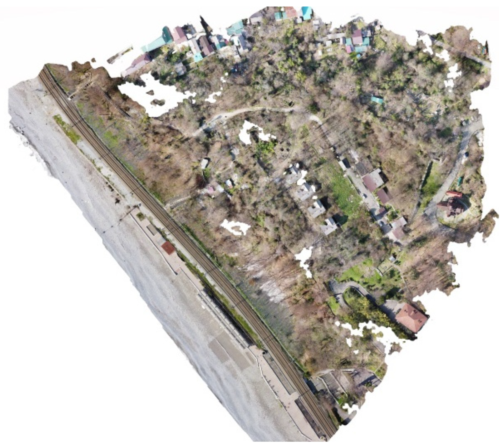
receiving an orthophotomap of an object;
obtaining a detailed 3D model.
The orthophotomap of the Markul settlement was obtained by our expedition in 2019, which made it possible to map the territory and to create a digital elevation model (DEM) (Figure 4) [12].
The method for obtaining an orthophotomap of an archaeological object is very similar that of a usual geodetic survey using a UAV, which involves shooting at a 90° angle to the horizon [13].
We found that shooting is the most effective when:
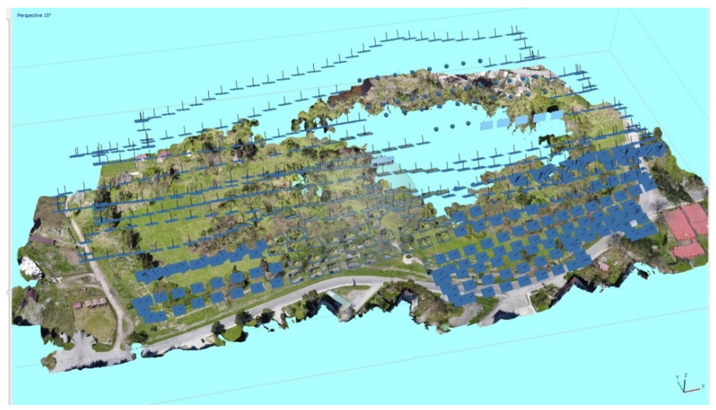
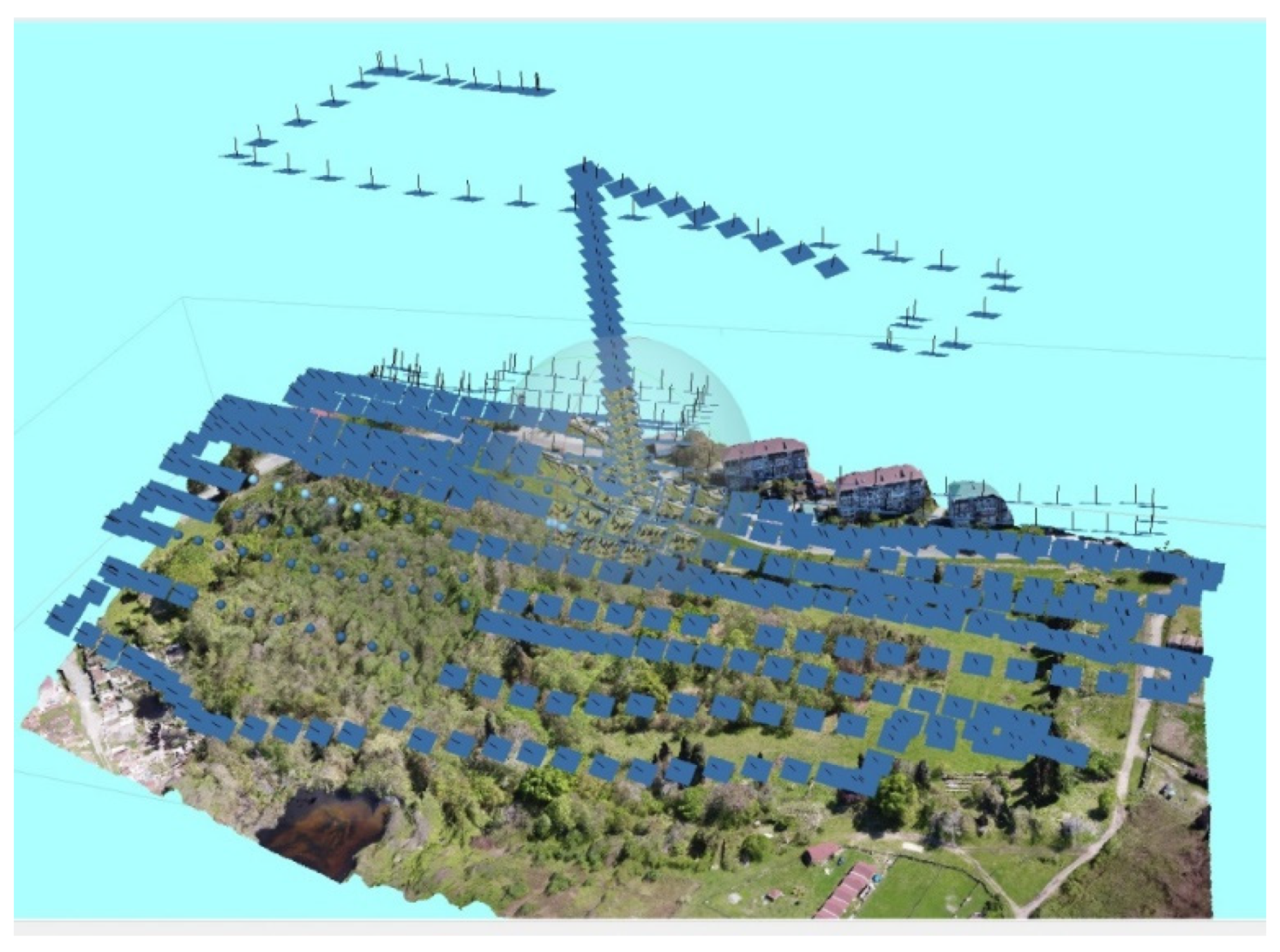
the flight height of the drone is approximately 15 m;
the overlap of adjacent frames is 60–80%;
the camera is tilted 90° to the horizon.
This photogrammetry method was tested over the remains of the Godlik fortress (Lazarevsky district of Sochi, Figure 2, No.1). The drone used was a DJI Mavic Mini with a 12 Mpx camera. The flight height was 25 m due to the tall trees and buildings in the area of the fortress. The camera was set for automatic shooting at an interval of 2 s, and the trajectory and flight speed were selected to provide the necessary overlap of frames and create, if possible, a perpendicular grid of images. The tilt angle of the camera was set to 90° to the horizon (Figure 5).
Processing the shots showed that:
in vertical shooting, upright details, such as walls, etc., are not partially or fully shot, and the texture is heavily distorted or smeared on the final picture;
even in the absence of vegetation (shooting was carried out in February 2021), shooting vertically down through the crown of trees and bushes does not allow the surface of the earth, the fragments of walls, or fortress towers to be captured. In this scenario, it is nearly impossible to automatically determine the relevant points, which leads to the situation in which a series of pictures with trees are not recognized and deleted. When there are readable objects (the remains of a fortress wall, buildings, roads, open spaces with grass) and tree crowns, the pictures are easily recognized.
As a result, the fortress was only readable in areas that were free from vegetation in the processed orthophotomap, which made it impossible to build an entire plan of the fortification (Figure 6). Moreover, its contours were better estimated in the DEM (Figure 7).
On the basis of the analysis, it was decided to attempt tilted aerial photography to avoid the distortion of vertical details and to capture the earth’s surface under the crowns of trees. In order to avoid distortions, the shooting angle was adjusted to 60°. This technique was tested in the study of Pitiunt fortress (Pitsunda, Republic of Abkhazia, (Figure 2, No. 2) [14].
The fortress is located on a flat terrain and occupies an area of 150 × 230 m. The southern and western parts of the fortress wall and the inner territory of the fortress were free from dense vegetation, while the northern and eastern parts were heavily overgrown and in some places are in a swamp. The shooting interval was selected as 2 s, the flight altitude was 25 m due to the cypress trees inside the fortress, and the flight speed was selected to ensure a frame overlap of 60–80%. The flight trajectory was adjusted to “snake” along the E–W line over the entire area of the fortification, first from north to south, and then from south to north (Figure 8).
A processing analysis of the obtained material showed:
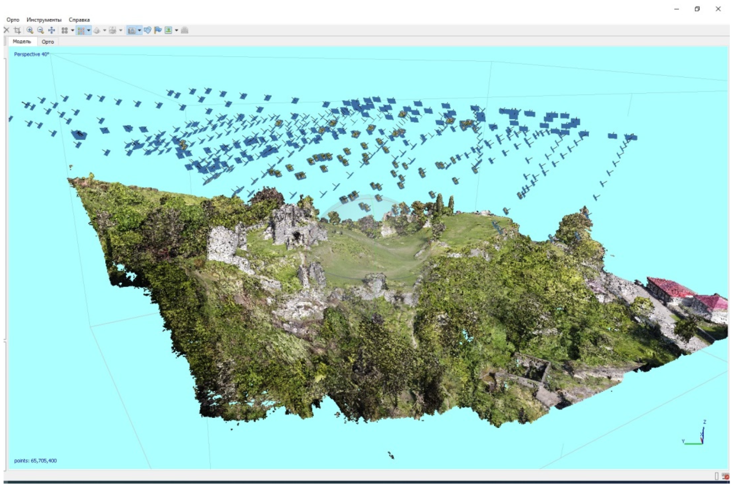
vertical objects, such as walls, towers, trees, etc., appeared in significantly better detail, and the texture was of acceptable quality;
the ground under single and sporadic trees was better displayed.
Nevertheless, the shots of the central part of the eastern fortification, which was overgrown with dense vegetation, did not match together and were not included in the estimation, since the pictures did not contain readable and easily recognizable objects. This was solved by including a series of shots taken from a height of 250 m in the estimation (Figure 9).
Dense vegetation in the territory of the eastern fortification, together with easily readable landmarks and details, such as roads, roofs of houses, etc., in the neighboring area, interfered with the picture and they were automatically recognized and included in the construction of the final 3D model. However, this resulted in an orthophotoplan with suitable characteristics, and thus provided us with a high-quality plan of the fortress and we were able to carry out the necessary measurements (Figure 10 and Figure 11).
Pitiunt fortress has no significant surviving structures, except for geometrically simple sections of walls and towers. When studying complex shapes, e.g., fortresses with well-preserved temples, shooting at an angle of 60° is not necessarily sufficient for a detailed study. Therefore, we decided to try shooting at obtuse angles when exploring Bzyb Fortress (Republic of Abkhazia, Figure 2, No. 3).
The fortress stands on a spur of a mountain ridge, and the territory had practically no trees and was covered with grass. In the upper part of the fortress, there is a well-preserved cross-domed three-apse 10th century temple, with preserved vestibule walls on the south, west, and north.
For a rigorous study of all the fortress walls, towers, and the temple from the outside and inside, shooting was carried out at a 45° angle to the horizon to obtain both the vertical and horizontal surfaces of the object with the same quality. The flight path was chosen, as in the previous example, as several contrasting “snaking” paths at different azimuths in order to photograph all the details of the fortress and not to leave any blind spots (Figure 12).
As a result, a good quality 3D model of the fortress was obtained without noticeable distortions, in addition to an orthophotoplan and DEM, allowing further processing, measurements, and research (Figure 13 and Figure 14).
The preliminary conclusions were as follows:
with a 90° camera angle the open objects only without significant vertical details can be photographed;
the more complex the object is geometrically, the more vertical details it contains, and so the more difficult it is to photograph. Preferably, a series of flights with shooting angles of 90°, 60°, and 45° is required. The flight path should be characterized by a series of oncoming “snakes” at several azimuths, depending on the geometry of the object.
the flight height should be adjusted according to the height of the surrounding obstacles;
the overlap of shots should be 60–80%;
in order to avoid unusable shots due to trees, if the area is heavily forested, it is necessary to shoot the area from a higher position.
The photogrammetric study examples of large objects using UAV aimed to show how to adjust shooting technology to dense subtropical vegetation conditions and to select suitable plans and flyby algorithms. Scaling and georeferencing of the resulting models was performed based on the drone’s built-in GPS module. The resulting accuracy was sufficient to submit a primary exploration documentation of the identified archaeological objects, which was one of the expedition’s objectives.
Photogrammetry of medium-sized stationary objects: included the architectural elements of the sites, the boundaries of excavations and pits, and small- and medium-sized temples, which constitutes the scale of photogrammetry utilized during the Markul expedition.
The Markul temple and the temple area (Figure 15), including the Alakhash-abaa tower (Figure 16), were filmed after the completion of excavations, which, in 2017, marked the beginning of the use of photogrammetry in this project. Three-dimensional models were obtained for both objects, and tower wall profiles were obtained from various projections. This made it possible to establish that the tower was built in the Roman style described in the works of Vitruvius [15].
Since 2017, the expedition has collected photogrammetry data from more than three dozen churches in Abkhazia and seven churches in Greater Sochi. Photogrammetry projections and sections were published in the first part of the document—a catalogue of late antique and medieval Christian churches in the North-Eastern Black Sea region [16].
Shooting of such objects is mainly carried out with a reflex camera. Several circuits are made around the object, successively changing the shooting height, i.e., from eye level, from raised hands, and from a tripod raised above your head. Shots are overlapped by 60–80%.
For small flat objects such as excavation boundaries, one circuit at one height, with a survey angle to the surface that is close to normal is usually sufficient. For temples, 3–4 circuits are usually required with a sequential change in the shooting height from 1.5 (eye level) to 3.5 m (the height of a tripod raised above the head) (Figure 17).
Because of the continuous nature of shooting, obtaining a 3D model of an object is generally not very challenging. The difficulty is the inaccessibility of shooting the upper part of the temple, if it is high, although the majority of Abkhazian temples explored by the expedition were not well preserved, which made it possible to build full 3D models [11].
It should be noted that the large temples explored by the expedition were mostly in good condition and remained at their full height. Therefore, for the complete photogrammetry, it was necessary to use UAVs. The techniques used were the same of those described above, and consisted of several shooting cones from different heights at different angles. Moreover, with a UAV, the inconvenience of shooting from a tripod is avoided, since it becomes possible to shoot the inaccessible upper zones of the walls and roof.
The photogrammetry Bzyb temple is a successful example of using the UAV (Figure 18). Initially, using the DJI Mavic Mini drone, three circular series of photos were taken from the inside of the temple with a gradual increase in height. Then, due to the absence of a roof, the shooting was continued from the outside with an exit through the upper opening without breaking the series, which made it possible to obtain the internal and outer surface of the site, without using any artificial methods. The result is a high-quality model of the temple that can be analyzed in detail, from which the necessary dimensions can be taken and drawings can be made (Figure 19).
The scaling of the model is crucial for the further processing of the data obtained in the model analysis. To maintain the required accuracy within the boundaries of the object, scale bars were installed. These were photographed and restored in 3D together with the object, which, during processing, allowed us to build a full-size 3D model, to locate virtual scale bars in the correct places, and to make scaled projections and cuts in order to obtain the final 2D drawing. Additionally, control dimensions of the most peculiar details of the object were calculated, which allowed us to check and refine the obtained data. The excavations were recorded using a tacheometer. The drawings were made using a local coordinate system. However, as controls, the obtained measurements in the local coordinate system were used while scaling the final photogrammetric model. Georeferencing in GIS was achieved using the final models according to the GPS data of the reference points. The existing error in the GPS measurements, on the scale of the entire GIS, was insignificant.
When using photogrammetry methods for medium-sized objects, in order to obtain a proper result, the following rules should be considered:
(1)
Lighting. Bright sunlight leads to the images with strong contrast, which make the automatic determination of control points almost impossible, thus affecting the accuracy of the model. High-contrast shots also greatly damage the texture quality. Therefore, cloudy weather with diffused soft light is preferable for shooting. Overcast conditions are also inconvenient since the illumination drops dramatically, which requires a long exposure, and the majority of the objects are located in the forest. With this type of shoot, the photographs will sometimes be blurry and unsuitable for processing.
(2)
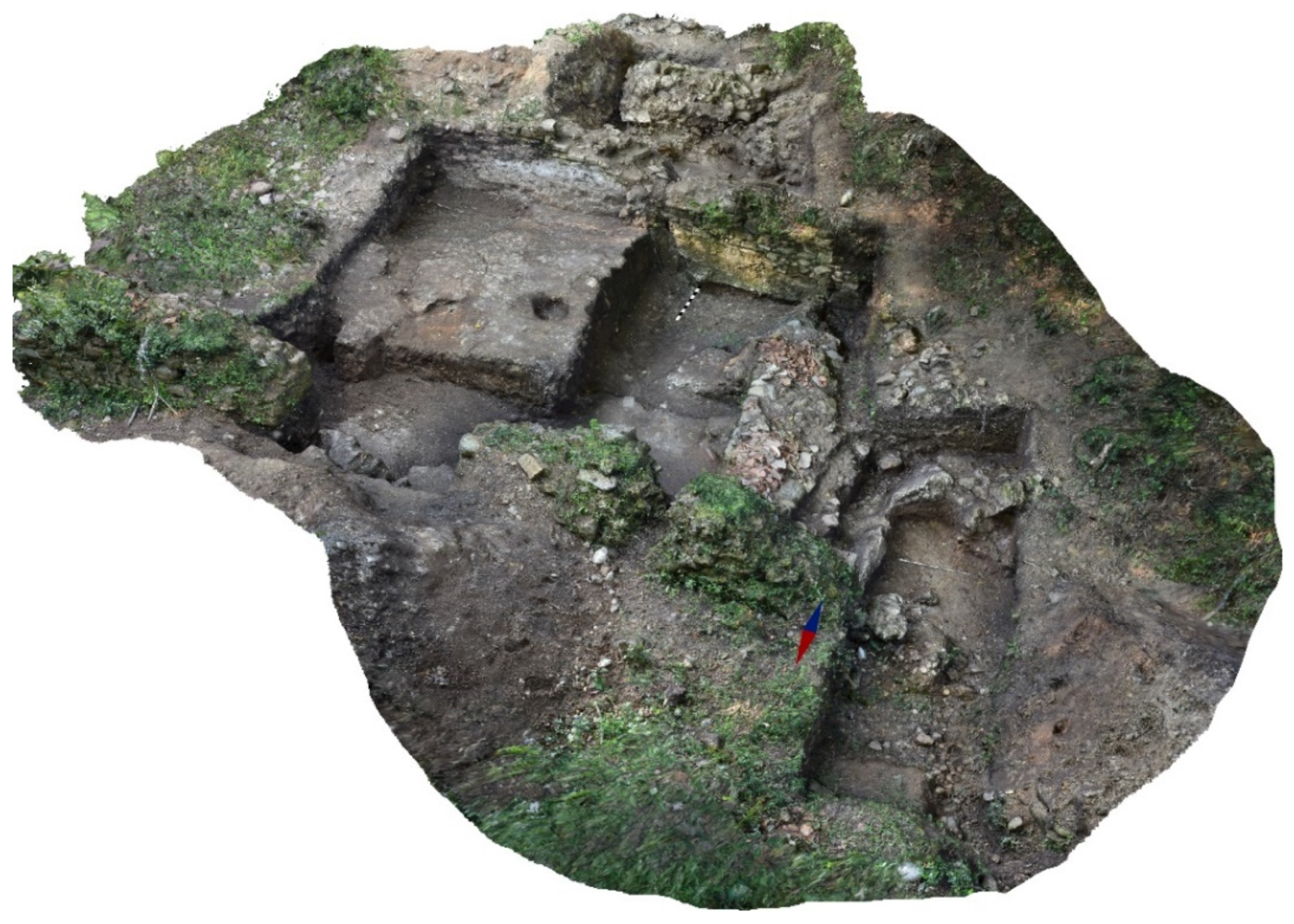
Preparation of the object. To obtain a high-quality 3D model, the key point is to preliminarily clear the vegetation. All bushes, branches, foliage, and grass should be removed from the object, as they greatly interfere with the shots at the processing stage. Tree trunks, however, practically do not affect this, since they are easily cut out of the finished model.
(3)
Shooting edges and corners. A thorough survey of the corners of the buildings is vital for high-quality stitching of the adjacent wall surfaces. It is better to capture more shots at the corners than artificially stitch the model from several parts later.
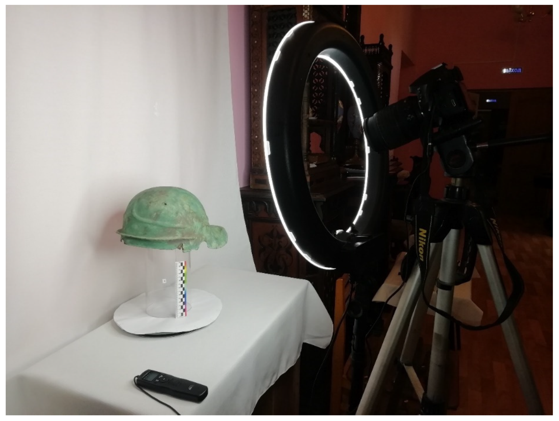
The development of photogrammetry for this group of archaeological objects can be demonstrated in the visualization of the dynamics of two excavations.
In the first case, the models of successive excavations of the “Castle” of the Markul settlement were combined, i.e., the collapsed tower was cleared of vegetation before excavations in 2019 and the successive stages of opening the area in 2020 and 2021. This made it possible to obtain a 3D picture of the sequential opening of the site and to analyze it fully in terms of geometry and stratigraphy, to obtain sections and profiles of the walls (Figure 20).
In the second case, layer-by-layer photogrammetry of the 2021 excavation site on the southwestern slope of the settlement was performed, which was rich in archaeological material. By combining 3D models of the sequential opening stages, a dynamic picture of the discovery process was obtained (Figure 21). In addition to a purely scientific result, we captured a remarkable and informative video visualization, which will later be included in the virtual exhibition of the Markul settlement museum.
A photogrammetric model of a temple or excavation site is not always the final product. After compiling dozens of architectural drawings of ancient and medieval temples in Abkhazia and Greater Sochi, it is undoubtedly true that “a high-quality architectural drawing is the result of a long, sometimes painful analysis. It contains many interpretations; the material included in the drawing undergoes a significant selection, with which one can agree or argue, but this is a product created by a specialist and for specialists in their own language. Therefore, the model, no matter how perfect it is, cannot be a substitute for formalized drawings. It can only be a tool for the architect, who can use it to solve the assigned tasks” [17]. Moreover, while photogrammetry certainly gives us more accurate results than manual measurements of objects, the resulting visualization angles are slightly different from the original sample. There are several reasons for this. For example, in arid zones where archaeological research is carried out, vegetation is practically absent; however, in the subtropical zone of the Caucasus, it is the dominant factor, and can visually distort parts of the photographed object. Furthermore, sometimes the elimination of large vegetation, e.g., trees, shrubs, and lianas, is possible through the efforts of the expedition; however, it is not possible to completely free the covered walls and fragments of the structure from ferns, mosses, and lichens. In this case, the human factor makes it possible to accurately capture the contours of architectural details and decorative elements, which is impossible for existing computer programs. For this reason, the resulting projections of architectural forms require an artist’s correction and some drawing by hand. Thus, slight differences arise in the final result, namely, the archaeologist and artist’s different visions of an object. This factor is familiar to all archeology specialists, and it often leads to protracted and time-consuming modifications. It should be noted that, in general, the skills of an artist using artistic editors significantly surpass the skills of an archaeologist. A factor complicating the final drawing of the architectural objects is that the place of residence of the expedition staff and the location of the field work often do not coincide; thus, at the end of the field season, the expedition members return to their regions, and further work is performed remotely. Graphic editors are a convenient tool for further quick adjustments. Because of the aforementioned factors, the archaeologist must adjust the existing image in an e-mail correspondence until the desired result is obtained. The adjustment stages are now described in a somewhat simplified way. In the first stage, important points of the building’s structural elements are marked (Figure 22a). After obtaining the draft drawing, which only reflects the general graphic features (Figure 22b), the adjustment is made, not according to the contrasts of the visual image, but according to the constructive significance of the architectural elements (Figure 22c). Thereafter, the final contrasts are displayed and the pointillism of small elements is performed (Figure 22d). In doing so, the process of adjusting the sketch is carried out in different applications. The archaeologist makes adjustments in any graphic editor, or even by hand with a marker and pencil, and the artist modifies the tools and filters in the Adobe Photoshop program.
Photogrammetry of artifacts: This method is applicable to small objects that can be placed (or created around them) in a basic studio. The composition of the equipment included can be the same as that proposed in [17]. For shooting, the studio included a turntable, scale bar, a tripod, a Nikon5100 reflex camera, a wired remote control for the camera, white matte fabric in the background, and a white circle on the turntable surface; the artifacts were illuminated using an LED ring lamp (Figure 23). Such a studio greatly simplifies and speeds up the shooting process, since the sharpness of the lens does not change during the series of shots, the artifact is rotated at the same angle, the camera is fixed rigidly, the frames are not blurred, and the white background is easily and quickly removed using masks during the primary processing of photographs. Moreover, the even soft light does not cause glare or shadows, producing a high-quality texture. The necessary direction of the light and the position of the shadows are set during the final rendering by specifying the position of the virtual light source, which allows the shape of the object to be emphasized in the right place.
In the field, it is sometimes impossible to assemble a studio, so the shooting process should be simplified by limiting the equipment to daylight diffused light, a stand, a scale bar, and white drapery. Shooting under these conditions is carried out by walking around a stationary artifact. With soft diffused illumination the results are not affected [18].
By setting the camera statically and turning the turntable with the artifact at a certain angle, a circuit made up of 16–24 shots is created. Furthermore, the camera installation angle changes in height by 15–20° and the procedure is repeated. Thus, several survey cones are obtained, which allows one to create a 3D model of the artifact (Figure 24). The scale bar presented in the model allows the item to be scaled to natural size, afterwards it is removed.
This technique was initially conceived when creating samples for the virtual exhibition of the museum of the history of the resort city of Sochi [19]. It was then applied to the artifacts that were found during the excavations of the Markul settlement.
In 2020, a bowl was found, and 2021 yielded a large number of finds, including pithos and five vessels from the burial. Their preservation is of both scientific and public interest. The construction of 3D models of small objects, carried out according to proven algorithms, produced suitable results. The necessary measurements were made for them, and projections and sections were built (Figure 25).
When performing photogrammetry on large and heavy pithoses, we encountered certain technical challenges. The weight and size of these items did not allow us to create a photo studio in the field that fully functioned with the shooting technology. Pithos were filmed in the open air on the grass, first in the usual position, and then upside down. As a result, the reflection of light from the grass produced color on the bottom surface of the pithos, and the light from the sky produced shadows. This hindered the automatic recognition and stitching of the two series, i.e., bottom and top. Therefore, to obtain a complete 3D model, the two halves had to be stitched by hand in 3DsMax. In this regard, the finished model exhibits slight differences in the texture of the upper and lower half of the pithos (Figure 26).
We were unable to reshoot the pithos due to it being the end of the season, but technical measures and shooting conditions were outlined in order to avoid such faults:
the use of a white fabric when shooting excludes any color from light reflections;
separation of the object from the surface of the earth excludes dense shadows (with the use of a pedestal, stand);
the use of diffused artificial lighting in the form of a ring lamp excludes oblique shadows or the soft diffused light of an overcast sky;
using a turntable was beneficial.
All the above actions, in some way, can be reduced to organizing a photo studio on site in the field for object shooting. Labor costs for its construction will be covered by the time of subsequent processing of the material.

4. Conclusions

In the course of the Markul expedition, the following main applications of photogrammetry were performed:
(1)
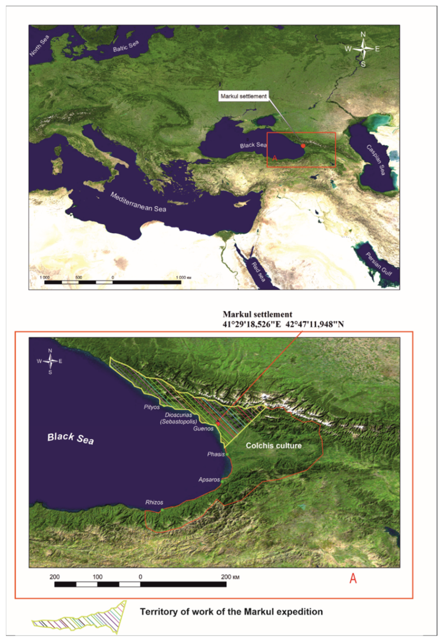
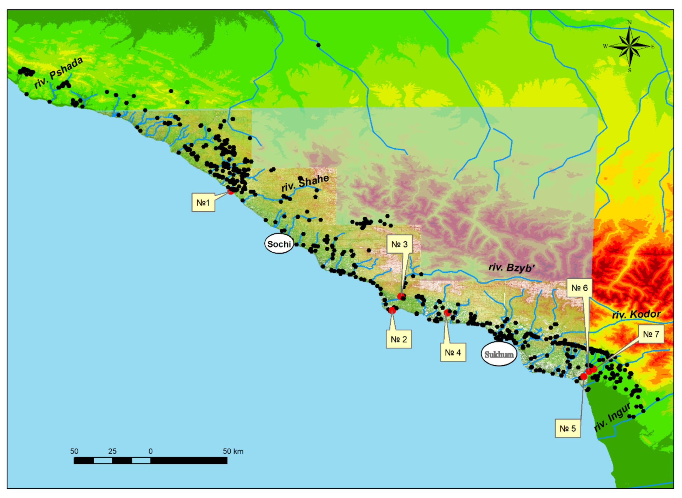
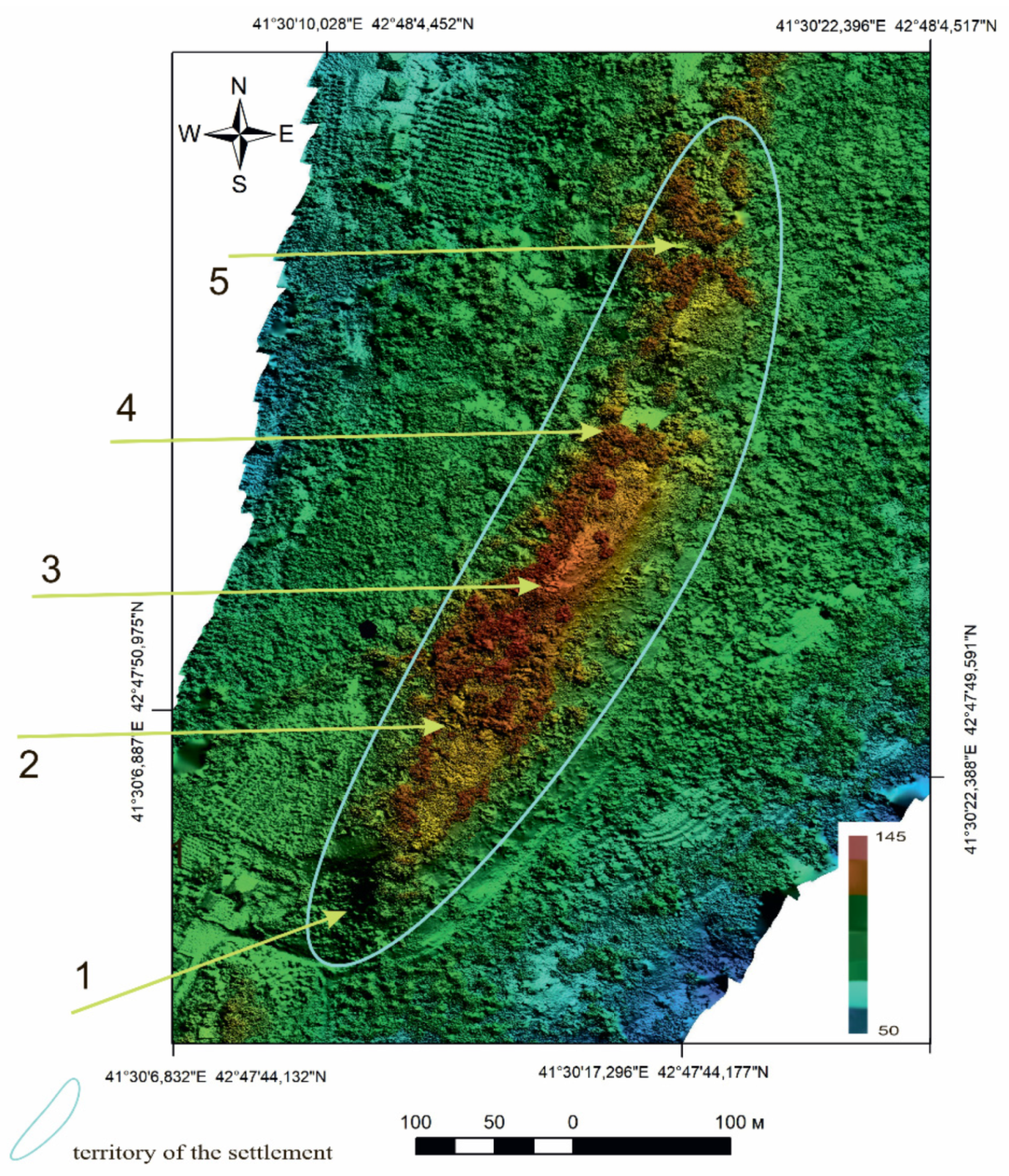
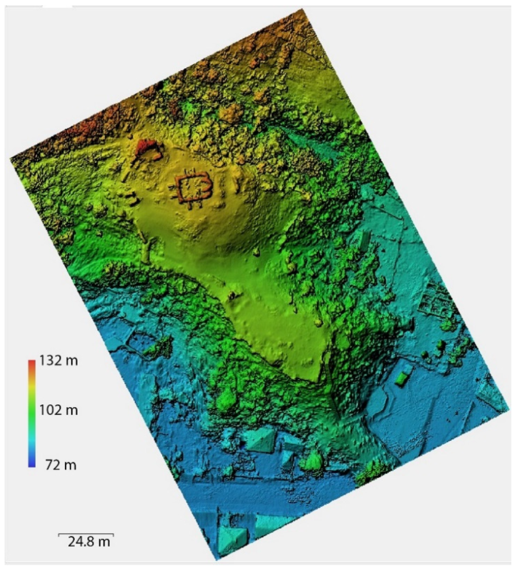
Physiography and aerial photography of the study areas.
(2)
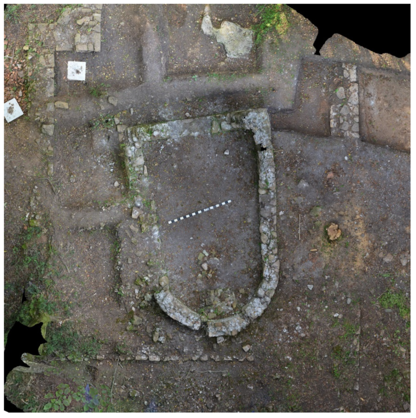
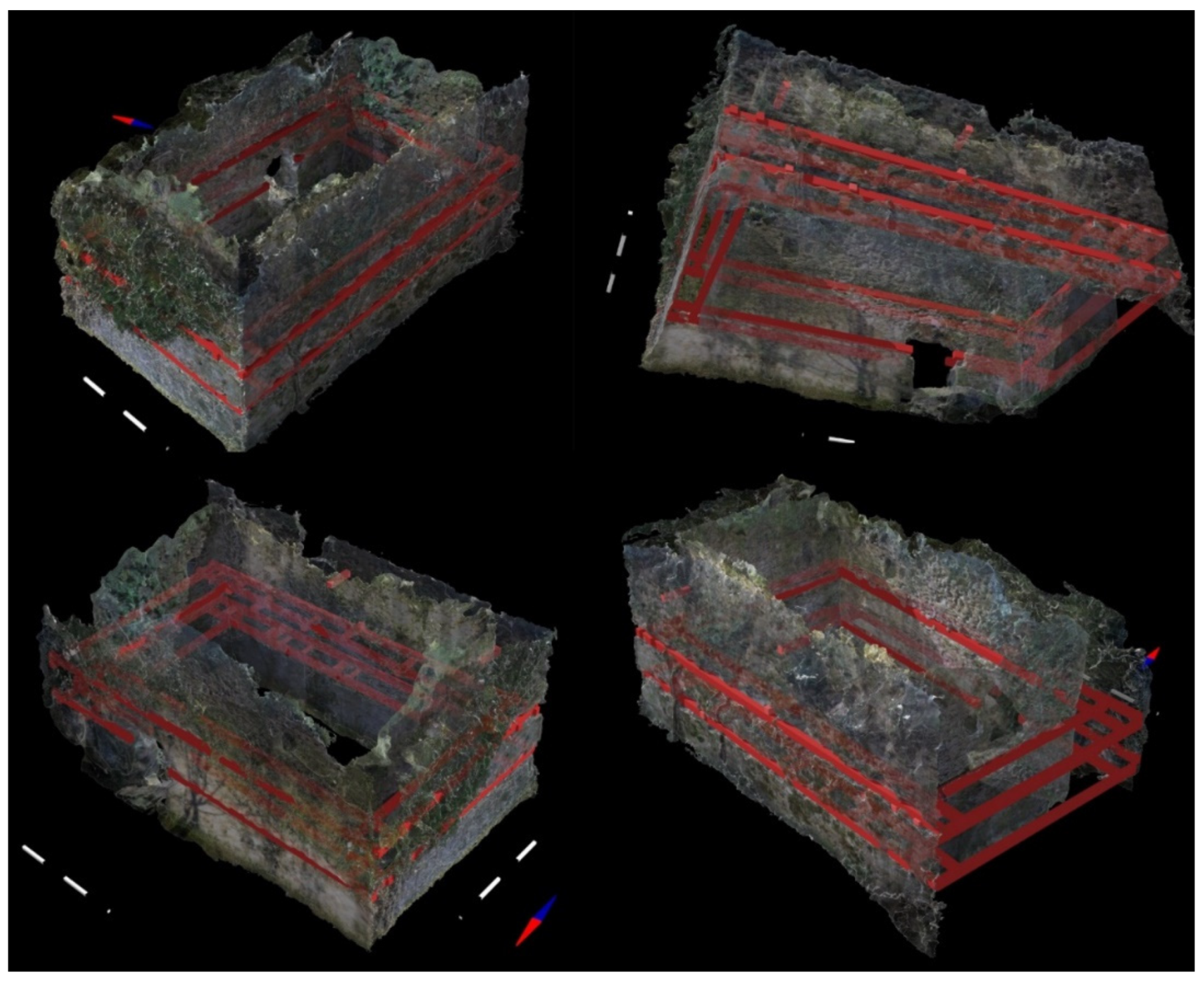
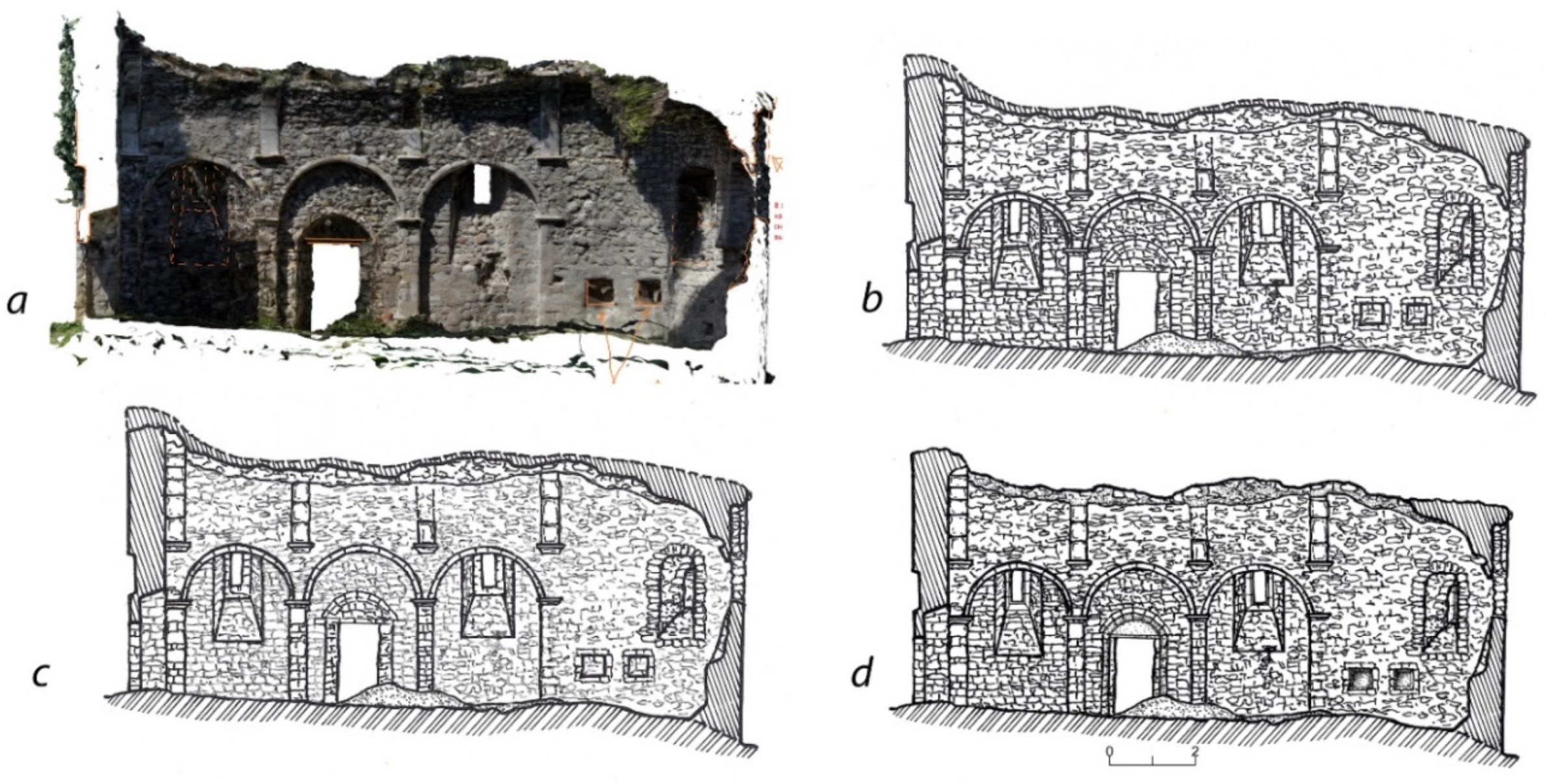
Fixing the current state of the sites and architectural features; obtaining plans, projections, and sections.
(3)
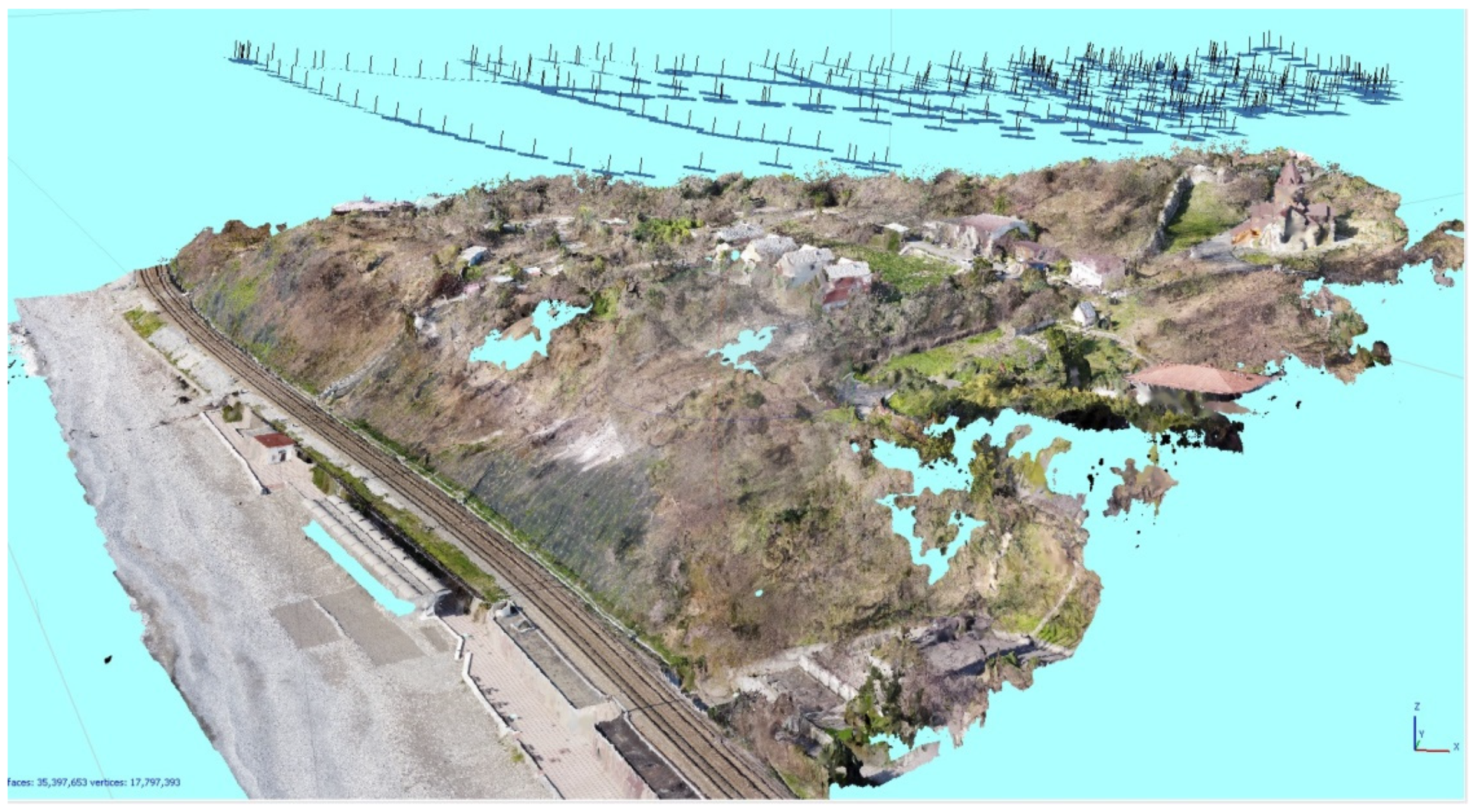
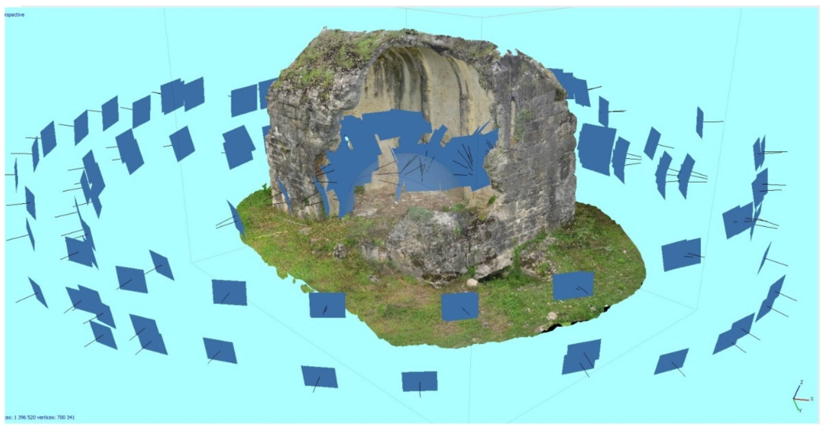
Obtaining 3D models of sites; video visualization.
(4)
Documenting excavations; obtaining plans, sections, excavation profiles.
(5)
The fixation of finds.
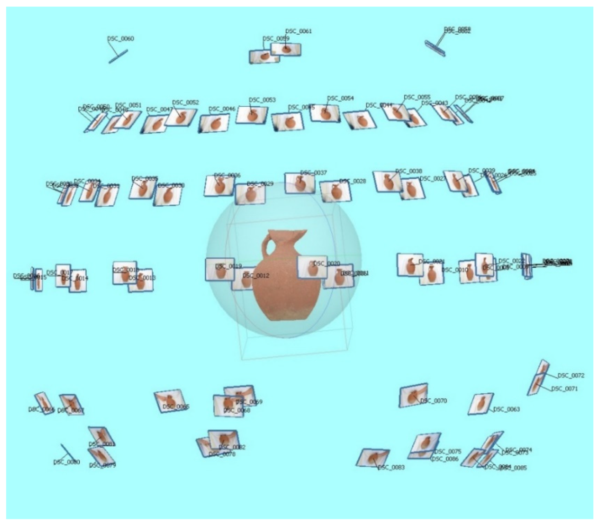
(6)
Obtaining 3D models of artifacts; accumulating a databank of finds to create a virtual exhibition for the Markul settlement museum.
(7)
Camera processing of the material filmed during the season, which allowed us to analyze objects and artifacts, measurements, drawings, and sections remotely as all archaeological material remained in the Republic of Abkhazia; remote work with 3D images of excavations in the off-season also allowed us to plan the research for the next season.
(8)
The exchange of data with experts, which allowed us to provide a 3D model of an object or artifact to specialists via the Internet, displaying it from different sides, which made it easier to obtain an expert opinion.
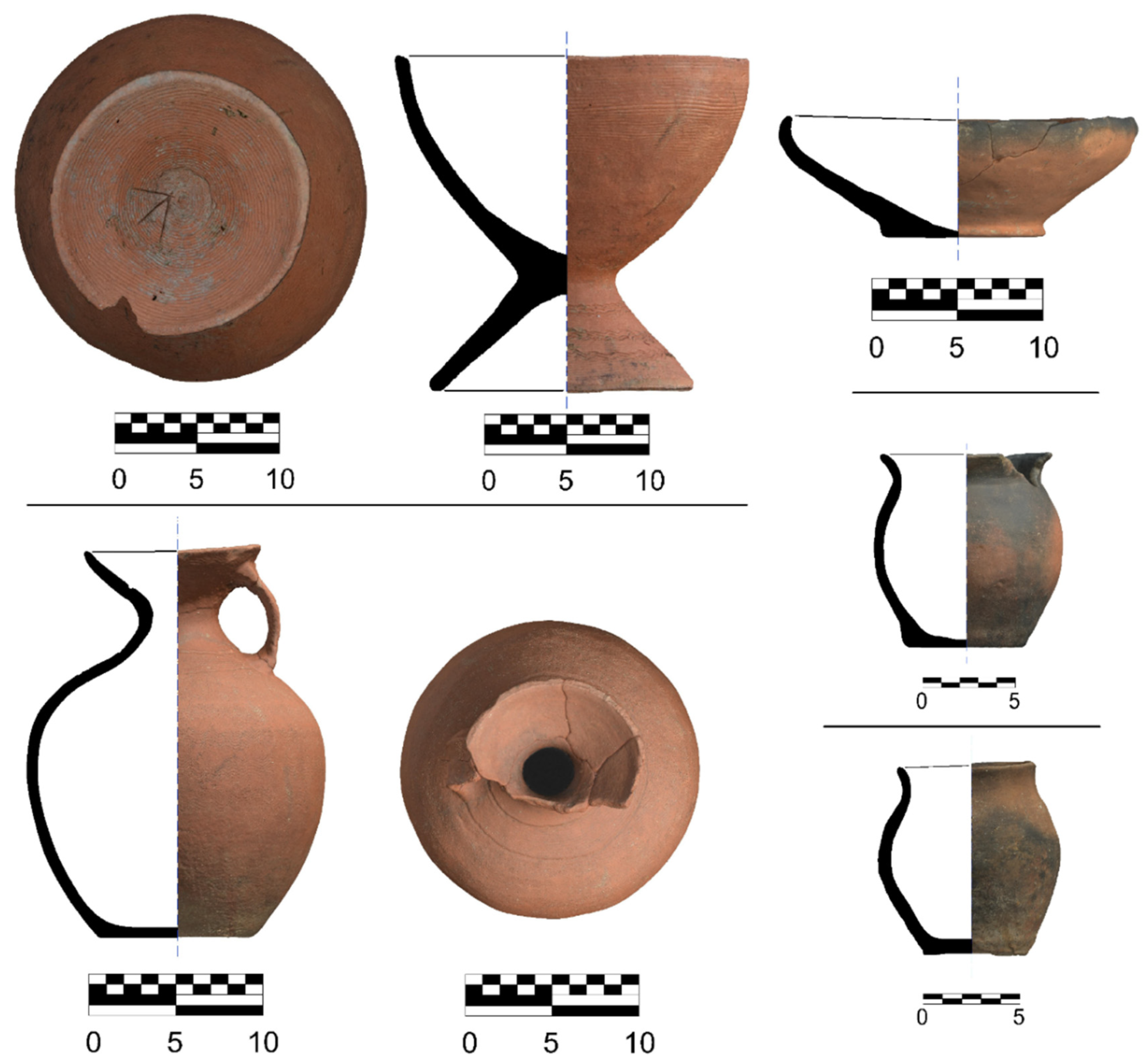
(9)
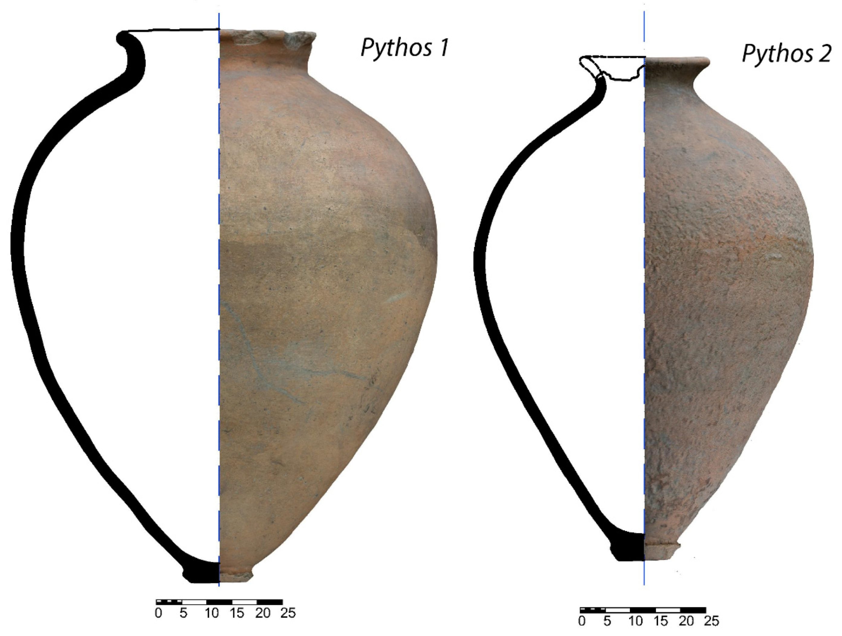
The restoration of the original form of partially fragmented artifacts; the virtual reconstruction of archaeological sites.
With further application of photogrammetry, the range of its tasks will undoubtedly expand. The use of UAVs for reconnaissance of the territory is a field with huge potential, including with the use of narrow-spectrum imagery.
As regards methodological developments, after analyzing the use photogrammetry in the Markul archaeological expedition, it should be noted that the methods developed for the groups of archaeological objects described above are generally recommended. Each site requires its own individual approach, determined by its size, geometry, shooting conditions, and other parameters. Moreover, no matter how convenient and promising digital technologies are, the most important role is still played by the researcher, and in the end, interpretation and refinement of the results of digital technologies is always required.
By sketching a photograph of the resulting foreshortening of the object on tracing paper, the artist often conveys the image of the visible object that is true from the view of artist in terms of brightness; however, this may not accentuate important and significant details with contrast. This is due to the fact that illumination of the object in the field is determined by the weather, and many real elements that differ from each other appear to be of the same contrast. Another factor is that, for various reasons, the artist is often not present for entire the expedition. Moreover, in a mountainous wooded area, and often in bad weather conditions, drawing on paper is impossible. In addition, people of different professions have different ways of thinking, which is a significant psychological factor.
Visual–figurative thinking is reflection of reality. When analyzing the nature of the origin of figurative thinking, it was revealed that practical activity and communication are the universal basis on which the ability to construct culturally given images is formed [20]. It should be noted that all thinking processes take place using more or less generalized, abstract concepts, and more or less sensory images are included in this; however, the concept and the image are presented in an indissoluble unity.
Verbal–logical thinking differs from other types of thinking in that it operates not with ideas, but with concepts. Genetically, the early forms of concept are closely related to the figurative structure of thinking and arise as a result of generalization and abstraction of the clearly presented properties of objects [20]. In simpler terms, different people perceive an object in different ways. Some see it in an image, while others perceive it as a set of precise concepts, e.g., size, texture, color, etc. As a result, different images appear in the minds of researchers when they see the same image.
In the context of the aforementioned circumstances, it is rather difficult to fix the remnants of images on elements of architecture. These images not only have been partially lost, but are often located in spatial orientation, i.e., we see the remains of a fragment of an unknown object oriented in an unknown way. Therefore, for example, a drawing of the image of a lion from the Jal Akuaskia temple (Figure 2 No. 7 and Figure 27) [21], which at the initial stage was inverted and partially damaged, was processed in Adobe Photoshop light filters.
The resulting clearer contours of the image allowed us to determine that the image was one of a lion, although the initially inverted paws resembled swaying ears of feather grass (Figure 28).
In conclusion, let us give some possibilities for further work. The expedition clearly faces the task of making 3D photogrammetric models of all artifacts found on the site and creating a complete virtual museum of the Markul site. Thus far, individual 3D models are available for general access on the expedition Facebook page (https://www.facebook.com/markul.expedition, accessed on 12 February 2022).
Moreover, providing open access directly to the GIS, in which data obtained using photogrammetry are integrated in the form of separate layers and hyperlinks, has not yet been fully accomplished. This is an objective for the near future. The main challenge in this respect is the coordination of the geographical data in order to combine, on the one hand, the possibility of the general public accessing the cultural heritage, and, on the other, protecting cultural heritage objects from looting.

Author Contributions

G.T.—management of archaeological exploration, working in GIS, and preparation of a publication; K.G.—processing of 3D models in programs and preparation of a publication A.K. (Andrey Kizilov)—preparation of drawings; A.K. (Anastasya Kizilova)—painter; V.Y.—photogrammetric shooting in the field and processing of 3D models in programs; G.Y.—participation in excavations and exploration, technical support of work and adjustment of equipment in the field and preparation of a publication. All authors have read and agreed to the published version of the manuscript.

Funding

The work was carried out within the framework of NIOKTR 122011200269-4. “The Black Sea and Central Asian periphery of the ancient world and the nomadic communities of Eurasia: at the crossroads of cultures and civilizations”.

Institutional Review Board Statement

Not applicable.

Informed Consent Statement

Not applicable.

Data Availability Statement

The data on the basis of which the study was conducted are presented in the references provided to the article.

Conflicts of Interest

The authors declare no conflict of interest.

References

  1. Chrysanthi, A.; Katifori, A.; Vayanou, M.; Antoniou, A. Place-Based Digital Storytelling. The Interplay between Narrative Forms and the Cultural Heritage Space. In Emerging Technologies and the Digital Transformation of Museums and Heritage Sites. RISE IMET 2021. Communications in Computer and Information Science; Shehade, M., Stylianou-Lambert, T., Eds.; Springer: Berlin, Germany, 2021; Volume 1432, pp. 127–138. [Google Scholar] [CrossRef]
  2. Bruno, N. Photogrammetric Techniques for Promotion of Archaeological Heritage: The Archaeological Museum of Parma (ITALY). Int. Arch. Photogramm. Remote Sens. Spat. Inf. Sci. 2016, XLI, 243–250. Available online: https://www.academia.edu/40177957/PHOTOGRAMMETRIC_TECHNIQUES_FOR_PROMOTION_OF_ARCHAEOLOGICAL_HERITAGE_THE_ARCHAEOLOGICAL_MUSEUM_OF_PARMA_ITALY (accessed on 25 December 2021). [CrossRef]
  3. Wallace, C.A.B. Photogrammetry in Mediterranean Archaeology. Master’s Thesis, University of Waterloo, Waterloo, ON, Canada, 29 March 2016. Available online: https://uwspace.uwaterloo.ca/handle/10012/10344 (accessed on 25 December 2021).
  4. Patias, P.; Olga, G.; Charalampos, G.; Anastasios, S.; Maria, T. Photogrammetric Documentation and Digital Representation of Excavations at Keros Island in the Cyclades. In Proceedings of the 22nd CIPA Symposium Great Learning & Digital Emotion, Kyoto, Japan, 11–15 October 2009; Available online: https://www.cipaheritagedocumentation.org/wp-content/uploads/2018/12/Patias-e.a.-Photogrammetric-Documentation-and-Digital-Representation-of-Excavations-at-Keros-Island-in-the-Cyclades.pdf (accessed on 25 December 2021).
  5. Stamnas, A.; Kaimaris, D.; Georgiadis, C.; Patias, P. Comparing 3D digital Technologies for Archaeological Fieldwork Documentation. The Case of Thessaloniki Toumba Excavation, Greece. In Proceedings of the 28th CIPA Symposium Great Learning & Digital Emotion, Beijing, China, 28 August–1 September 2021; Volume XLVI-M-1-2021, pp. 713–720. Available online: https://www.researchgate.net/publication/354206543_COMPARING_3D_DIGITAL_TECHNOLOGIES_FOR_ARCHAEOLOGICAL_FIELDWORK_DOCUMENTATION_THE_CASE_OF_THESSALONIKI_TOUMBA_EXCAVATION_GREECE/fulltext/612c382938818c2eaf6c530e/COMPARING-3D-DIGITAL-TECHNOLOGIES-FOR-ARCHAEOLOGICAL-FIELDWORK-DOCUMENTATION-THE-CASE-OF-THESSALONIKI-TOUMBA-EXCAVATION-GREECE.pdf (accessed on 25 December 2021). [CrossRef]
  6. Porter, S.T.; Roussel, R.; Soressi, M. A Simple Photogrammetry Rig for the Reliable Creation of 3D Artifact Models in the Field. Lithic Examples from the Early Upper Paleolithic Sequence of Les Cottés (France). Adv. Archaeol. Pract. 2016, 4, 71–86. [Google Scholar] [CrossRef]
  7. Zakrzewski, P. Geodesy and Photogrammetry in Archaeology. Advanced documentation methods used by the Kuwaiti-Polish Archaeological Expedition 2019. In Stories Told around the Fountain. Papers Offered to Piotr Bieliński on His 70th Birthday; Pieńkowska, A., Szeląg, D., Zych, I., Eds.; University of Warsaw Press: Warsaw, Poland, 2019; pp. 759–776. Available online: https://www.academia.edu/41267074/Geodesy_and_photogrammetry_in_archaeology_Advanced_documentation_methods_used_by_the_Kuwaiti_Polish_Archaeological_Expedition?email_work_card=view-paper (accessed on 25 December 2021).
  8. Trebeleva, G.V. Markul Settlement in Eastern Abkhazia. In New Archaeological Projects: Reconstructing the Past; Makarov, N.A., Ed.; Institute of Archaeology: Moscow, Russia, 2019; pp. 144–147. [Google Scholar]
  9. Demers, M.N. Fundamentals of Geographic Information Systems, 3rd ed.; Wiley India Pvt. Limited: New Delhi, India, 2008; p. 484. [Google Scholar]
  10. Trebeleva, G.V.; Glazov, K.A.; Kizilov, A.S.; Sakania, S.M. Application of 3D-Photogrammetry of Archaeological Objects in Mountainous and Wooded Areas of the Western Caucasus. In Proceedings of the VI (XXII) All-Russian Archaeological Congress in Samara, Samara, Russia, 12–14 September 2020; Volume 3, pp. 178–180. Available online: https://elibrary.ru/download/elibrary_46281139_86597726.pdf (accessed on 14 February 2022).
  11. Trebeleva, G.V.; Sakania, S.M.; Glazov, K.A.; Kizilov, A.S.; Yurkov, G.Y. Late Antique and Medieval Temples of Abkhazia: GIS, Research Using Photogrammetry and Creation of 3D Models. Archaeol. Geoinform. 2021, 10. Available online: https://www.archaeolog.ru/media/periodicals/agis/AGIS-10/Trebeleva/page1.html (accessed on 25 December 2021). [CrossRef]
  12. Trebeleva, G.; Kizilov, A.; Glazov, K.; Yurkov, V.; Yurkov, G. Photogrammetry in the Study of the Antique and Medieval Archaeological Site of Markul (Village Markula, Ochamchira Region, Republic of Abkhazia) in Northwestern Colchis Area (Black Sea Coast of the Caucasus). Geosciences 2020, 10, 489. [Google Scholar] [CrossRef]
  13. Luis-Ruiz, J.M.D.; Sedano-Cibrián, J.; Pereda-García, R.; Pérez-Álvarez, R.; Malagón-Picón, B. Optimization of Photogrammetric Flights with UAVs for the Metric Virtualization of Archaeological Sites. Application to Juliobriga (Cantabria, Spain). Appl. Sci. 2021, 11, 1204. [Google Scholar] [CrossRef]
  14. Trebeleva, G.; Glazov, K.; Kizilov, A.; Sakania, S.; Yurkov, V.; Yurkov, G. Roman Fortress Pitiunt: 3D-Reconstruction of the Site Based on the Materials of Archaeological Research and Geological Paleoreconstructions. Appl. Sci. 2021, 11, 4814. [Google Scholar] [CrossRef]
  15. Trebeleva, G.V.; Kizilov, A.S.; Glazov, K.A.; Khondziya, Z.G.; Yurkov, G.Y. Defensive Constructions of the Markula Hillfort: The Dating Revisited. Brief Commun. Inst. Archaeol. 2019, 256, 230–242. Available online: https://www.archaeolog.ru/media/ksia/ksia-256-redu.pdf#page=230 (accessed on 14 February 2022). [CrossRef]
  16. Sakania, S.M.; Trebeleva, G.V. Late Antique and Medieval Christian Churches of the North-Eastern Black Sea Region. Catalog. Volume 1. Western Abkhazia (Gagra, Gudauta, Sukhum Regions); Magnitogorsk Printing House: Magnitogorsk, Russia, 2019; p. 201. [Google Scholar]
  17. Lebedev, M.A. The Use of Photogrammetry in the Excavation of Ancient Egyptian Rock Tomb Complexes: Prospects and Limitations of the Method. Archaeol. Geoinform. 2021, 10. Available online: https://www.archaeolog.ru/media/periodicals/agis/AGIS-10/Lebedev/page1.html (accessed on 25 December 2021). [CrossRef]
  18. Grushin, S.; Sosnovskyi, I. Photogrammetry in Archeology-Methods and Perspectives. Theory Pract. Archaeol. Res. 2018, 1, 99–105. [Google Scholar] [CrossRef]
  19. Galishcheva, E.V.; Glazov, K.A. Archaeological Heritage in the Format of Digital Technologies of the Exposition and Exhibition Space of the Museum of the History of the Resort City of Sochi. In Proceedings of the Museum: Past, Present and Future: Materials of the Interregional Scientific and Practical Conference (Felitsyn Readings-XXI), Krasnodar, Russia, 11–15 October 2019; pp. 59–62. [Google Scholar]
  20. Kizilov, A.S. Individualization of Teaching Landscape Design for University Students, Taking into account their Dominant Types of Thinking. Ph.D. Thesis, Scientific and Educational Center of the Russian Academy of Education, Sochi, Russia, 27 December 2004. (In Russian). [Google Scholar]
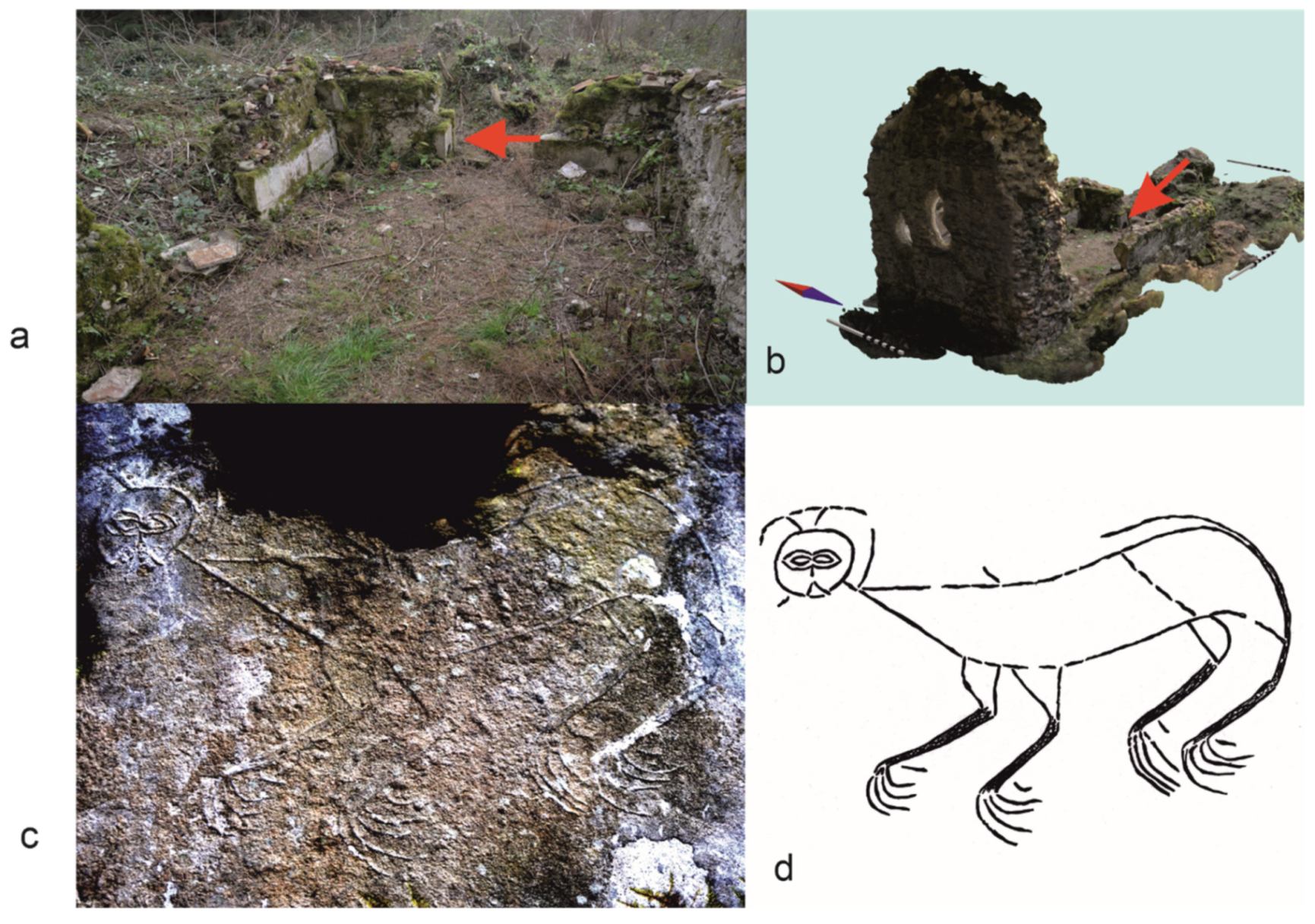
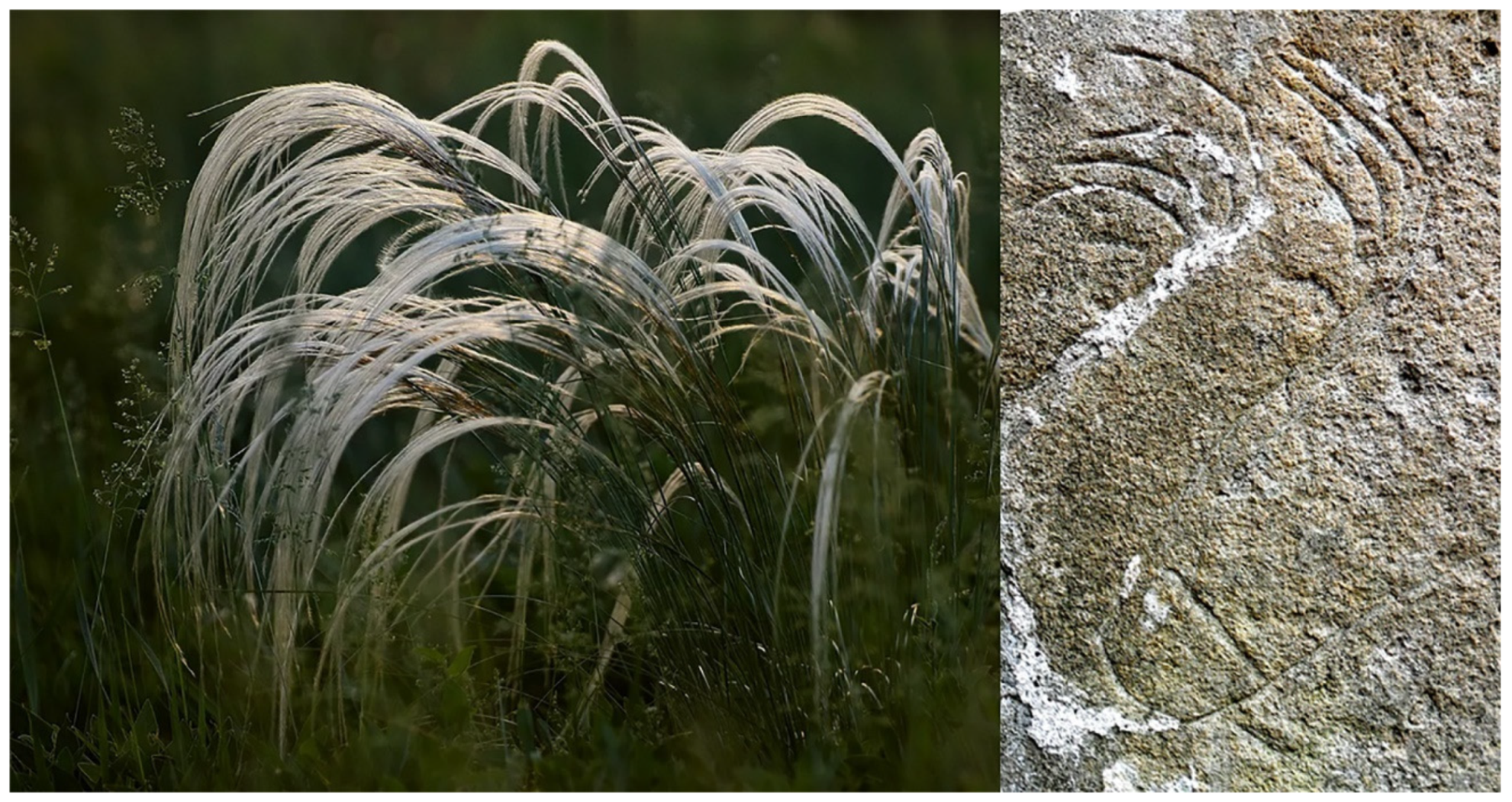
  21. Trebeleva, G.V.; Sakania, S.M.; Lobkovskii, V.A.; Kizilov, A.S. Stone Art Feline Images of Medieval Abkhazia (based on recent artifacts found during Markul expedition). Strat. Plus 2021, 5, 147–156. [Google Scholar] [CrossRef]
Figure 1. Location of Northwestern Colchis: the territory of the Markul expedition and the location of the Markul settlement.
Applsci 12 02052 g001
Figure 2. Overall map of archaeological sites, visualized from GIS (the sites named in the text are indicated by numbers).
Applsci 12 02052 g002
Figure 3. Implementation of layering and hyperlinks in GIS: (a) orthophotomaps of the Markul settlement (Figure 2, No. 6); (b) orthophotomaps of the protective tower excavation, with the excavation site integrated as a separate layer in the GIS; (c) GIS hyperlink in the photograph of artifacts found at the castle excavation site; (d) Alakhash tower outlines in the orthomosaic and hyperlink in the photo, 3D model, and reconstruction of the tower.
Applsci 12 02052 g003
Figure 4. Digital elevation model (DEM) of the Markul settlement. 1—excavations on the southwestern slope; 2—south Alakhash-Abaa tower; 3—temple; 4—a fragment of the wall; 5—northern tower.
Applsci 12 02052 g004
Figure 5. The position of the cameras when shooting the Godlik fortress from the UAV.
Applsci 12 02052 g005
Figure 6. Orthophotoplan of the territory of Godlik fortress.
Applsci 12 02052 g006
Figure 7. Digital elevation model (DEM) of Godlik fortress.
Applsci 12 02052 g007
Figure 8. Position and tilt of cameras when photographing Pitiunt fortress, with a shooting height of 25 m.
Applsci 12 02052 g008
Figure 9. Introducing a series of images from a height of 250 m to the estimation.
Applsci 12 02052 g009
Figure 10. Orthophotoplan of the territory of Pitiunt fortress.
Applsci 12 02052 g010
Figure 11. DEM of Pitiunt fortress.
Applsci 12 02052 g011
Figure 12. Trajectory of shooting and tilt of the camera during photogrammetry of Bzyb fortress.
Applsci 12 02052 g012
Figure 13. Orthophotoplan of Bzyb fortress.
Applsci 12 02052 g013
Figure 14. DEM of Bzyb fortress.
Applsci 12 02052 g014
Figure 15. Plan of the excavation of the Markul temple.
Applsci 12 02052 g015
Figure 16. Illustration of the use of beams in the construction of the Alahash-Abaa tower: view of the 3D model from different angles.
Applsci 12 02052 g016
Figure 17. An example of camera movement during the photogrammetry of the Kulanurhua temple (Figure 2, No. 4).
Applsci 12 02052 g017
Figure 18. Illustration of the flight trajectory around the Bzyb temple.
Applsci 12 02052 g018
Figure 19. Orthophotoplan of the Bzyb temple.
Applsci 12 02052 g019
Figure 20. The combined model of the castle excavation site for the 2019–2021 season.
Applsci 12 02052 g020
Figure 21. A 3D model of one of the intermediary excavations in 2021 on the southwestern slope of the Markul settlement.
Applsci 12 02052 g021
Figure 22. Drawing of the northern wall of the temple Markul-2 (Figure 2, No. 5): structural elements of the building are marked on the photogrammetric model (a); a draft drawing that only reflects general graphical features (b); a draft drawing that displays the constructive meaning of architectural elements (c); final drawing with final contracts displayed and a dot image of small elements (d).
Applsci 12 02052 g022
Figure 23. Photo studio for object shooting: turntable, SLR camera, tripod, camera control panel, white fabric in the background, and circular illumination lamp.
Applsci 12 02052 g023
Figure 24. Illustration of the shooting algorithm on one of the artifacts from the territory of the Markul settlement.
Applsci 12 02052 g024
Figure 25. Examples of artifact photogrammetry.
Applsci 12 02052 g025
Figure 26. Results of photogrammetry of pithos.
Applsci 12 02052 g026
Figure 27. Image of a lion from Jal Akuaskia temple: location of the image in the photo of the temple (view from the east) (a); location of the image on the photogrammetric model of the temple (view from the northeast) (b); an image inverted and processed in Adobe Photoshop light filters (c); drawing of an image (d).
Applsci 12 02052 g027
Figure 28. Feather grass ears and the paws from the image of a lion from Jal Akuaskia temple.
Applsci 12 02052 g028
Publisher’s Note: MDPI stays neutral with regard to jurisdictional claims in published maps and institutional affiliations.

