
Use of Different Digitization Methods for the Analysis of Cut Marks on the Oldest Bone Found in Brittany (France)

 , , , , and
Abstract
1. Introduction
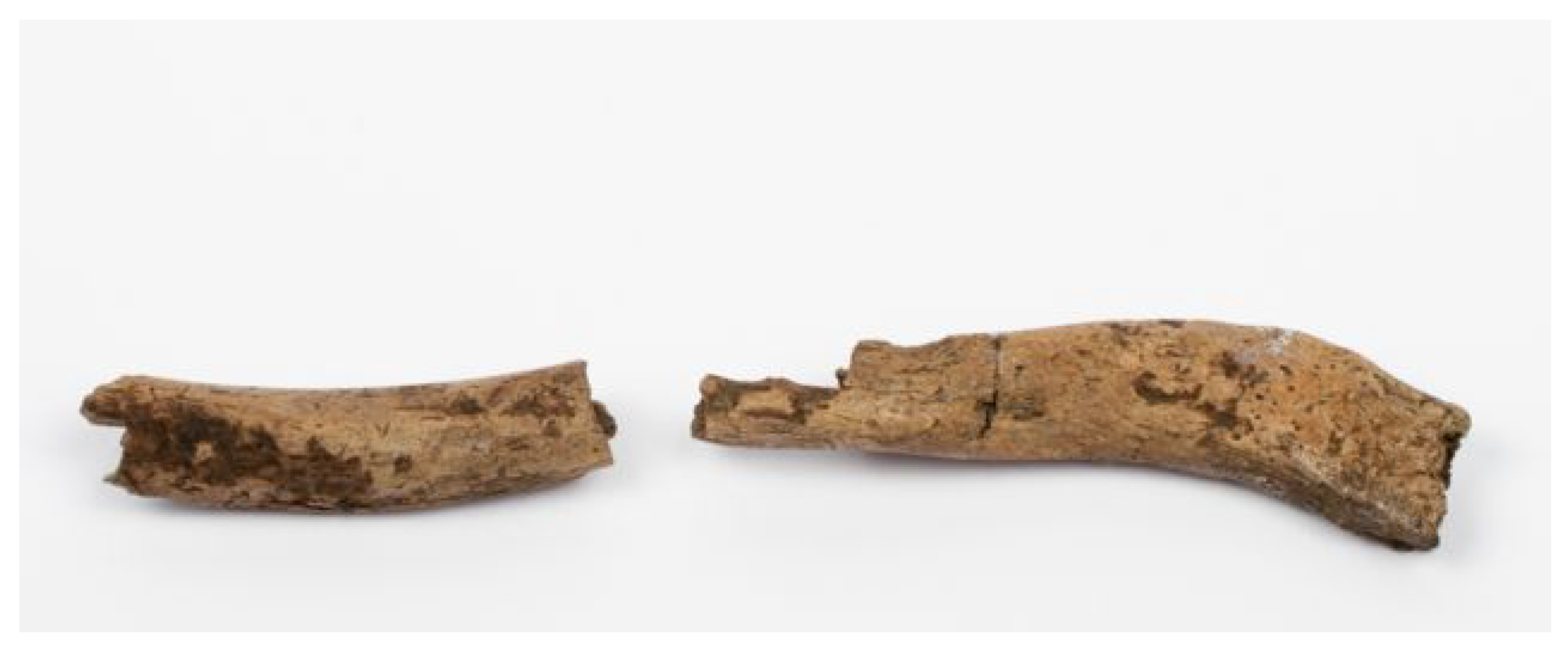
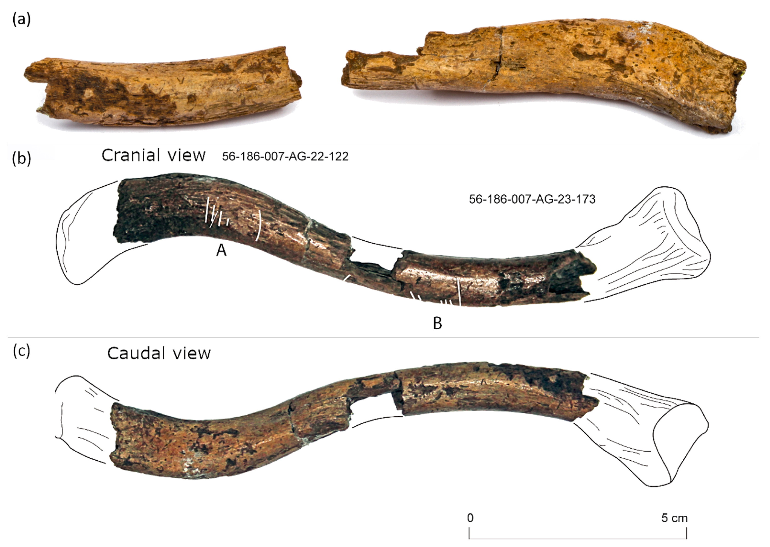
2. Materials
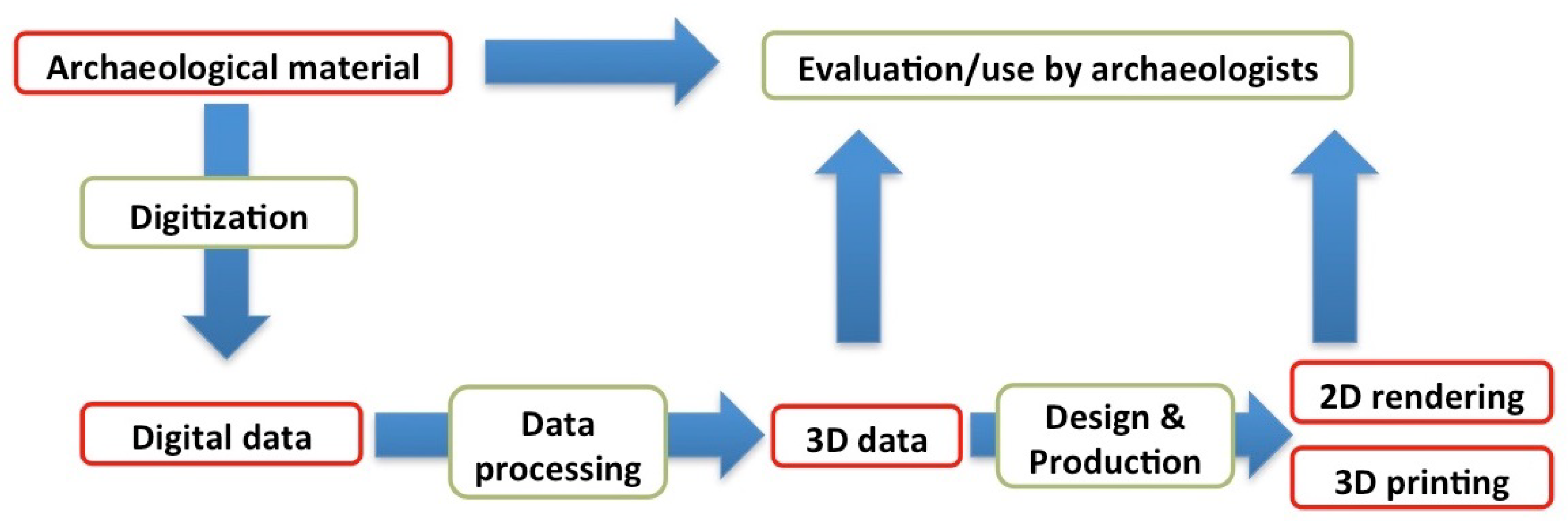
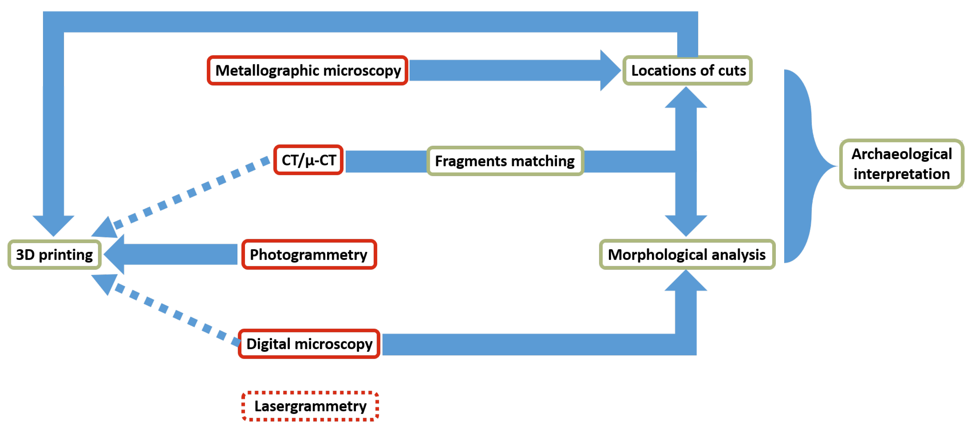
3. Methods
3.1. Metallographic Microscopy
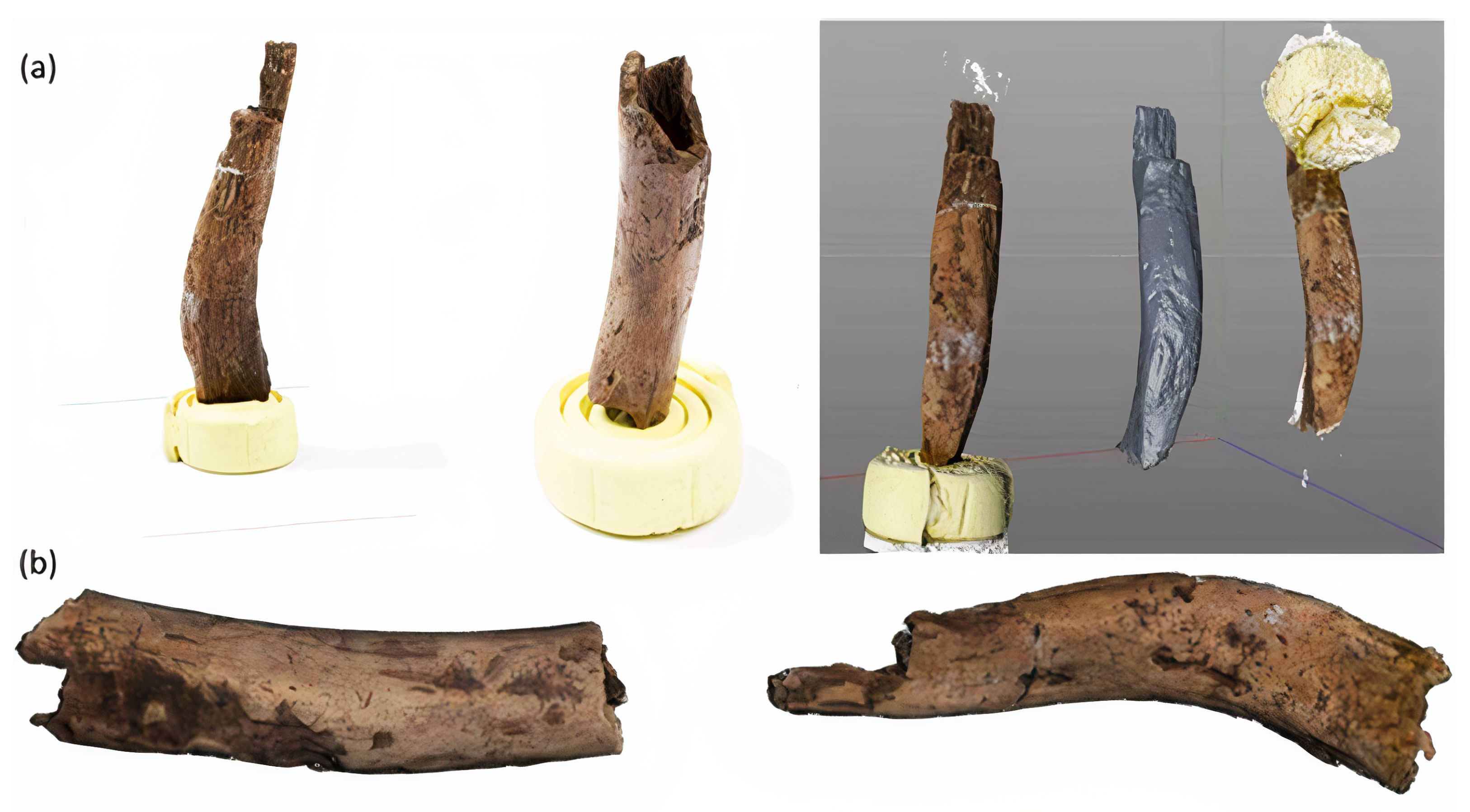
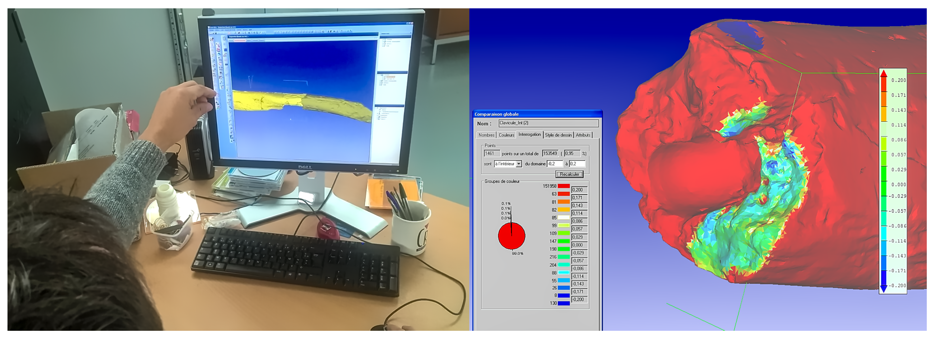
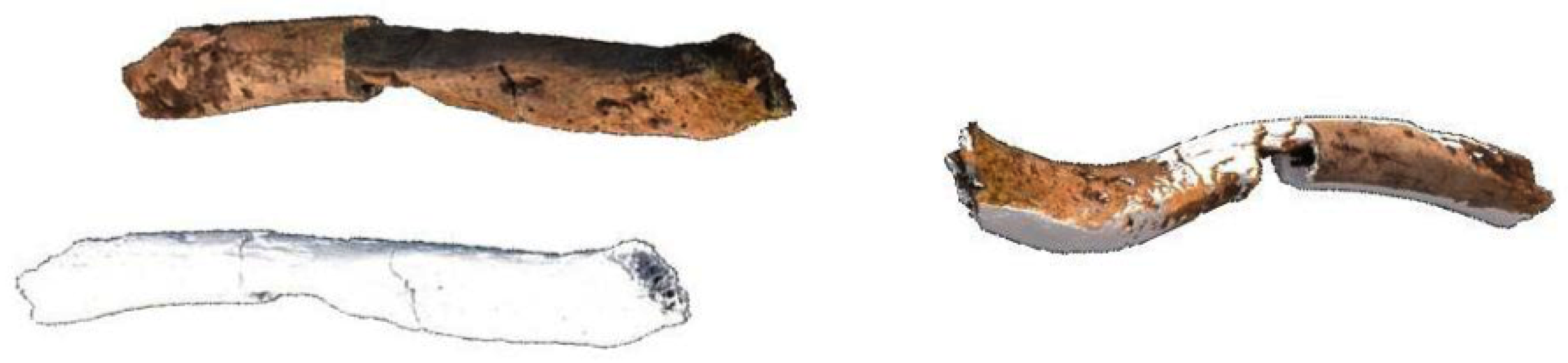
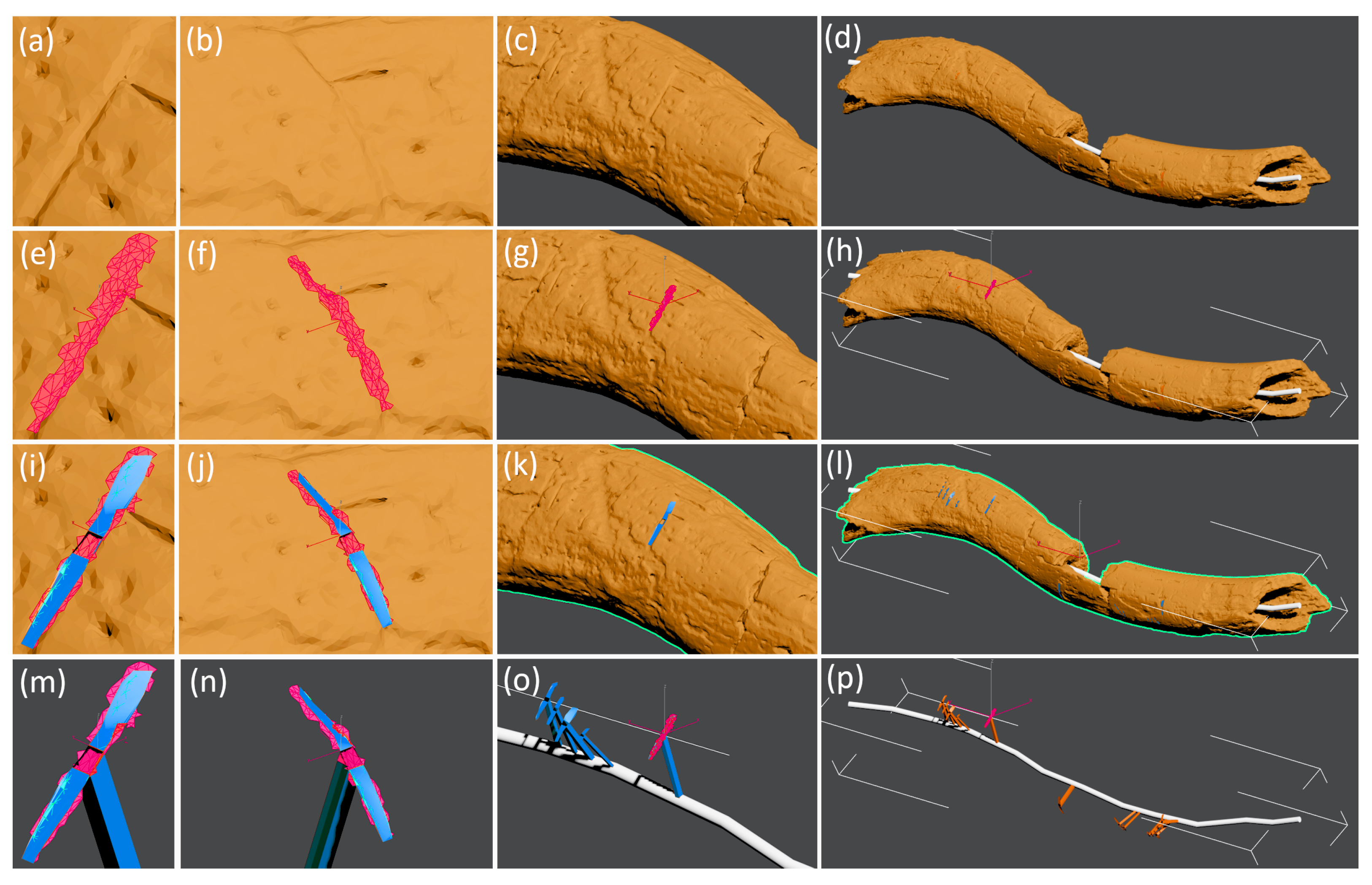
3.2. Photogrammetry
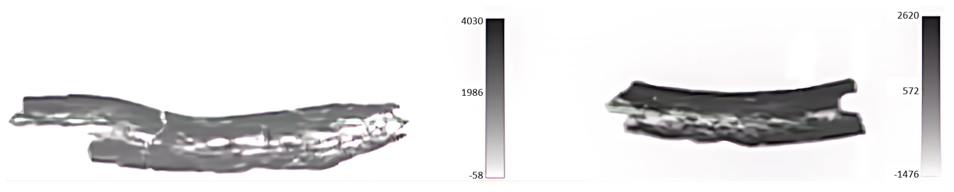
3.3. CT and µ-CT
3.4. Digital Microscopy
4. Results
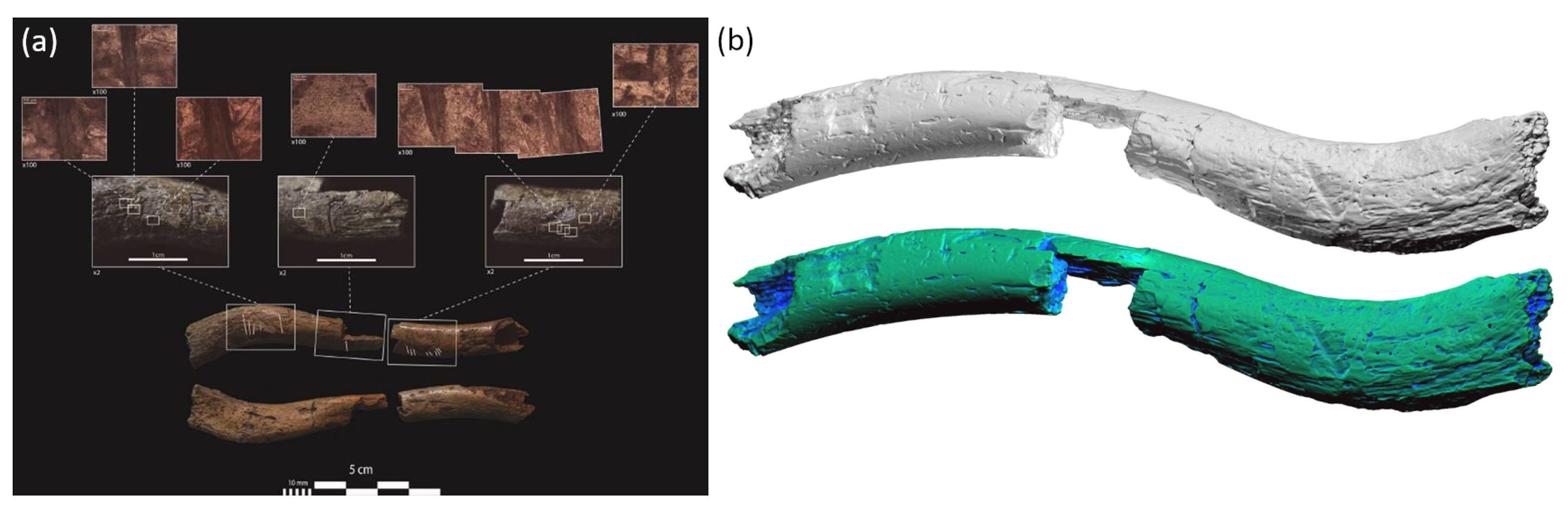
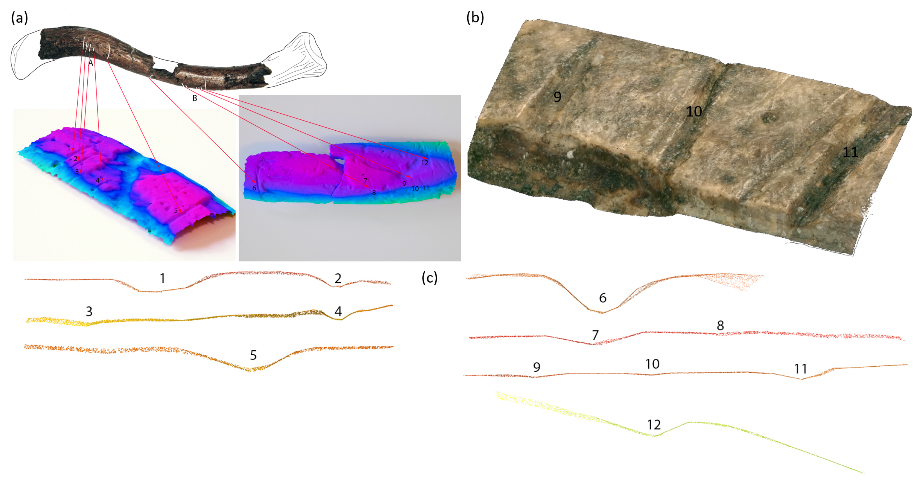
4.1. Locations of Cuts
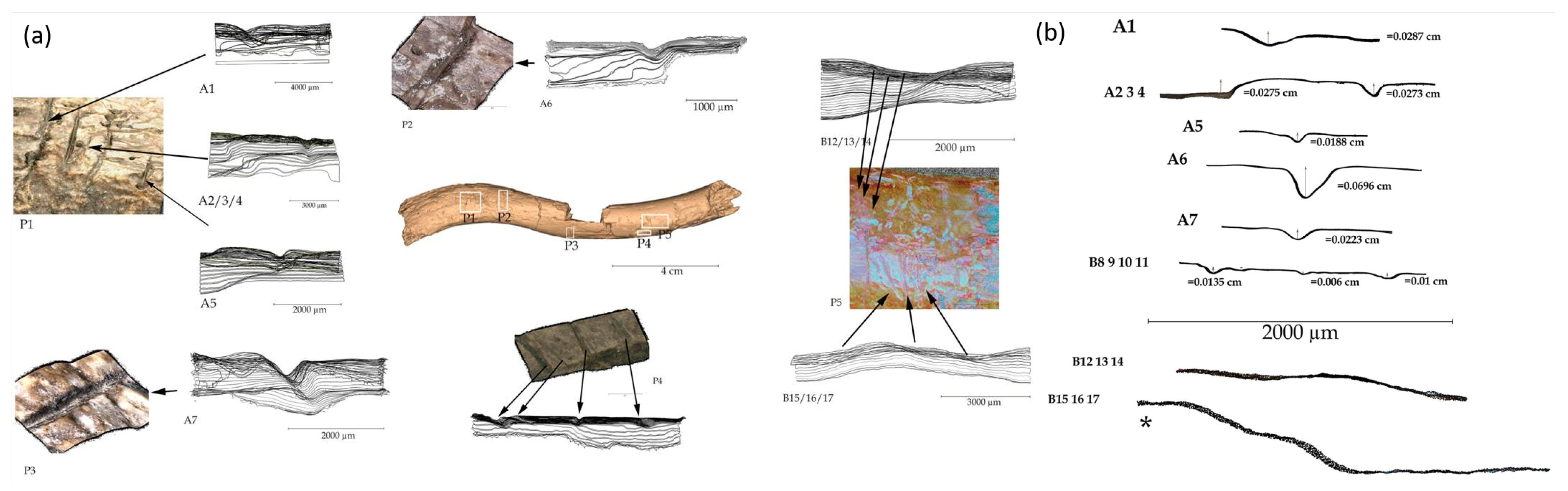
4.2. Morphological Analysis
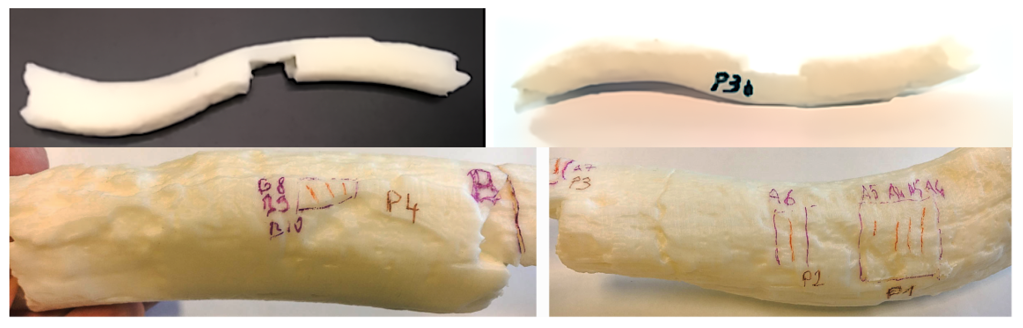
4.3. 3D Printing
5. Discussion
6. Conclusions
Author Contributions
Funding
Acknowledgments
Conflicts of Interest
References
- Adamopoulos, E.; Rinaudo, F.; Ardissono, L. A critical comparison of 3D digitization techniques for heritage objects. ISPRS Int. J. Geo-Inf. 2021, 10, 10. [Google Scholar] [CrossRef]
- Miccichè, R.; Carotenuto, G.; Sìneo, L. The utility of 3D medical imaging techniques for obtaining a reliable differential diagnosis of metastatic cancer in an Iron Age skull. Int. J. Paleopathol. 2018, 21, 41–46. [Google Scholar] [CrossRef] [PubMed]
- Villa, C.; Frohlich, B.; Lynnerup, N. The Role of Imaging in Paleopathology. In Ortner’s Identification of Pathological Conditions in Human Skeletal Remains; Elsevier: Amsterdam, The Netherlands, 2019; pp. 169–182. [Google Scholar]
- Beer, S. Digital heritage museums and virtual museums. In Proceedings of the 2015 Virtual Reality International Conference, Laval, France, 8–10 April 2015; pp. 1–4. [Google Scholar]
- Bérubé, P. Vers une Muséographie Numérique: L’Impression 3D en tant que Dispositif de Traduction auprès de Publics Malvoyants et Aveugles. Master’s Thesis, Université de Montréal, Montreal, QC, Canada, 2018. [Google Scholar]
- Kuzminsky, S.C.; Gardiner, M.S. Three-dimensional laser scanning: Potential uses for museum conservation and scientific research. J. Archaeol. Sci. 2012, 39, 2744–2751. [Google Scholar] [CrossRef]
- Budak, I.; Santosi, Z.; Stojakovic, V.; Korolija Crkvenjakov, D.; Obradovic, R.; Milosevic, M.; Sokac, M. Development of Expert System for the Selection of 3D Digitization Method in Tangible Cultural Heritage. Teh. Vjesn. 2019, 26, 837–844. [Google Scholar]
- Falkingham, P.L. Acquisition of high resolution three-dimensional models using free, open-source, photogrammetric software. Palaeontol. Electron. 2012, 15, 15. [Google Scholar] [CrossRef]
- Yravedra, J.; Maté-González, M.Á.; Courtenay, L.A.; López-Cisneros, P.; Estaca-Gómez, V.; Aramendi, J.; de Andrés-Herrero, M.; Linares-Matás, G.; Aguilera, D.G.; Álvarez-Alonso, D. Approaching raw material functionality in the Upper Magdalenian of Coímbre cave (Asturias, Spain) through geometric morphometrics. Quat. Int. 2019, 517, 97–106. [Google Scholar] [CrossRef]
- Niven, L.; Steele, T.E.; Finke, H.; Gernat, T.; Hublin, J.J. Virtual skeletons: Using a structured light scanner to create a 3D faunal comparative collection. J. Archaeol. Sci. 2009, 36, 2018–2023. [Google Scholar] [CrossRef]
- Errickson, D.; Grueso, I.; Griffith, S.; Setchell, J.; Thompson, T.; Thompson, C.; Gowland, R.L. Towards a Best Practice for the Use of Active Non-contact Surface Scanning to Record Human Skeletal Remains from Archaeological Contexts. Int. J. Osteoarchaeol. 2017, 27, 650–661. [Google Scholar] [CrossRef]
- Maté-González, M.Á.; Courtenay, L.A.; Aramendi, J.; Yravedra, J.; Mora, R.; González-Aguilera, D.; Domínguez-Rodrigo, M. Application of geometric morphometrics to the analysis of cut mark morphology on different bones of differently sized animals. Does size really matter? Quat. Int. 2019, 517, 33–44. [Google Scholar] [CrossRef]
- Rodríguez-Alba, J.J.; Linares-Matás, G.; Yravedra, J. First assessments of the taphonomic behaviour of jaguar (Panthera onca). Quat. Int. 2019, 517, 88–96. [Google Scholar] [CrossRef]
- Arriaza, M.C.; Aramendi, J.; Maté-González, M.Á.; Yravedra, J.; Baquedano, E.; González-Aguilera, D.; Domínguez-Rodrigo, M. Geometric-morphometric analysis of tooth pits and the identification of felid and hyenid agency in bone modification. Quat. Int. 2019, 517, 79–87. [Google Scholar] [CrossRef]
- Aramendi, J.; Arriaza, M.C.; Yravedra, J.; Maté-González, M.Á.; Ortega, M.C.; Courtenay, L.A.; González-Aguilera, D.; Gidna, A.; Mabulla, A.; Baquedano, E.; et al. Who ate OH80 (Olduvai Gorge, Tanzania)? A geometric-morphometric analysis of surface bone modifications of a Paranthropus boisei skeleton. Quat. Int. 2019, 517, 118–130. [Google Scholar] [CrossRef]
- Papageorgopoulou, C.; Kuhn, G.; Ziegler, U.; Rühli, F.J. Diagnostic morphometric applicability of confocal laser scanning microscopy in Osteoarchaeology. Int. J. Osteoarchaeol. 2010, 20, 708–718. [Google Scholar] [CrossRef]
- Boschin, F.; Zanolli, C.; Bernardini, F.; Princivalle, F.; Tuniz, C. A look from the inside: microCT analysis of burned bones. Ethnobiol. Lett. 2015, 6, 258–266. [Google Scholar] [CrossRef]
- Uldin, T. Virtual anthropology—A brief review of the literature and history of computed tomography. Forensic Sci. Res. 2017, 2, 165–173. [Google Scholar] [CrossRef] [PubMed]
- Galantucci, L.M.; Guerra, M.G.; Lavecchia, F. Photogrammetry applied to small and micro scaled objects: A review. In Proceedings of the International Conference on the Industry 4.0 Model for Advanced Manufacturing, Belgrade, Serbia, 1–4 June 2020; Springer: Berlin/Heidelberg, Germany, 2020; pp. 57–77. [Google Scholar]
- Peacock, E.; Ryan, T.M. Scaling up, scaling down: Experiments with high resolution computed tomography scanning of microartefacts. Acta Archaeol. 2018, 89, 193–206. [Google Scholar] [CrossRef]
- Braga, J.; Zimmer, V.; Dumoncel, J.; Samir, C.; De Beer, F.; Zanolli, C.; Pinto, D.; Rohlf, F.J.; Grine, F.E. Efficacy of diffeomorphic surface matching and 3D geometric morphometrics for taxonomic discrimination of Early Pleistocene hominin mandibular molars. J. Hum. Evol. 2019, 130, 21–35. [Google Scholar] [CrossRef]
- Rosell, J.; Blasco, R.; Arilla, M.; Fernández-Jalvo, Y. Very human bears: Wild brown bear neo-taphonomic signature and its equifinality problems in archaeological contexts. Quat. Int. 2019, 517, 67–78. [Google Scholar] [CrossRef]
- Linares-Matás, G.J.; Yravedra, J.; Maté-González, M.Á.; Courtenay, L.A.; Aramendi, J.; Cuartero, F.; González-Aguilera, D. A geometric-morphometric assessment of three-dimensional models of experimental cut-marks using flint and quartzite flakes and handaxes. Quat. Int. 2019, 517, 45–54. [Google Scholar] [CrossRef]
- López-Cisneros, P.; Linares-Matás, G.; Yravedra, J.; Maté-González, M.Á.; Estaca-Gómez, V.; Mora, R.; Aramendi, J.; Asensio, J.A.R.; Barrera-Logares, J.M.; Aguilera, D.G. Applying new technologies to the taphonomic study of La Lluera (Asturias, Spain). Geometric morphometrics and the study of bone surface modifications (BSM). Quat. Int. 2019, 517, 107–117. [Google Scholar] [CrossRef]
- Courtenay, L.A.; Yravedra, J.; Huguet, R.; Ollé, A.; Aramendi, J.; Maté-González, M.Á.; González-Aguilera, D. New taphonomic advances in 3D digital microscopy: A morphological characterisation of trampling marks. Quat. Int. 2019, 517, 55–66. [Google Scholar] [CrossRef]
- Bello, S.M.; Galway-Witham, J. Bone taphonomy inside and out: Application of 3-dimensional microscopy, scanning electron microscopy and micro-computed tomography to the study of humanly modified faunal assemblages. Quat. Int. 2019, 517, 16–32. [Google Scholar] [CrossRef]
- Maté-González, M.Á.; González-Aguilera, D.; Linares-Matás, G.; Yravedra, J. New technologies applied to modelling taphonomic alterations. Quat. Int. 2019, 517, 4–15. [Google Scholar] [CrossRef]
- Cunningham, J.A.; Rahman, I.A.; Lautenschlager, S.; Rayfield, E.J.; Donoghue, P.C. A virtual world of paleontology. Trends Ecol. Evol. 2014, 29, 347–357. [Google Scholar] [CrossRef]
- Robedizo, B.P. The identifiability of Osteological Traits on 3D Models of Human Skeletal Remains. Master’s Thesis, Lund University, Lund, Sweden, 2016. [Google Scholar]
- Gamble, J.; Blackburn, A.; Hoppa, R.D. Congruence of Methods for Determination of Sex using Real, Virtual and 3-D Printed Specimens. Revive Past 2011, 132. [Google Scholar] [CrossRef]
- Barreau, J.B.; Le Maire, M.; Bourbouze, G. Study of the identity of a Breton mammoth from flattened tusk pieces tomography. In Proceedings of the 26th EAA Annual Meeting, Budapest, Hungary, 26–30 August 2020. [Google Scholar]
- Urbanová, P.; Ross, A.H.; Jurda, M.; Šplíchalová, I. The virtual approach to the assessment of skeletal injuries in human skeletal remains of forensic importance. J. Forensic Leg. Med. 2017, 49, 59–75. [Google Scholar] [CrossRef] [PubMed]
- Martisius, N.L.; Sidéra, I.; Grote, M.N.; Steele, T.E.; McPherron, S.P.; Schulz-Kornas, E. Time wears on: Assessing how bone wears using 3D surface texture analysis. PLoS ONE 2018, 13, e0206078. [Google Scholar] [CrossRef]
- Dellù, E.; Sciatti, A. Care of ancient human remains. Conservation and management with 3d modeling and dbms. In Proceedings of the ARQUEOLÓGICA 2.0-9th International Congress & 3rd GEORES-GEOmatics and pREServation, Valencia, Spain, 26–28 April 2021; pp. 414–426. [Google Scholar]
- Hassett, B.R. Which Bone to Pick: Creation, Curation, and Dissemination of Online 3D Digital Bioarchaeological Data. Archaeologies 2018, 14, 231–249. [Google Scholar] [CrossRef]
- Figueiredo, E.; Silva, R.J.; Araújo, M.F.; Fernandes, F.M.B. Multifocus optical microscopy applied to the study of archaeological metals. Microsc. Microanal. 2013, 19, 1248–1254. [Google Scholar] [CrossRef]
- Zotkina, L. Le bison de La Grèze (Marquay, Dordogne, France) sous le microscope. PALEO Rev. D’Archeologie Prehist. 2016, 27, 307–320. [Google Scholar] [CrossRef]
- Duches, R.; Nannini, N.; Romandini, M.; Boschin, F.; Crezzini, J.; Peresani, M. Identification of Late Epigravettian hunting injuries: Descriptive and 3D analysis of experimental projectile impact marks on bone. J. Archaeol. Sci. 2016, 66, 88–102. [Google Scholar] [CrossRef]
- Moretti, E.; Arrighi, S.; Boschin, F.; Crezzini, J.; Aureli, D.; Ronchitelli, A. Using 3D microscopy to analyze experimental cut marks on animal bones produced with different stone tools. Ethnobiol. Lett. 2015, 6, 267–275. [Google Scholar] [CrossRef]
- Bello, S.M.; De Groote, I.; Delbarre, G. Application of 3-dimensional microscopy and micro-CT scanning to the analysis of Magdalenian portable art on bone and antler. J. Archaeol. Sci. 2013, 40, 2464–2476. [Google Scholar] [CrossRef]
- Lyman, R.L. Archaeofaunas and butchery studies: A taphonomic perspective. Adv. Archaeol. Method Theory 1987, 10, 249–337. [Google Scholar]
- Domínguez-Rodrigo, M.; Saladié, P.; Cáceres, I.; Huguet, R.; Yravedra, J.; Rodríguez-Hidalgo, A.; Martín, P.; Pineda, A.; Marín, J.; Gené, C.; et al. Use and abuse of cut mark analyses: The Rorschach effect. J. Archaeol. Sci. 2017, 86, 14–23. [Google Scholar] [CrossRef]
- Maté-González, M.Á.; Aramendi, J.; González-Aguilera, D.; Yravedra, J. Statistical comparison between low-cost methods for 3D characterization of cut-marks on bones. Remote Sens. 2017, 9, 873. [Google Scholar] [CrossRef]
- Fantini, M.; de Crescenzio, F.; Persiani, F.; Benazzi, S.; Gruppioni, G. 3D restitution, restoration and prototyping of a medieval damaged skull. Rapid Prototyp. J. 2008, 14, 318–324. [Google Scholar] [CrossRef]
- Been, E.; Gómez-Olivencia, A.; Kramer, P.A.; Barash, A. 3D reconstruction of spinal posture of the Kebara 2 Neanderthal. In Human Paleontology and Prehistory; Springer: Berlin/Heidelberg, Germany, 2017; pp. 239–251. [Google Scholar]
- Allard, T.T. The Role of 3D Printing in Biological Anthropology. Master’s Thesis, University of Manitoba, Winnipeg, Manitoba, 2006. [Google Scholar]
- Almeida, F.; Bártolo, P.; Alves, N.; Almeida, H.; Ponce de Léon, M.; Zollikofer, C.; Pierson, B.; Serra, P.; Duarte, C.; Trinkaus, E.; et al. The Lapedo Child Reborn: Contributions of CT Scanning and Rapid Prototyping for an Upper Paleolithic Infant Burial and Face Reconstruction. The Case of Lagar Velho Interpretation Centre, Leiria, Portugal. In VAST 2007: Future Technologies to Empower Heritage Professionals: Short and Project Papers from Vast2007; EPOCH Publication: Archaeolingua, Budapest, 2007; pp. 69–73. [Google Scholar]
- Fiorenza, L.; Yong, R.; Ranjitkar, S.; Hughes, T.; Quayle, M.; McMenamin, P.G.; Kaidonis, J.; Townsend, G.C.; Adams, J.W. The use of 3D printing in dental anthropology collections. Am. J. Phys. Anthropol. 2018, 167, 400–406. [Google Scholar] [CrossRef]
- Mafart, B.Y.; Delingette, H.; Subsol, G. Three-Dimensional Imaging in Paleoanthropology and Prehistoric Archaeology; Archaeopress: Oxford, UK, 2002. [Google Scholar]
- Turner-Walker, G. The chemical and microbial degradation of bones and teeth. Adv. Hum. Palaeopathol. 2008, 592, 3–29. [Google Scholar]
- Marchand, G.; Dupont, C.; Laforge, M.; Le Bannier, J.C.; Netter, C.; Nukushina, D.; Onfray, M.; Querré, G.; Quesnel, L.; Stéphan, P. Before the spatial analysis of Beg-er-Vil: A journey through the multiple archaeological dimensions of a Mesolithic dwelling in Atlantic France. J. Archaeol. Sci. Rep. 2018, 18, 973–983. [Google Scholar] [CrossRef]
- Marchand, G.; Dupont, C. Domestic life by the ocean: Beg-er-Vil, c. 6200–6000 cal BC. In Foraging Assemblages; Borić, D., Antonović, D., Mihailović, B., Eds.; Serbian Archaeological Society: Belgrade, Serbia; The Italian Academy for Advanced Studies in America, Columbia University: New York, NY, USA, 2021; Volume 1, pp. 191–197. [Google Scholar]
- Clarke, D.L. Analytical Archaeology; Columbia University Press: New York, NY, USA, 1978. [Google Scholar]
- Rozoy, J.G. Les Derniers Chasseurs: L’Epipaléolithique en France et en Belgique: Essai de Synthèse; Cambridge University Press: London, UK, 1978; Volume 2. [Google Scholar]
- Dupont, C.; Marchand, G.; Carrión Marco, Y.; Desse-Berset, N.; Gaudin, L.; Gruet, Y.; Marguerie, D.; Oberlin, C. Beg-an-Dorchenn (Plomeur, Finistère): Une fenêtre ouverte sur l’exploitation du littoral par les peuples mésolithiques du VI e millénaire dans l’Ouest de la France. In Bulletin de la Société préhistorique Française; Société Préhistorique Française: Paris, France, 2010; pp. 227–290. [Google Scholar]
- Dupont, C.; Marchand, G. New paradigms in the exploitation of Mesolithic shell middens in Atlantic France: The example of Beg-er-Vil, Brittany. Quat. Int. 2021, 584, 59–71. [Google Scholar] [CrossRef]
- Péquart, M.; Péquart, S.J.; Boule, M.; Vallois, H.V. Téviec, Station-Nécrolopole Mésolithique du Morbihan; Masson et Cie: Echandens, Switzerland, 1937. [Google Scholar]
- Bello, S.M.; Wallduck, R.; Dimitrijević, V.; Živaljević, I.; Stringer, C.B. Cannibalism versus funerary defleshing and disarticulation after a period of decay: Comparisons of bone modifications from four prehistoric sites. Am. J. Phys. Anthropol. 2016, 161, 722–743. [Google Scholar] [CrossRef] [PubMed]
- Boulestin, B. Approche Taphonomique des Restes Humains: Le cas des Mésolithiques de la Grotte des Perrats (Agris, Charente). In Bulletin de la Société préhistorique française; Archaeopress: Oxford, UK, 1998. [Google Scholar]
- Jackes, M.K. Osteological evidence for Mesolithic and Neolithic violence: Problems of interpretation. BAR Int. Ser. 2004, 1237, 23–40. [Google Scholar]
- Tung, T.A. Dismembering bodies for display: A bioarchaeological study of trophy heads from the Wari site of Conchopata, Peru. Am. J. Phys. Anthropol. 2008, 136, 294–308. [Google Scholar] [CrossRef] [PubMed]
- Gresky, J.; Haelm, J.; Clare, L. Modified human crania from Göbekli Tepe provide evidence for a new form of Neolithic skull cult. Sci. Adv. 2017, 3, e1700564. [Google Scholar] [CrossRef]
- Olsen, S.L.; Shipman, P. Surface modification on bone: Trampling versus butchery. J. Archaeol. Sci. 1988, 15, 535–553. [Google Scholar] [CrossRef]
- Králík, M.; Urbanová, P.; Wagenknechtová, M. Sex assessment using clavicle measurements: Inter-and intra-population comparisons. Forensic Sci. Int. 2014, 234, 181-e1. [Google Scholar] [CrossRef]
- Akhlaghi, M.; Moradi, B.; Hajibeygi, M. Sex determination using anthropometric dimensions of the clavicle in Iranian population. J. Forensic Leg. Med. 2012, 19, 381–385. [Google Scholar] [CrossRef]
- Dehiya, A.; Agnihotri, G.; Sharma, R.K. Morphometric Variation of Adult Human Clavicle-A Tool for Gender Determination. Int. J. Med. Dent. Sci. 2019, 8, 1793–1799. [Google Scholar]
- Gaugne, R.; Nicolas, T.; Barreau, J.B.; Marchand, G.; Auger, R.; Francus, P.; Gouranton, V. Méthodes d’introspection numérique pour les objets archéologiques. In Proceedings of the GMPCA 2017-XXIème Colloque International du Groupe des Méthodes Pluridisciplinaires Contribuant à l’Archéologie, Rennes, France, 21 April 2017. [Google Scholar]
- Girardeau-Montaut, D. CloudCompare; EDF R&D Telecom ParisTech: Palaiseau, France, 2016. [Google Scholar]
- Mackey, T.J.; Sumner, D.Y.; Hawes, I.; Jungblut, A.D. Morphological signatures of microbial activity across sediment and light microenvironments of Lake Vanda, Antarctica. Sediment. Geol. 2017, 361, 82–92. [Google Scholar] [CrossRef]
- Högberg, A.; Brink, K.; Grandin, L.; Horn, C. A silver-coated copper axe from Late Neolithic Scania: Initial analyses. Fornvännen 2016, 111, 258–264. [Google Scholar]
- Keyence, C. Digital Microscope VHX-5000 User’s Manual. 2014. Available online: http://uhulag.mendelu.cz/files/pagesdata/cz/biometrickalaborator/vhx-5000_user-manual.pdf (accessed on 20 January 2022).
- Medina-Alcaide, M.Á.; Maidagan, D.G.; Torti, J.L.S. Painted in red: In search of alternative explanations for European Palaeolithic cave art. Quat. Int. 2018, 491, 65–77. [Google Scholar] [CrossRef]
- Caffesse, R.G.; Burgett, F.G.; Nasjleti, C.E.; Castelli, W.A. Healing of Free Gingival Grafts With and Without Periosteum: Part I. Histologic Evaluation. J. Periodontol. 1979, 50, 586–594. [Google Scholar] [CrossRef] [PubMed]
- Delagnes, A.; Lenoble, A.; Harmand, S.; Brugal, J.P.; Prat, S.; Tiercelin, J.J.; Roche, H. Interpreting pachyderm single carcass sites in the African Lower and Early Middle Pleistocene record: A multidisciplinary approach to the site of Nadung’a 4 (Kenya). J. Anthropol. Archaeol. 2006, 25, 448–465. [Google Scholar] [CrossRef]
- Flohr, T.; Küttner, A.; Bruder, H.; Stierstorfer, K.; Halliburton, S.S.; Schaller, S.; Ohnesorge, B.M. Performance evaluation of a multi-slice CT system with 16-slice detector and increased gantry rotation speed for isotropic submillimeter imaging of the heart. Herz 2003, 28, 7–19. [Google Scholar] [CrossRef] [PubMed]
- Colleter, R.; Adèle, P.A. Les restes humains archéologiques en France: Entre objets de science et sujets de droit. Can. J. Bioethics/Revue Can. BioéThique 2019, 2, 97–108. [Google Scholar] [CrossRef][Green Version]
- Kuefner, M.; Brand, M.; Engert, C.; Schwab, S.; Uder, M. Radiation induced DNA double-strand breaks in radiology. In RöFo-Fortschritte auf dem Gebiet der Röntgenstrahlen und der bildgebenden Verfahren; Georg Thieme Verlag KG: New York, NY, USA, 2015; Volume 187, pp. 872–878. [Google Scholar]
- Dickin, F.; Pollard, S.; Adams, G. Mapping and correcting the distortion of 3D structured light scanners. Precis. Eng. 2021, 72, 543–555. [Google Scholar] [CrossRef]
- Garashchenko, Y.; Kogan, I.; Rucki, M. Comparative accuracy analysis of triangulated surface models of a fossil skull digitized with various optic devices. Metrol. Meas. Syst. 2022, 29. [Google Scholar] [CrossRef]
- AbouHashem, Y.; Dayal, M.; Savanah, S.; Štrkalj, G. The application of 3D printing in anatomy education. Med. Educ. Online 2015, 20, 29847. [Google Scholar] [CrossRef]
- Mahmoud, A.; Bennett, M. Introducing 3-dimensional printing of a human anatomic pathology specimen: Potential benefits for undergraduate and postgraduate education and anatomic pathology practice. Arch. Pathol. Lab. Med. 2015, 139, 1048–1051. [Google Scholar] [CrossRef]
- Schuh, A.; Dutailly, B.; Coutinho Nogueira, D.; Santos, F.; Vandermeersch, B.; Coqueugniot, H.; Tillier, A.M.; Arensburg, B. La mandibule de l’adulte Qafzeh 25 (Paléolithique moyen), Basse Galilée, Reconstruction virtuelle 3D et analyse morphométrique. Paléorient 2017, 43, 49–59. [Google Scholar] [CrossRef]
- El Beheiry, M.; Doutreligne, S.; Caporal, C.; Ostertag, C.; Dahan, M.; Masson, J.B. Virtual reality: Beyond visualization. J. Mol. Biol. 2019, 431, 1315–1321. [Google Scholar] [PubMed]


| Bone | 56-186-007-AG-22-122 | 56-186-007-AG-23-173 | |||||
|---|---|---|---|---|---|---|---|
| Chunk | 1 | 2 | 3 | Total | 1 | 2 | Total |
| Cameras aligned | 44/44 | 33/33 | 44/44 | 121/121 | 52/52 | 42/42 | 94/94 |
| Tie points | 4829 | 4999 | 4766 | 14,594 | 5314 | 5477 | 10,791 |
| Dense cloud points | 3,984,146 | 3,528,415 | 4,087,049 | 11,599,610 | 3,300,123 | 3,746,140 | 7,046,263 |
| 3D model faces | 802,323 | 235,800 | 274,280 | 1,312,403 | 221,999 | 250,546 | 472,545 |
| Photometric Interpretation | Rows | Columns | Pixel Spacing | Bits Allocated | Bits Stored | High Bit | Rescale Intercept | Rescale Slope | |
|---|---|---|---|---|---|---|---|---|---|
| CT | MONO CHROME2 | 484 | 484 | 0.110743\ 0.110743 | 16 | 12 | 11 | −1024 | 1 |
| µ-CT | MONO CHROME2 | 346 | 466 | 0.078102\ 0.078102 | 16 | 16 | 15 | 0 | 1 |
Publisher’s Note: MDPI stays neutral with regard to jurisdictional claims in published maps and institutional affiliations. |
© 2022 by the authors. Licensee MDPI, Basel, Switzerland. This article is an open access article distributed under the terms and conditions of the Creative Commons Attribution (CC BY) license (https://creativecommons.org/licenses/by/4.0/).
Share and Cite
Barreau, J.-B.; Gagnier, A.; Gaugne, R.; Marchand, G.; Gómez, J.C.; Gouranton, V.; Colleter, R. Use of Different Digitization Methods for the Analysis of Cut Marks on the Oldest Bone Found in Brittany (France). Appl. Sci. 2022, 12, 1381. https://doi.org/10.3390/app12031381
Barreau J-B, Gagnier A, Gaugne R, Marchand G, Gómez JC, Gouranton V, Colleter R. Use of Different Digitization Methods for the Analysis of Cut Marks on the Oldest Bone Found in Brittany (France). Applied Sciences. 2022; 12(3):1381. https://doi.org/10.3390/app12031381
Chicago/Turabian StyleBarreau, Jean-Baptiste, Adeline Gagnier, Ronan Gaugne, Grégor Marchand, Jorge Calvo Gómez, Valérie Gouranton, and Rozenn Colleter. 2022. "Use of Different Digitization Methods for the Analysis of Cut Marks on the Oldest Bone Found in Brittany (France)" Applied Sciences 12, no. 3: 1381. https://doi.org/10.3390/app12031381
APA StyleBarreau, J.-B., Gagnier, A., Gaugne, R., Marchand, G., Gómez, J. C., Gouranton, V., & Colleter, R. (2022). Use of Different Digitization Methods for the Analysis of Cut Marks on the Oldest Bone Found in Brittany (France). Applied Sciences, 12(3), 1381. https://doi.org/10.3390/app12031381