
CRCSI: A Generic Block Interleaver for the Next Generation Terrestrial Broadcast Systems


Abstract
1. Introduction
2. System Model
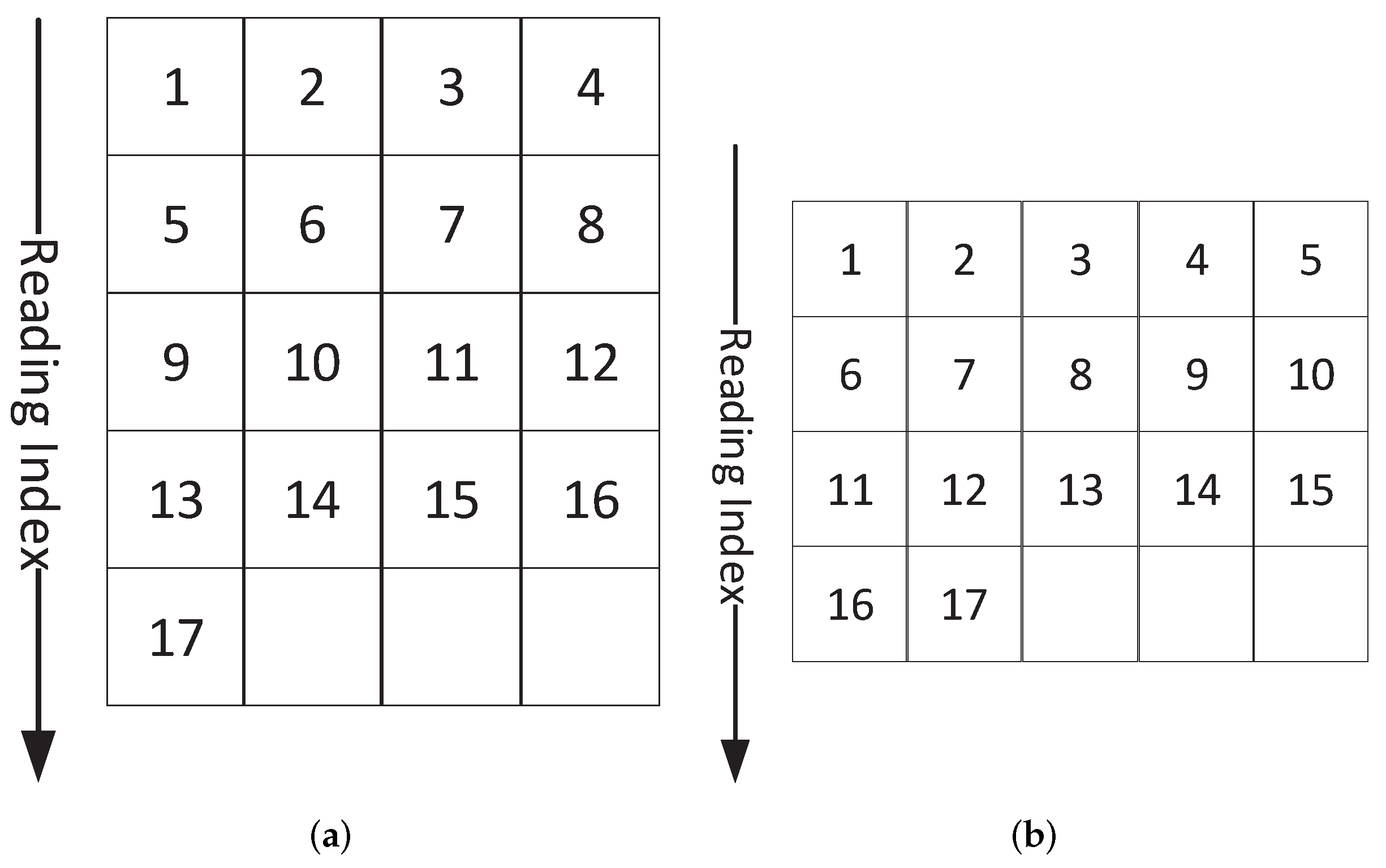
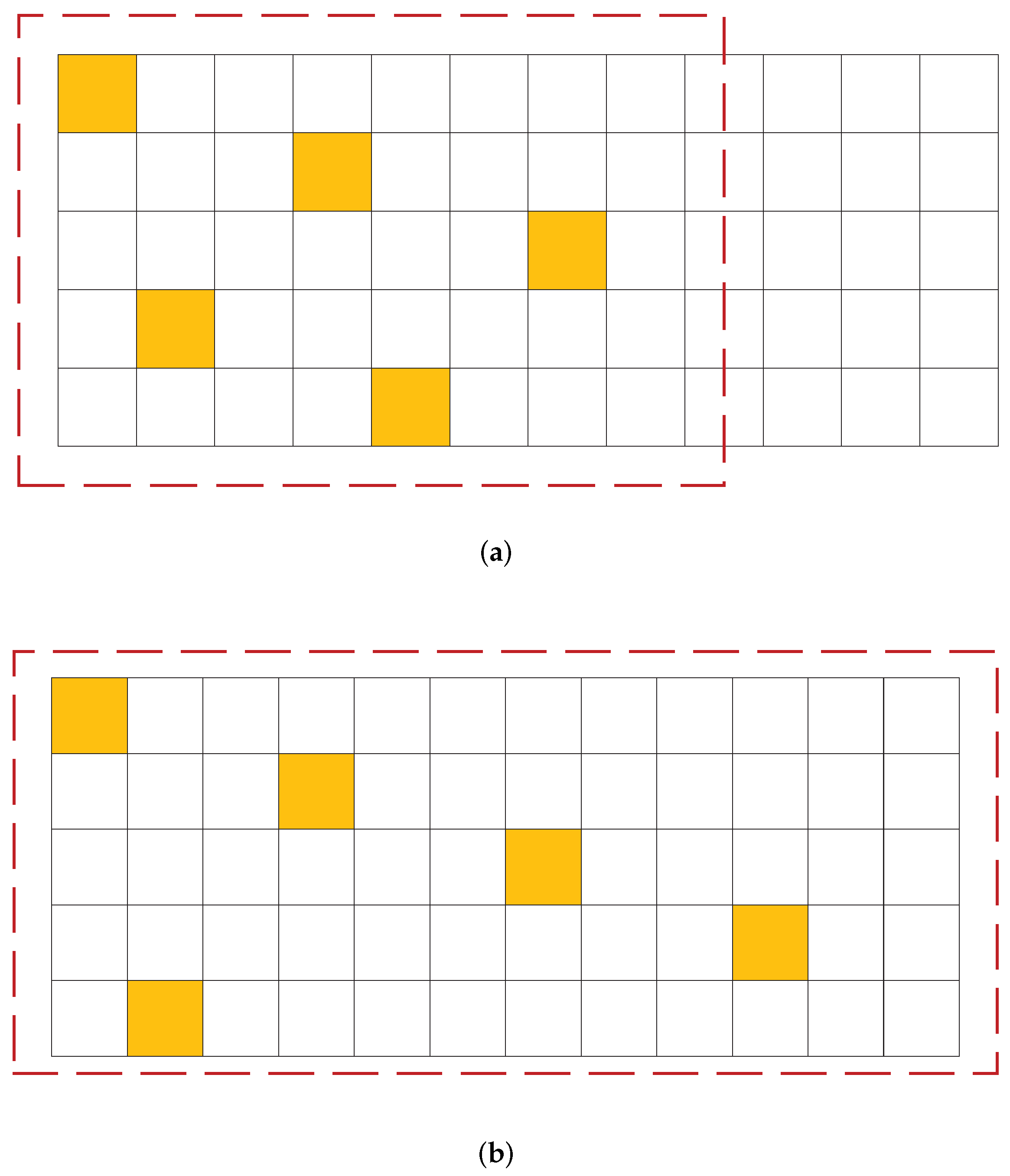
2.1. Block Interleaving
2.2. Performance Indicator
2.3. Problem Formulation
2.3.1. Incremental Interval p
2.3.2. Predefined Shift Vector
3. Designing the Block Interleaver
3.1. Interleaver Structure
- Each sequence is sorted at an appropriate interval to increase the interleaving distance;
- Adjacent sub-carriers in the same OFDM symbol are spaced as evenly as possible;
- The shift period of the OFDM symbol is extended in a two-dimensional manner to obtain the time diversity;
- Reading order is determined by the result of joint processing.
3.2. CRCSI Design
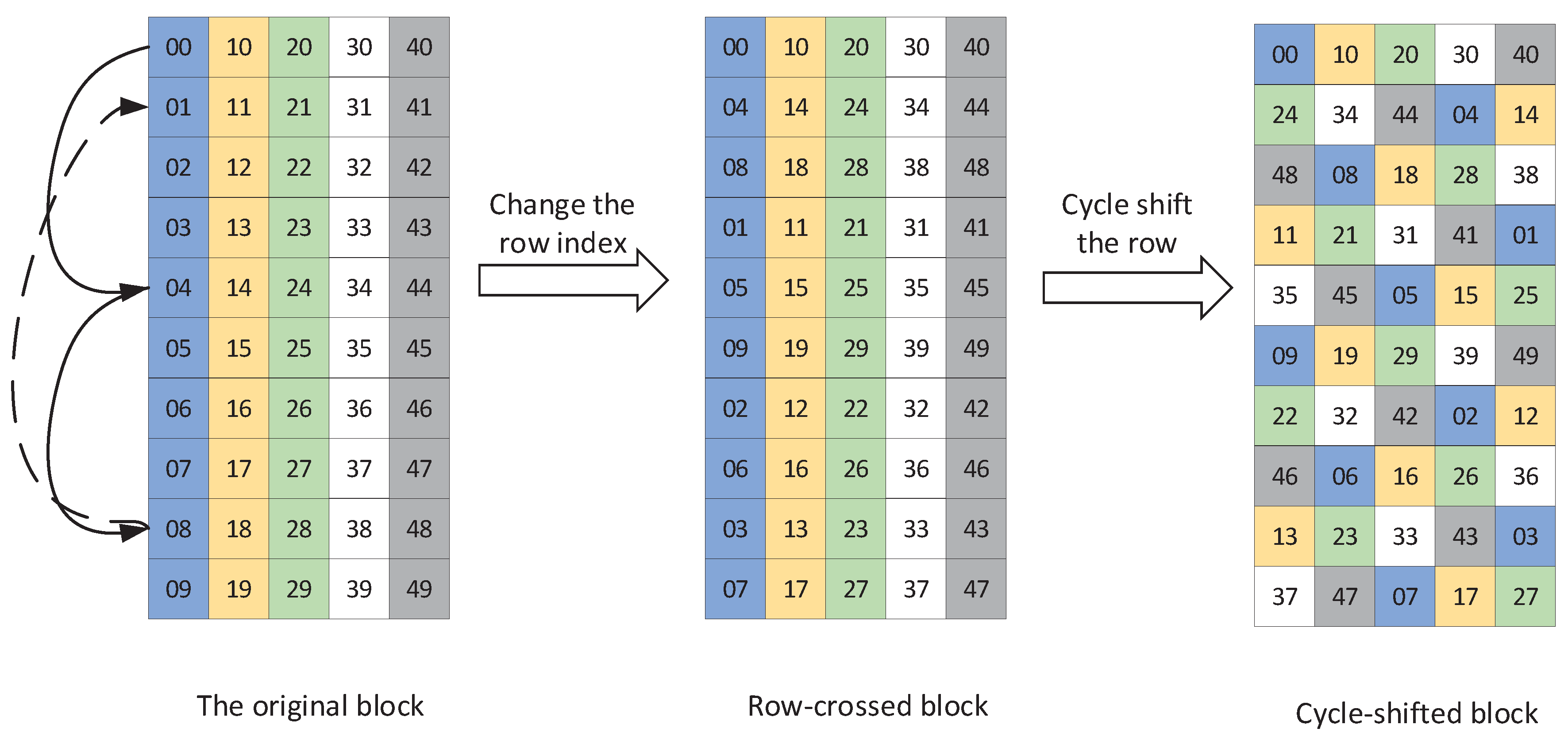
3.2.1. Row Crossing
- p is a prime number of M,
- p is a common divisor of M,where . For example, for a block, the group size is , and the incremental interval is , hence, the row index is .
3.2.2. Cyclic Shift
4. Simulation Results
4.1. Simulation Parameters
4.2. Theoretical Results
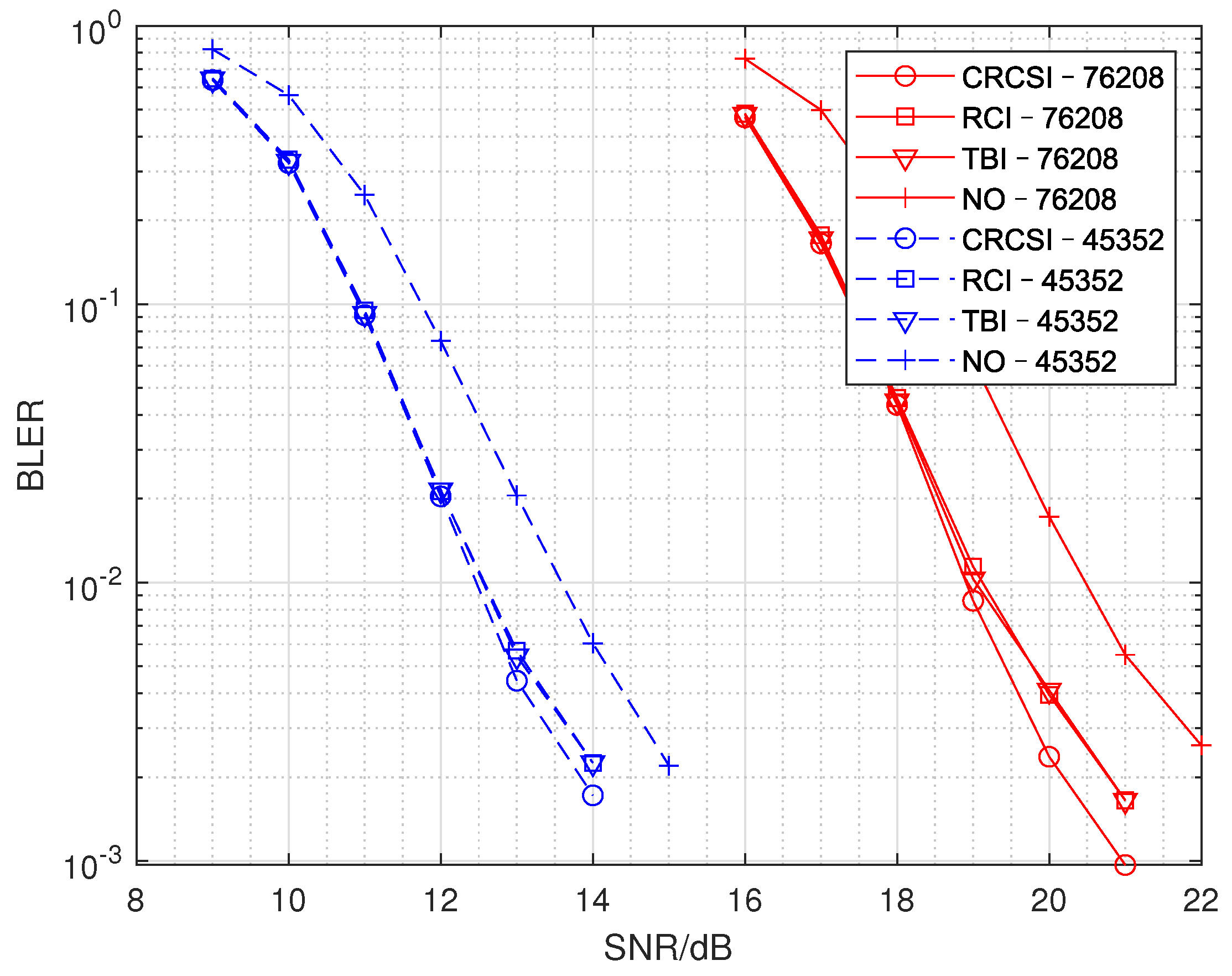
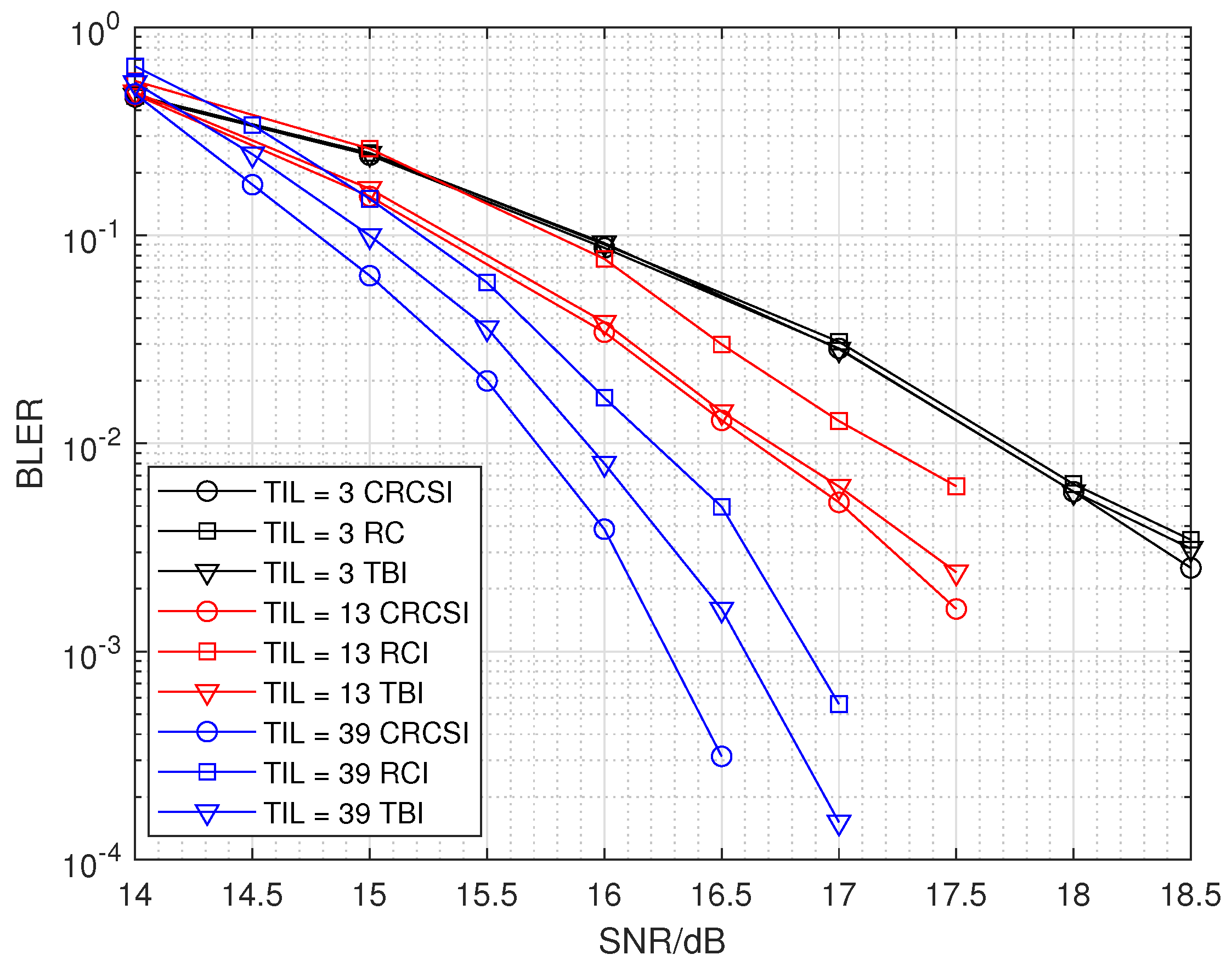
4.3. Link-Level Simulation Results
5. Conclusions
Author Contributions
Funding
Institutional Review Board Statement
Informed Consent Statement
Data Availability Statement
Acknowledgments
Conflicts of Interest
References
- Mansour, M.M. Pruned Bit-Reversal Permutations: Mathematical Characterization, Fast Algorithms and Architectures. IEEE Trans. Signal Process. 2013, 61, 3081–3099. [Google Scholar] [CrossRef][Green Version]
- Ould-Cheikh-Mouhamedou, Y. A Simple and Efficient Method for Lowering the Error Floors of Turbo Codes that Use Structured Interleavers. IEEE Commun. Lett. 2012, 16, 392–395. [Google Scholar] [CrossRef]
- Sreedevi, M.; Yamuna, B.; Salija, P. Design and Implementation of Interleaver in GNU Radio for short block length Turbo codes. In Proceedings of the 2019 9th International Conference on Advances in Computing and Communication (ICACC), Kochi, India, 6–8 November 2019; pp. 17–21. [Google Scholar]
- Garzon Bohorquez, R.; Nour, C.A.; Douillard, C. On the Equivalence of Interleavers for Turbo Codes. IEEE Wirel. Commun. Lett. 2015, 4, 58–61. [Google Scholar] [CrossRef][Green Version]
- Takeshita, O.Y. On maximum contention-free interleavers and permutation polynomials over integer rings. IEEE Trans. Inf. Theory 2006, 52, 1249–1253. [Google Scholar] [CrossRef]
- Crozier, S.; Guinand, P. High-performance low-memory interleaver banks for turbo-codes. In Proceedings of the IEEE 54th Vehicular Technology Conference. VTC Fall 2001. Proceedings (Cat. No.01CH37211), Atlantic City, NJ, USA, 7–11 October 2001; Volume 4, pp. 2394–2398. [Google Scholar]
- Garello, R.; Pierleoni, P.; Benedetto, S. Computing the free distance of turbo codes and serially concatenated codes with interleavers: Algorithms and applications. IEEE J. Sel. Areas Commun. 2001, 19, 800–812. [Google Scholar] [CrossRef]
- Garzon Bohorquez, R.; Nour, C.A.; Douillard, C. Channel Interleavers for Terrestrial Broadcast: Analysis and Design. IEEE Trans. Broadcast. 2014, 60, 679–692. [Google Scholar] [CrossRef]
- Eizmendi, I.; Velez, M.; Gomez-Barquero, D.; Morgade, J.; Zoellner, J. DVB-T2: The Second Generation of Terrestrial Digital Video Broadcasting System. IEEE Trans. Broadcast. 2014, 60, 258–271. [Google Scholar] [CrossRef]
- Klenner, P.; Baek, J.S.; Loghin, N.S.; Gomez-Barquero, D.; Ko, W.S. Physical Layer Time Interleaving for the ATSC 3.0 System. IEEE Trans. Broadcast. 2016, 62, 253–262. [Google Scholar] [CrossRef]
- Xu, W.Q.; Golomb, S.W. Optimal 2-D Interleaving With Latin Rectangles. IEEE Trans. Broadcast. 2005, 51, 1179–1182. [Google Scholar] [CrossRef]
- Zhang, X.M.; Xu, W.Q.; Shi, Y.Q.; Basu, S. Basis arrays and successive packing for M-D interleaving. Multidimens. Syst. Signal Process. 2011, 22, 237–257. [Google Scholar] [CrossRef]
- Shi, Y.Q.; Xi Min, Z. A new two-dimensional interleaving technique using successive packing. IEEE Trans. Circuits Syst. I Fundam. Theory Appl. 2002, 49, 779–789. [Google Scholar] [CrossRef]
- Chellali, S.; Chouireb, F. A d-dimensional irregular compact interleaver design for turbo code. Ann. Telecommun.-Ann. Des Télécommun. 2015, 70, 233–237. [Google Scholar] [CrossRef]
- Ghavidel Aghdam, M.R.; Deiri, J.; Mozaffari Tazehkand, B.; Abdolee, R. A low complex peak-to-average power ratio reduction in orthogonal frequency division multiplexing systems using a two-dimensional interleaving strategy. Int. J. Commun. Syst. 2020, 33, e4622. [Google Scholar] [CrossRef]
- TR 38.913 V16.0.0. Study on Scenarios and Requirements for Next Generation Access Technologies; 3rd Generation Partnership Project (3GPP): Nice, France, 2020. [Google Scholar]
- Tarokh, V.; Hochwald, B.M. Existence and construction of block interleavers. In Proceedings of the 2002 IEEE International Conference on Communications, ICC 2002 (Cat. No.02CH37333), New York, NY, USA, 28 April–2 May 2002; Volume 3, pp. 1855–1857. [Google Scholar]
- Ould-Cheikh-Mouhamedou, Y.; Crozier, S.; Kabal, P. Efficient distance measurement method for turbo codes that use structured interleavers. IEEE Commun. Lett. 2006, 10, 477–479. [Google Scholar] [CrossRef]
- R1-1813727. Evaluation Results and Potential Enhancements. In Proceedings of the Technical Specification Group (tsg) RAN WG1 Meeting #95, Spokane, WA, USA, 12–16 November 2018; 3rd Generation Partnership Project (3GPP): Nice, France, 2018. [Google Scholar]
- Golomb, S.W.; Mena, R.; Xu, W.Q. Optimal Interleaving Schemes for Two-Dimensional Arrays. IEEE Trans. Inf. Theory 2006, 52, 4223–4229. [Google Scholar] [CrossRef]
- Kwon, S.; Park, S.I.; Wu, Y.; Lee, J.y.; Kim, H.M.; Hur, N.; Kim, J. Analysis on two dimensional block interleaver for the cloud transmission system. In Proceedings of the 2014 IEEE International Symposium on Broadband Multimedia Systems and Broadcasting, Beijing, China, 25–27 June 2014; pp. 1–3. [Google Scholar]
- R1-1908841. Support of longer numerologies for rooftop reception. In Proceedings of the Technical Specification Group (tsg) RAN WG1 Meeting #98, Prague, Czech Republic, 26–30 August 2019; 3rd Generation Partnership Project (3GPP): Nice, France, 2019. [Google Scholar]


| Parameters | Fixed Reception | Mobile Reception |
|---|---|---|
| Bandwidth | 10 M | 10 M |
| Carrier Frequency | 700 M | 700 M |
| TBS | 76208/45352 | 9912 |
| Channel Type | TDL-B | TDL-B |
| Code Rate | 1/2 | 1/3 |
| 41,472 | 6144 | |
| Constellation | 64 QAM | 64 QAM |
| Sub-carrier Spacing | 0.37 kHz | 2.5 kHz |
| RS Overhead | 1/12 | 1/4 |
| Delay Spread | 35 s | 20 s |
| Speed | - | 30/60/120 kmph |
| Method | TBS 76208 | TBS 45352 | ||
|---|---|---|---|---|
| CRCSI | 40 | 420 | 104 | 256 |
| TBI | 30 | 22,050 | 18 | 22,194 |
| RCI | 16 | 22,260 | 10 | 22,266 |
| NO | 2 | 22,260 | 2 | 22,266 |
| Method | TIL = 3 | TIL = 13 | TIL = 39 |
|---|---|---|---|
| CRCSI | 106 | 53 | 204 |
| TBI | 12 | 52 | 156 |
| RCI | 7 | 27 | 79 |
| NO | 2 | 2 | 2 |
| Method | TIL = 3 | TIL = 13 | TIL = 39 |
|---|---|---|---|
| CRCSI | 14,970 | 2704 | 4056 |
| TBI | 16,164 | 69,524 | 204,500 |
| RCI | 16,194 | 70,174 | 210,500 |
Publisher’s Note: MDPI stays neutral with regard to jurisdictional claims in published maps and institutional affiliations. |
© 2022 by the authors. Licensee MDPI, Basel, Switzerland. This article is an open access article distributed under the terms and conditions of the Creative Commons Attribution (CC BY) license (https://creativecommons.org/licenses/by/4.0/).
Share and Cite
Li, R.; Tian, J.; Bian, X.; Li, M. CRCSI: A Generic Block Interleaver for the Next Generation Terrestrial Broadcast Systems. Appl. Sci. 2022, 12, 2025. https://doi.org/10.3390/app12042025
Li R, Tian J, Bian X, Li M. CRCSI: A Generic Block Interleaver for the Next Generation Terrestrial Broadcast Systems. Applied Sciences. 2022; 12(4):2025. https://doi.org/10.3390/app12042025
Chicago/Turabian StyleLi, Ruijia, Jinfeng Tian, Xin Bian, and Mingqi Li. 2022. "CRCSI: A Generic Block Interleaver for the Next Generation Terrestrial Broadcast Systems" Applied Sciences 12, no. 4: 2025. https://doi.org/10.3390/app12042025
APA StyleLi, R., Tian, J., Bian, X., & Li, M. (2022). CRCSI: A Generic Block Interleaver for the Next Generation Terrestrial Broadcast Systems. Applied Sciences, 12(4), 2025. https://doi.org/10.3390/app12042025