
Experiment and Mechanism Analysis on the Solidification of Saline Dredger Fill with Composite Slag Solidifying Agent: A Case Study in Caofeidian, China


Abstract
:1. Introduction
2. Materials Studied
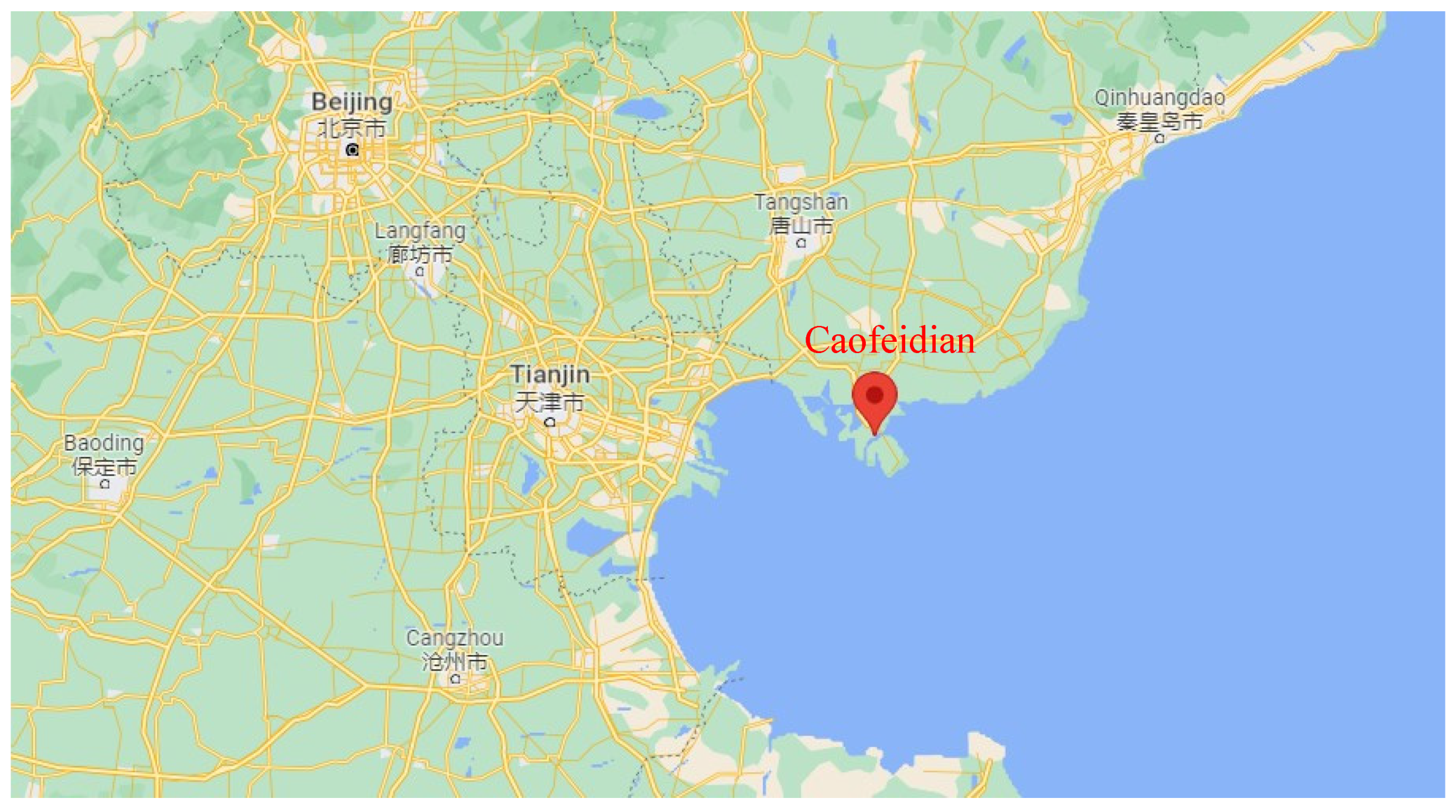
2.1. Caofeidian Dredger Fill
2.2. Solidifying Agents
2.2.1. Main Solidifying Agent
2.2.2. Additives
3. Unconfined Compression Test
3.1. Sample Preparation and Test Procedure
3.2. Test Results
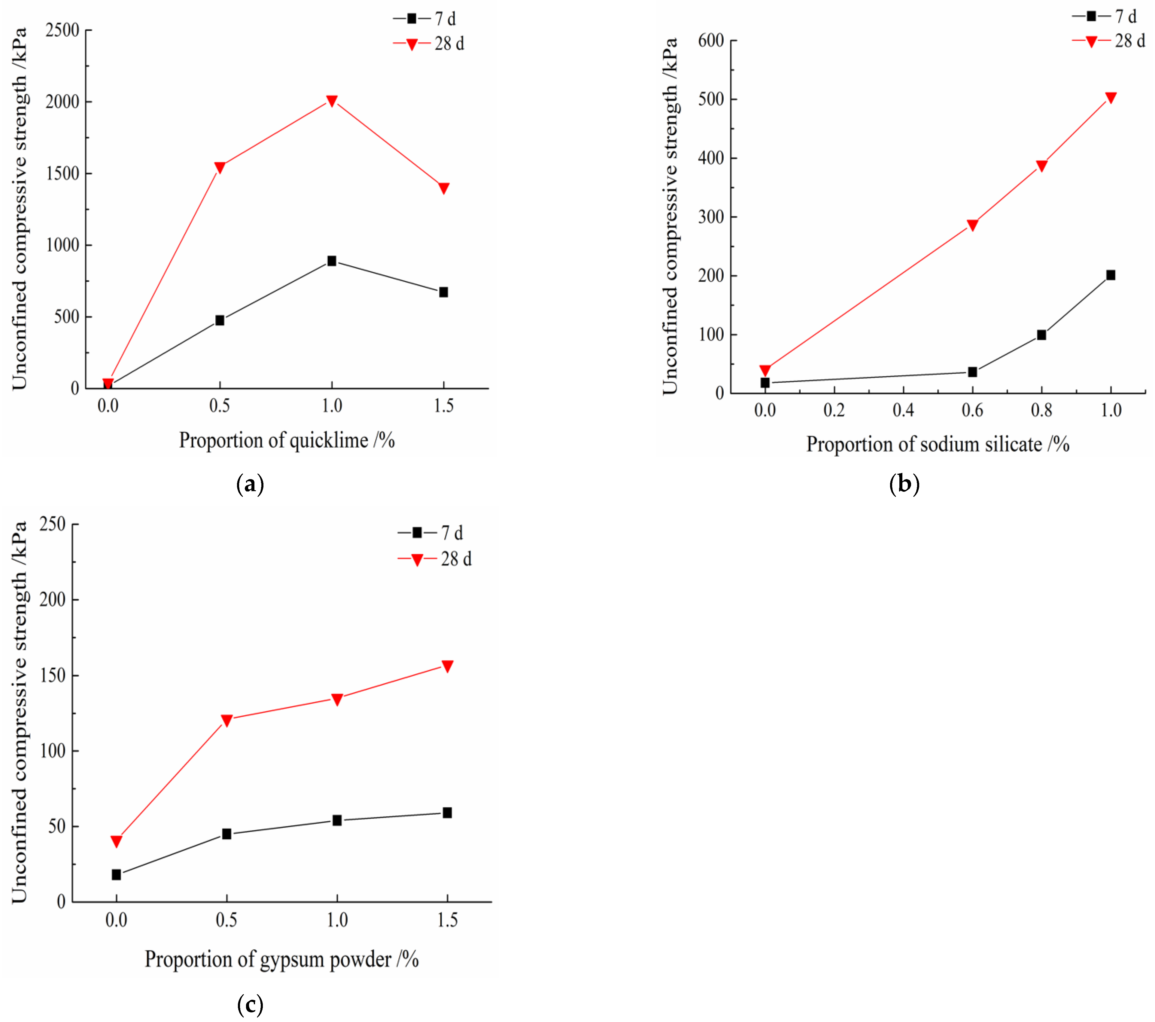
3.2.1. Single-Additive
3.2.2. Composite-Additive
4. Microanalysis
4.1. Sample Preparation and Test Procedures
4.2. Results and Analysis
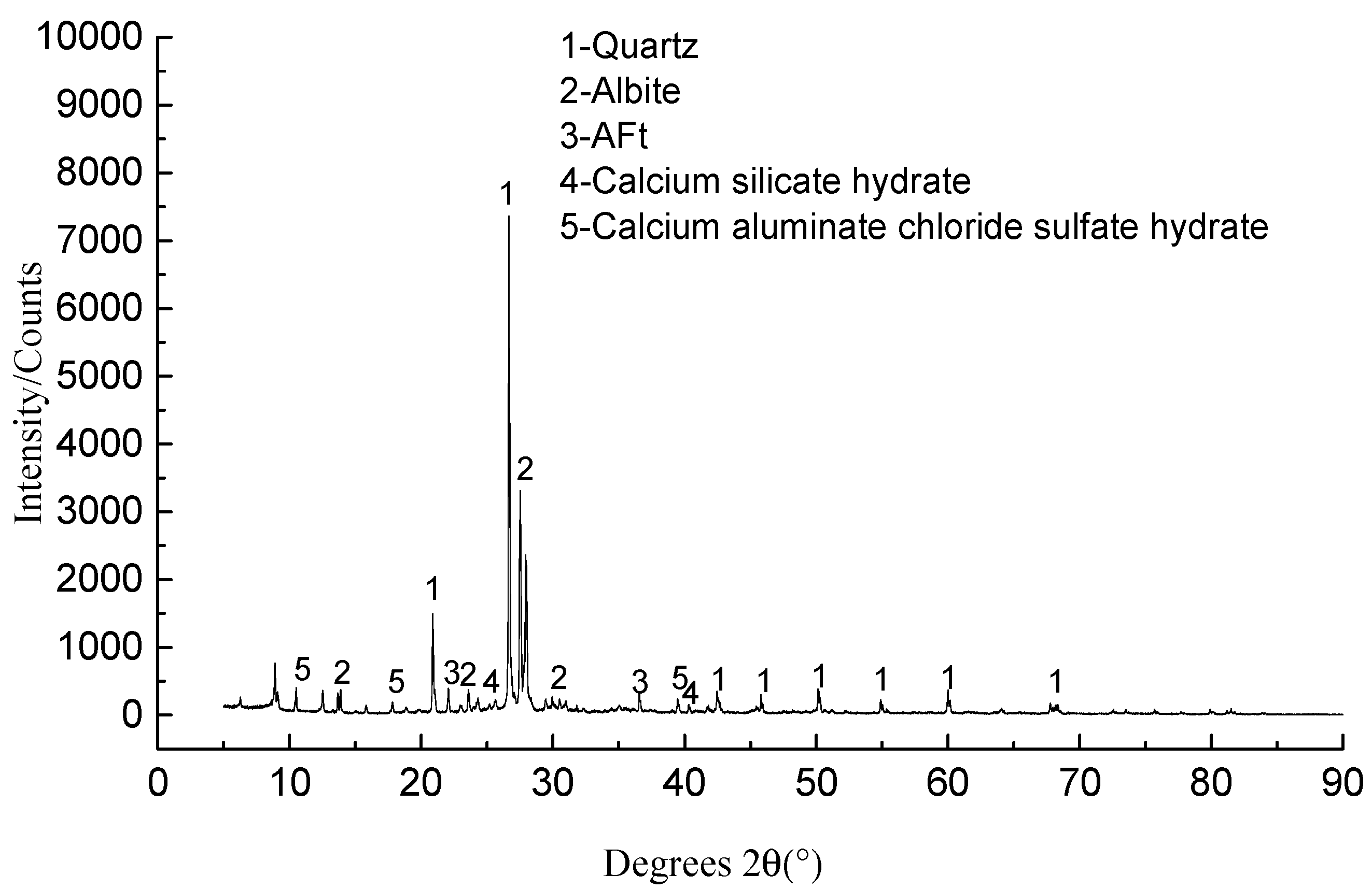
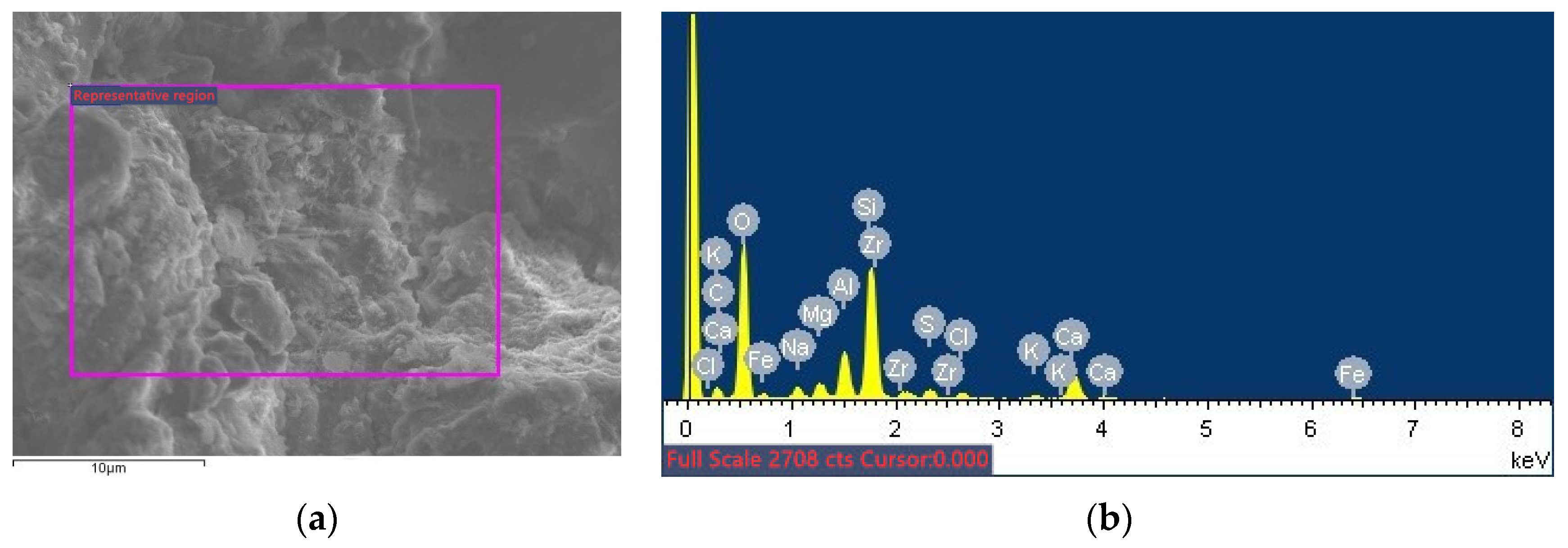
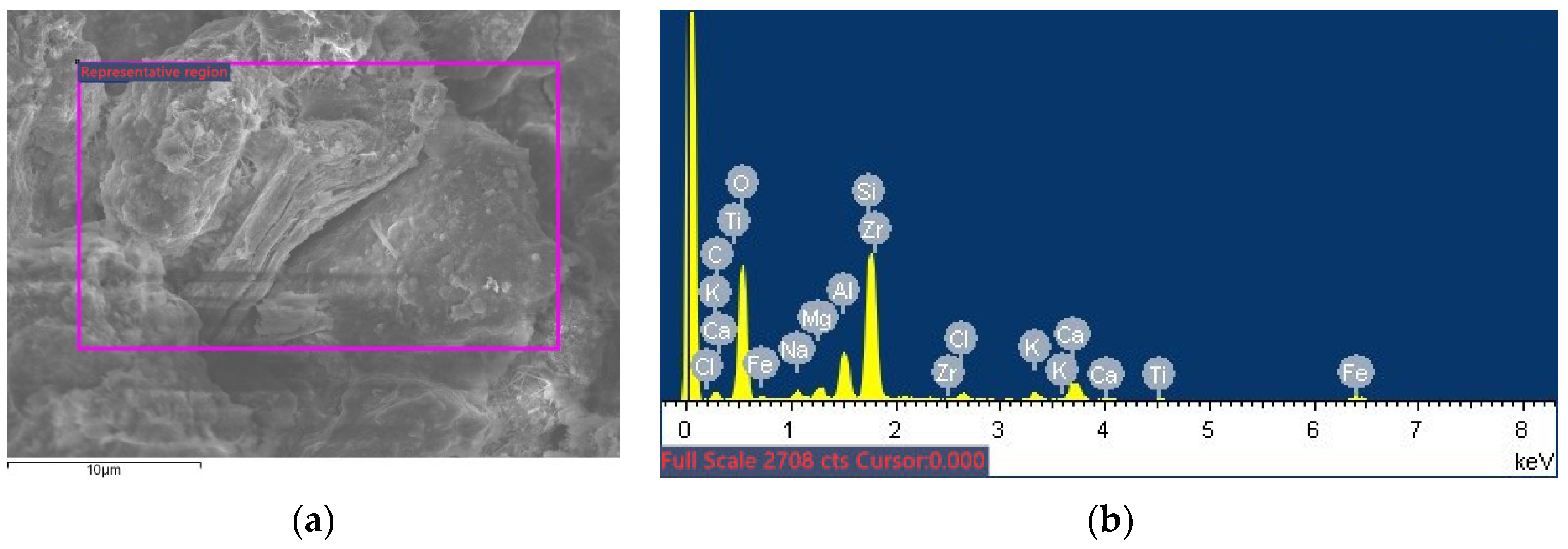
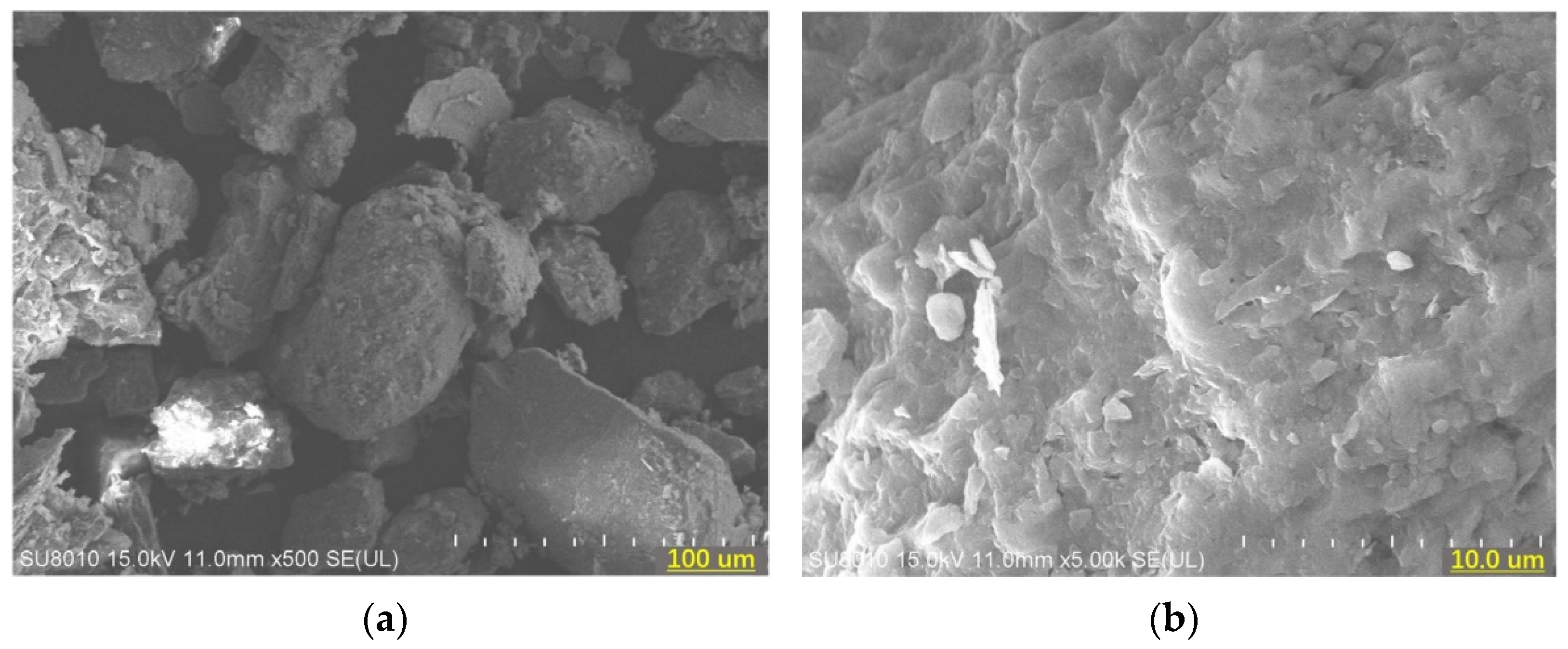
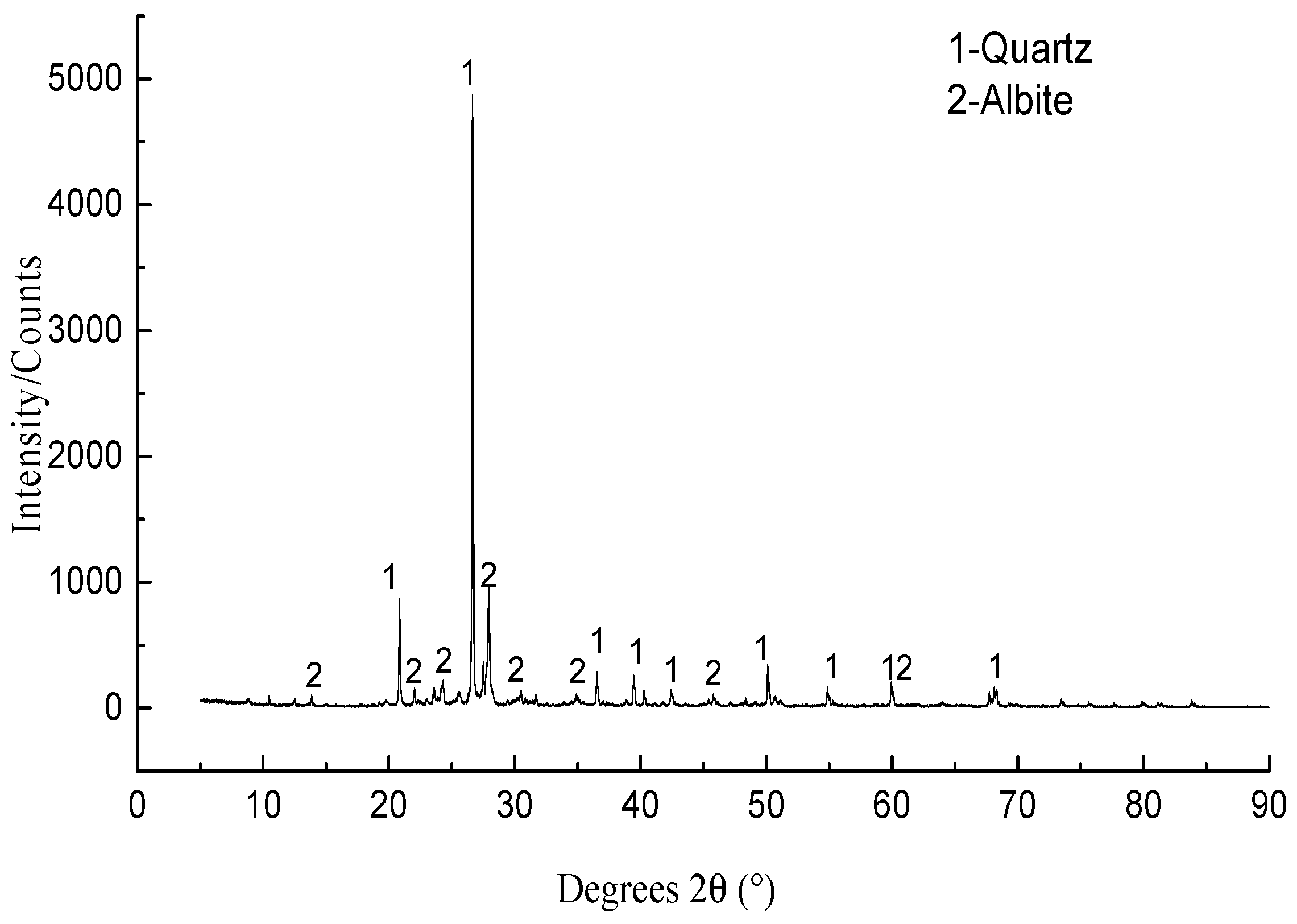
4.2.1. Unsolidified Soil
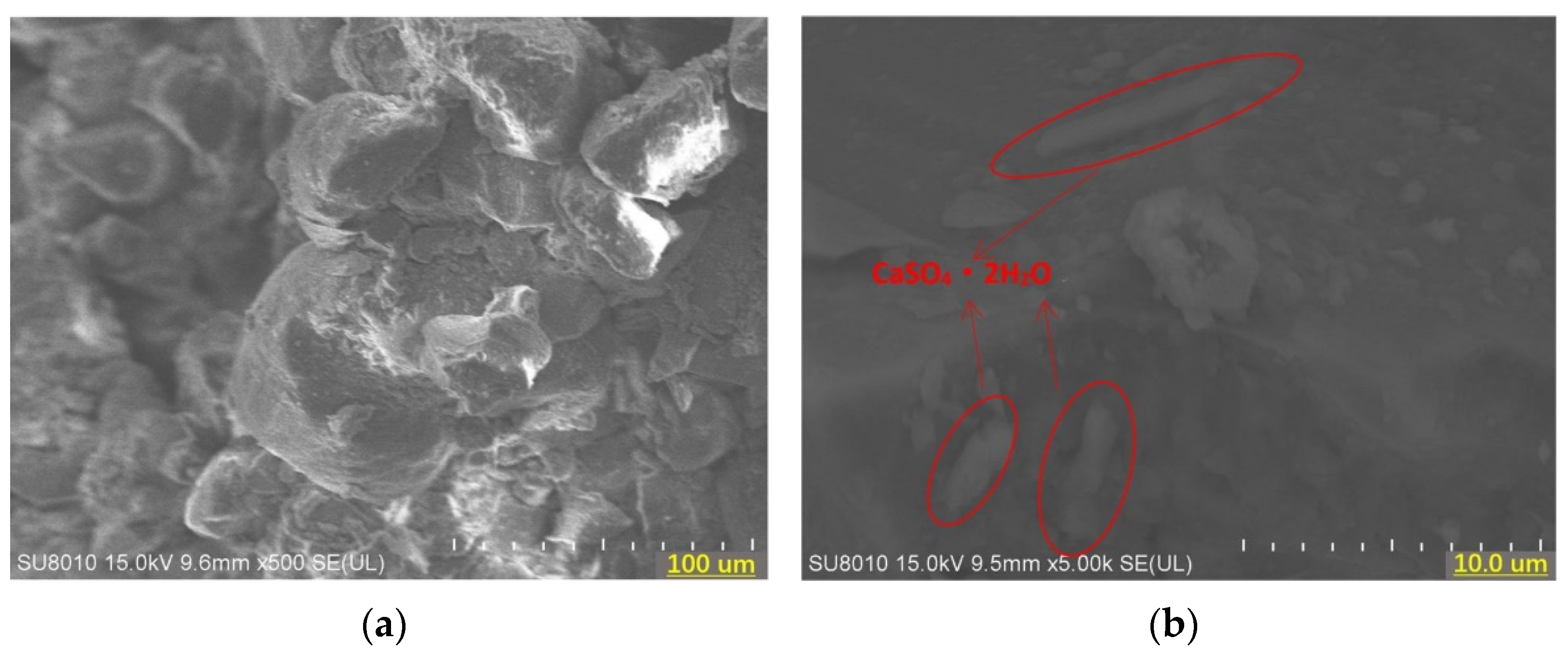
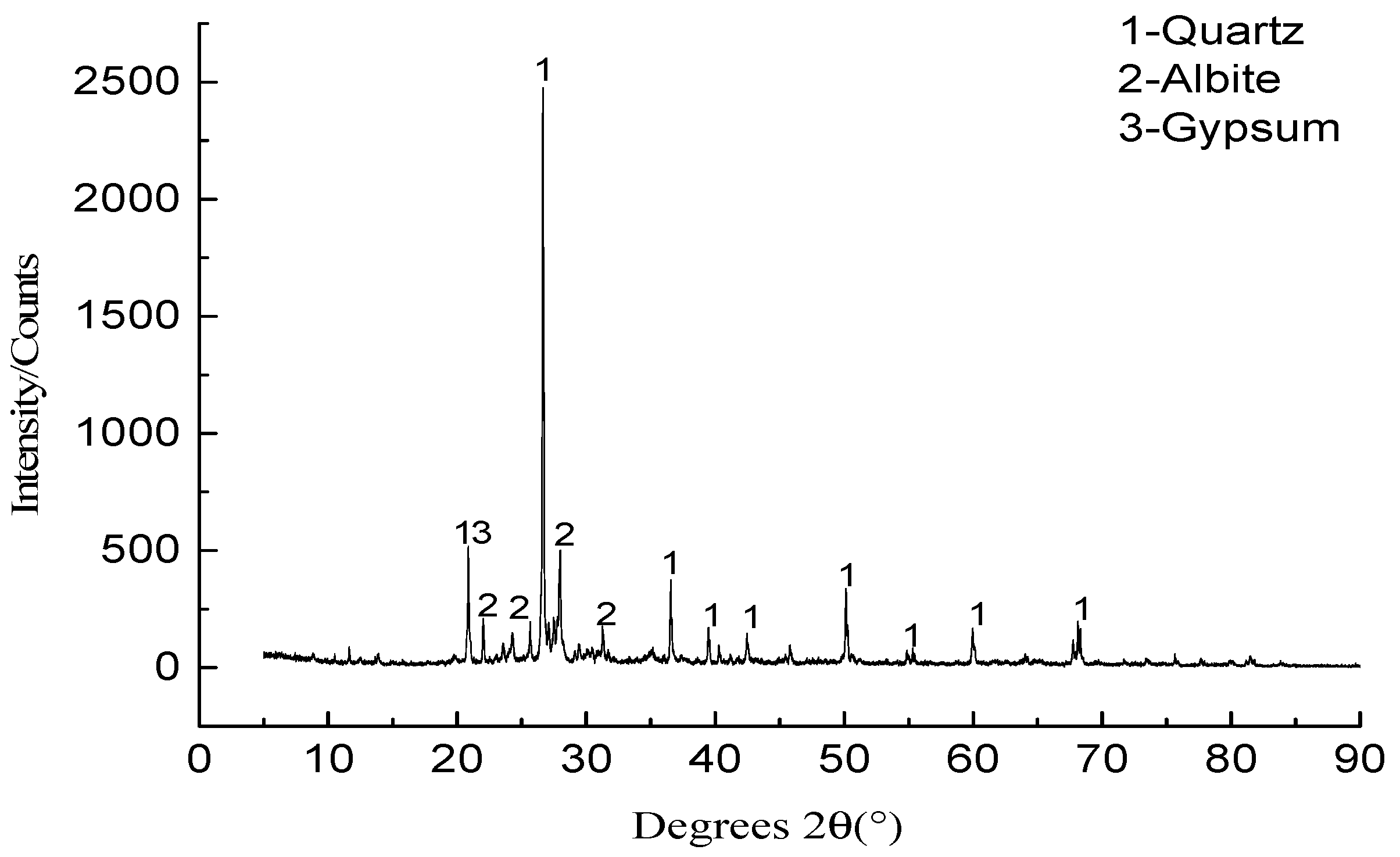
4.2.2. Solidified Soil with Slag and Gypsum Powder
4.2.3. Solidified Soil with Slag and Sodium Silicate
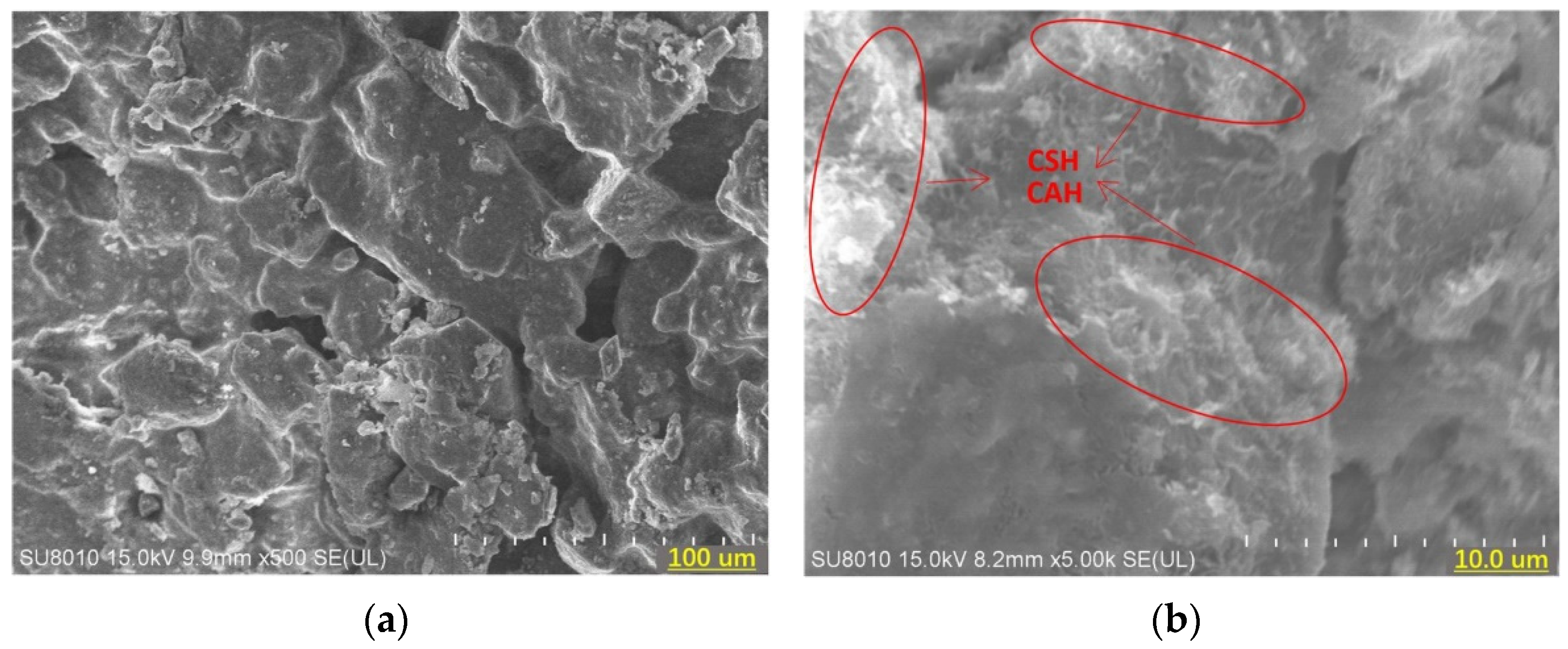
4.2.4. Solidified Soil with Slag and Quicklime
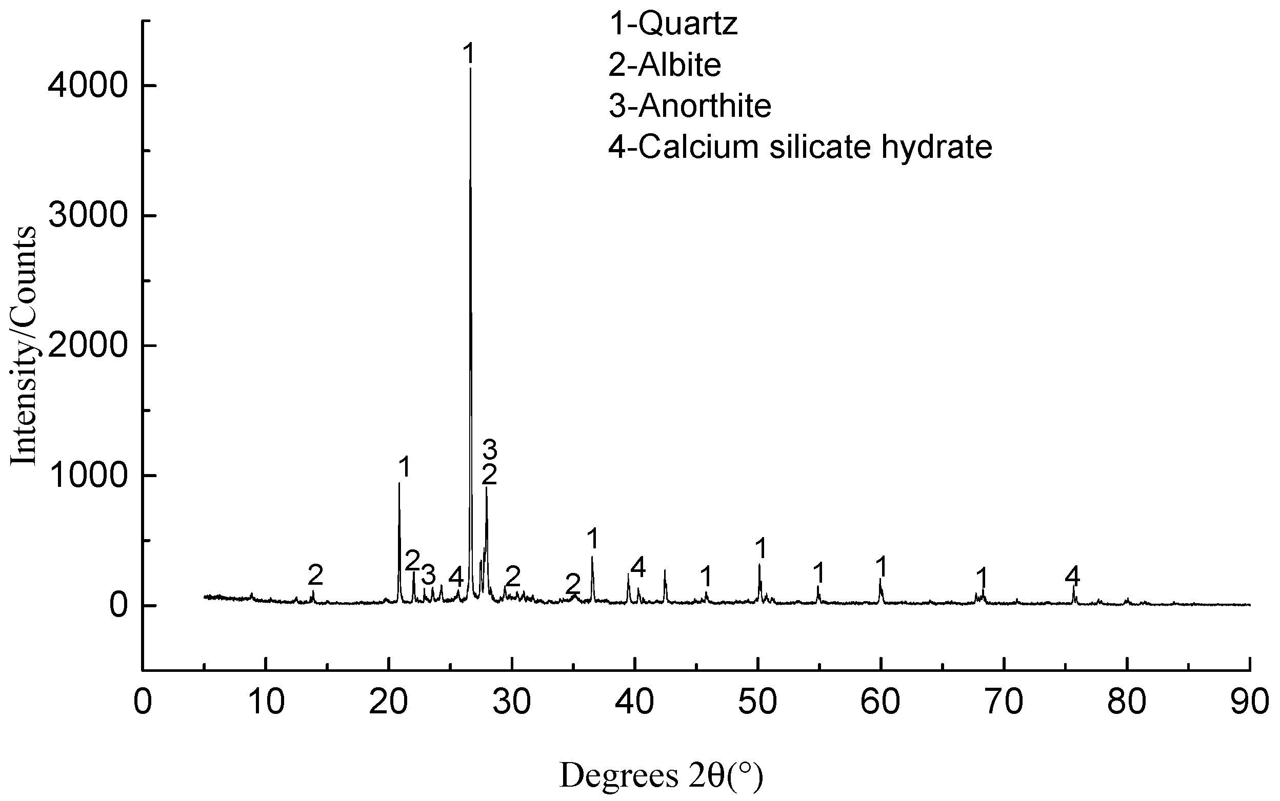
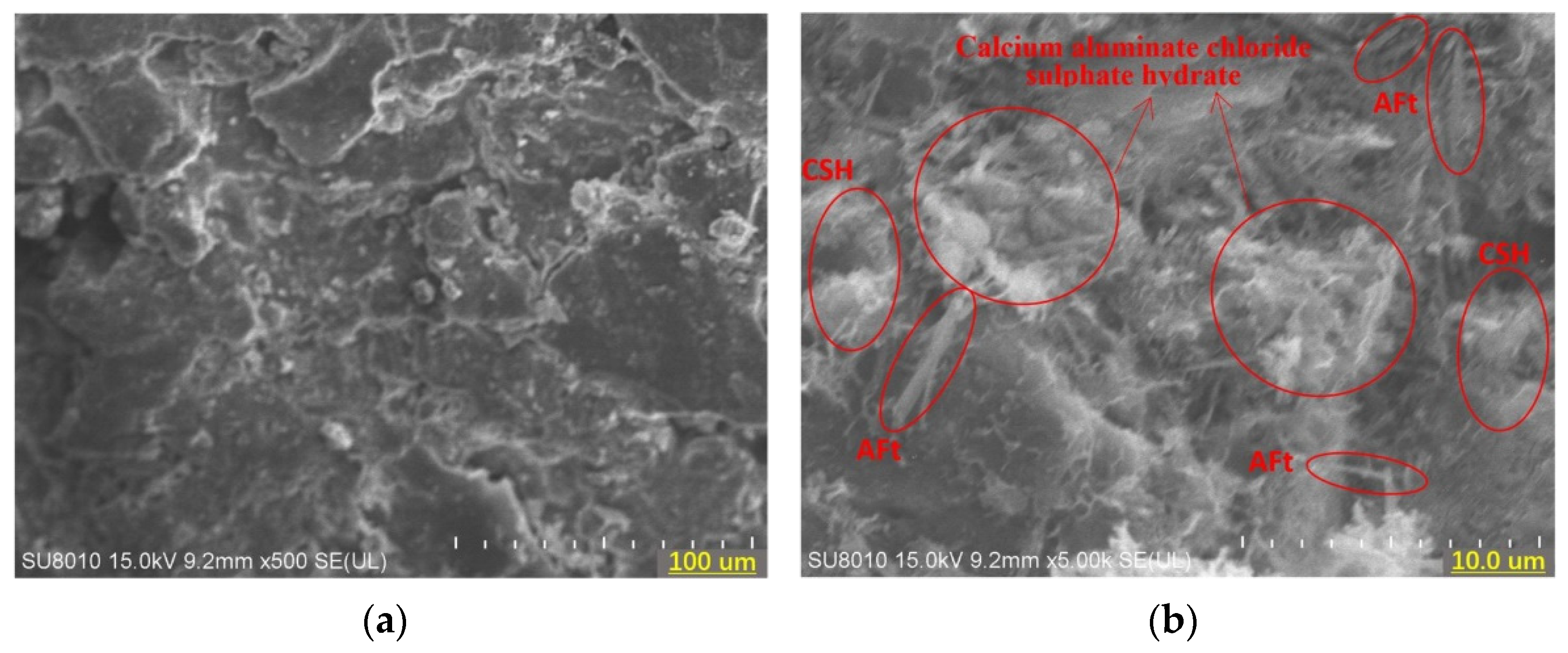
4.2.5. Solidified Soil with Slag and Composite Additives
5. Mechanism Analysis of Composite Slag Solidifying Agent
- CSH
- 2.
- AFt
- 3.
- Calcium aluminate chloride sulphate hydrate
6. Conclusions
- The composite slag solidifying agent can substantially improve the unconfined compressive strength of Caofeidian saline dredger fill. The additive quicklime contributes the most to this improvement. The optimal proportion is obtained as 10% slag + 1.0% quicklime + 0.8% sodium silicate + 1.5% gypsum powder.
- The microanalysis illustrates that a compact overall structure was obtained and few voids were observed in the solidified soil with the composite slag solidifying agent. This is an apparent improvement in the microstructure compared with that of unsolidified soil or solidified soil with slag and a single additive (quicklime, sodium silicate, or gypsum powder).
- The mechanism of composite slag solidifying agent for saline dredger fill is essentially the formation of CSH, AFt, and calcium aluminate chloride sulphate hydrate. First, the CSH colloid formed by slag hydrolysis improves the compactness of the soil. Second, AFt (formed by the combination of CAH and SO42−) can further strengthen the microstructure of the solidified soil. Finally, CAH can combine with SO42− and Cl− in the soil to form calcium aluminate chloride sulphate hydrate, which can effectively reduce the content of soluble salts in saline dredger fill and substantially improve the engineering characteristics of solidified soil.
Author Contributions
Funding
Institutional Review Board Statement
Informed Consent Statement
Data Availability Statement
Conflicts of Interest
Appendix A


| Element | C | O | Na | Mg | Al | Si | Cl | K | Ca | Fe | Zr |
|---|---|---|---|---|---|---|---|---|---|---|---|
| Mass percent (%) | 11.03 | 48.84 | 4.68 | 0.86 | 6.52 | 15.87 | 2.69 | 1.34 | 3.99 | 2.64 | 1.55 |
| Atomic percent (%) | 17.36 | 57.71 | 3.85 | 0.66 | 4.56 | 10.68 | 1.43 | 0.65 | 1.88 | 0.89 | 0.32 |
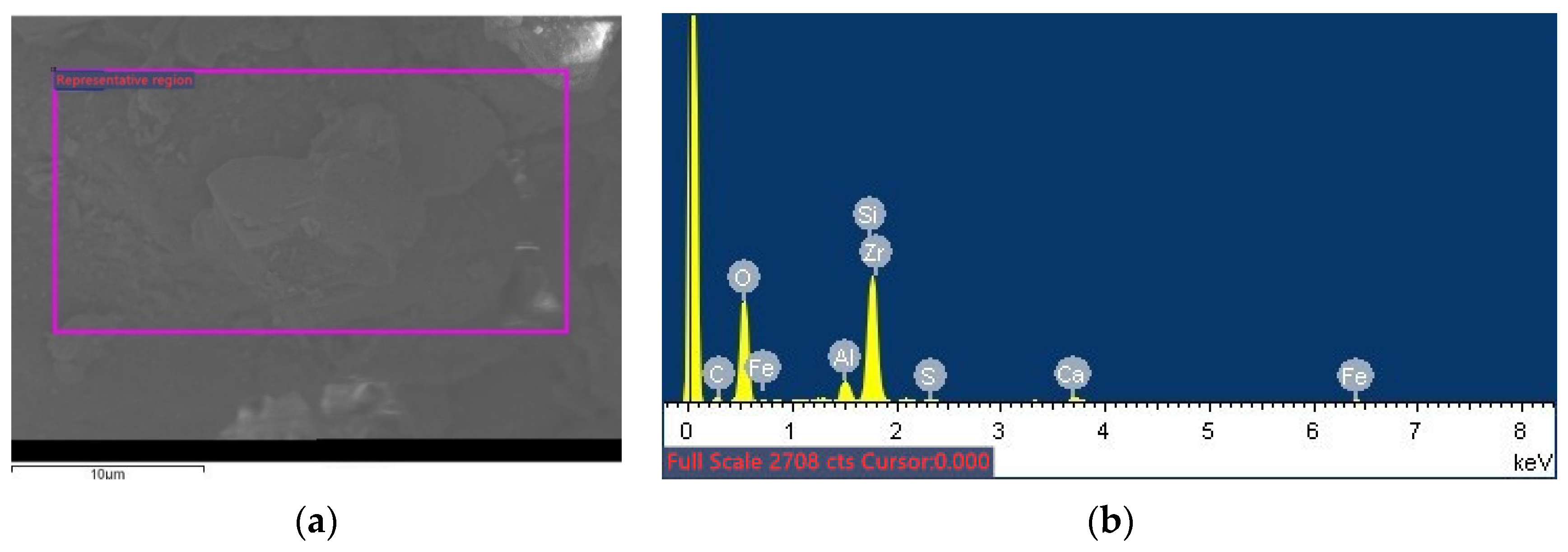
| Element | C | O | Al | Si | S | Ca | Fe | Zr |
|---|---|---|---|---|---|---|---|---|
| Mass percent (%) | 8.16 | 56.0 | 3.94 | 24.78 | 0.59 | 2.05 | 2.50 | 1.98 |
| Atomic percent (%) | 12.71 | 65.5 | 2.73 | 16.51 | 0.35 | 0.96 | 0.84 | 0.41 |
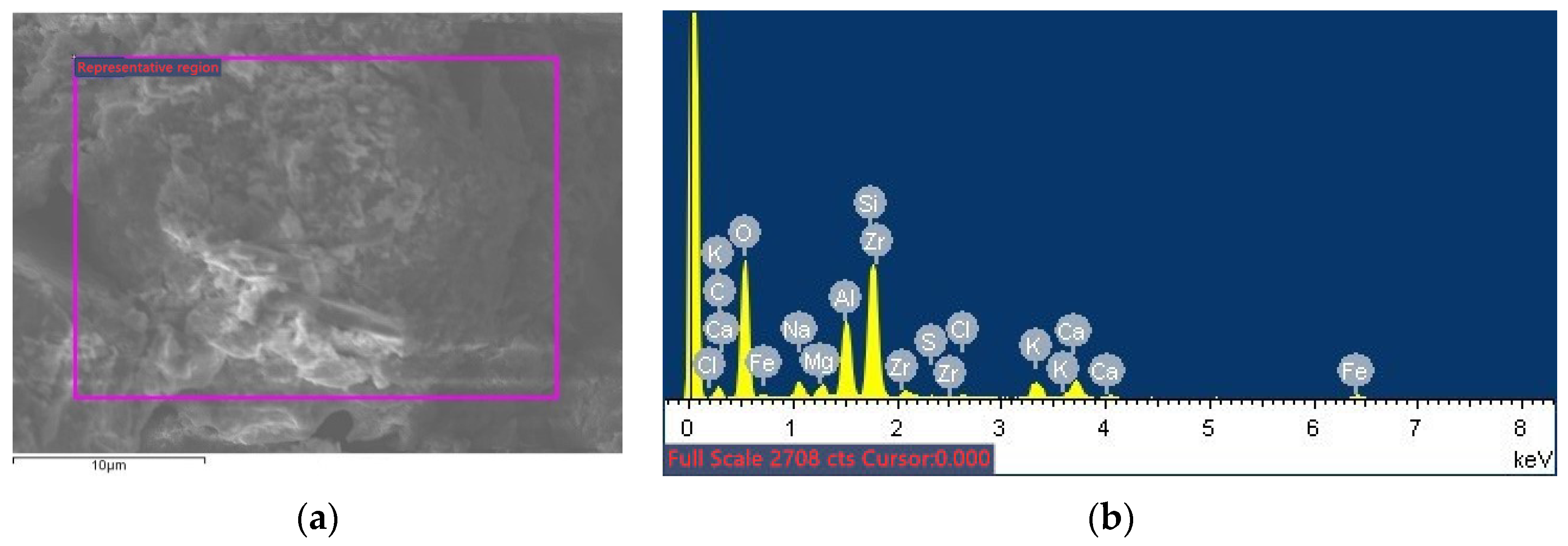
| Element | C | O | Na | Mg | Al | Si | S | Cl | K | Ca | Fe | Zr |
|---|---|---|---|---|---|---|---|---|---|---|---|---|
| Mass percent (%) | 13.97 | 48.18 | 1.95 | 1.21 | 7.27 | 14.99 | 0.32 | 0.50 | 3.21 | 3.98 | 2.36 | 2.05 |
| Atomic percent (%) | 21.61 | 55.94 | 1.58 | 0.93 | 5.00 | 9.91 | 0.18 | 0.26 | 1.53 | 1.85 | 0.78 | 0.42 |
| Element | C | O | Na | Mg | Al | Si | Cl | K | Ca | Fe | Zr |
|---|---|---|---|---|---|---|---|---|---|---|---|
| Mass percent (%) | 0.60 | 55.56 | 1.24 | 1.71 | 5.99 | 21.54 | 1.50 | 1.81 | 5.19 | 3.85 | 1.68 |
| Atomic percent (%) | 0.26 | 71.61 | 1.11 | 1.45 | 4.57 | 15.82 | 0.87 | 0.95 | 2.67 | 1.42 | 0.38 |

| Element | C | O | Na | Mg | Al | Si | S | Cl | K | Ca | Fe | Zr |
|---|---|---|---|---|---|---|---|---|---|---|---|---|
| Mass percent (%) | 15.25 | 52.01 | 1.37 | 1.52 | 4.26 | 14.13 | 1.34 | 0.80 | 0.90 | 5.12 | 1.71 | 1.59 |
| Atomic percent (%) | 22.81 | 58.40 | 1.07 | 1.12 | 2.83 | 9.04 | 0.75 | 0.41 | 0.41 | 2.29 | 0.55 | 0.31 |
References
- Zhang, T.; Xu, Y.; Wang, H. Application and Curing Mechanism of Soil Stabilizer. Adv. Mat. Res. 2012, 557–559, 809–812. [Google Scholar] [CrossRef]
- Elsharief, A.; Simoes, G.F. Effects of Lime on Permeability and Compressibility of Two Tropical Residual Soils. J. Environ. Eng. 2004, 130, 881–885. [Google Scholar]
- Elhagwa, A.; Richter, C.; Gedamu, A. Properties of New Reclaimed Soils in the Merowi Irrigation Project of North Sudan. J. Agric. Rural Dev. Trop. 2007, 108, 113–121. [Google Scholar]
- Youssef, N.A.R.; Maaitah, O.N.; Qdeshat, K. Soil Stabilization by Lime. Electron. J. Geotech. Eng. 2012, 17, 1747–1757. [Google Scholar]
- Rajasekaran, G.; Rao, S.N. Lime Migration Studies in Marine Clays. Ocean Eng. 1996, 23, 325–355. [Google Scholar] [CrossRef]
- Rajasekaran, G.; Rao, S.N. Permeability Characteristics of Lime Treated Marine Clay. Ocean Eng. 2002, 29, 113–127. [Google Scholar] [CrossRef]
- Rajasekaran, G.; Rao, S.N. Compressibility Behaviour of Lime-treated Marine Clay. Ocean Eng. 2002, 29, 545–559. [Google Scholar] [CrossRef]
- Rajasekaran, G. Sulphate Attack and Ettringite Formation in the Lime and Cement Stabilized Marine Clays. Ocean Eng. 2005, 32, 1133–1159. [Google Scholar] [CrossRef]
- McCarthy, M.J.; Csetenyi, L.J.; Sachdeva, A.; Dhir, R.K. Identifying the Role of Fly Ash Properties for Minimizing Sulfate-heave in Lime-stabilized Soils. Fuel 2012, 92, 27–36. [Google Scholar] [CrossRef]
- Miller, G.A.; Zaman, M. Field and Laboratory Evaluation of Cement Kiln Dust as a Soil Stabilizer. Transport. Res. Rec. 2000, 1714, 25–32. [Google Scholar] [CrossRef]
- Chan, C.M. Geo-parametric Study of Dredged Marine Clay with Solidification for Potential Reuse as Good Engineering Soil. Environ. Earth Sci. 2016, 75, 941. [Google Scholar] [CrossRef]
- Bell, F.G. An Assessment of Cement-PFA and Lime-PFA used to Stabilize Clay-size Materials. Bull. Int. Assoc. Eng. Geol. 1994, 49, 25–32. [Google Scholar] [CrossRef]
- Attom, M.F.; Al-Sharif, M.M. Soil Stabilization with Burned Olive Waste. Appl. Clay Sci. 1998, 13, 219–230. [Google Scholar] [CrossRef]
- Shihata, S.A.; Baghdadi, Z.A. Long-term Strength and Durability of Soil Cement. J. Mater. Civil. Eng. 2001, 13, 161–165. [Google Scholar] [CrossRef]
- Al-Amoudi, O.; Khan, K.; Al-Kahtani, N.S. Stabilization of a Saudi Calcareous Marl Soil. Constr. Build. Mater. 2010, 24, 1848–1854. [Google Scholar] [CrossRef]
- Wild, S.; Kinuthia, J.M.; Jones, G.I.; Higgins, D.D. Effects of Partial Substitution of Lime with Ground Granulated Blast Furnace Slag (GGBS) on the Strength Properties of Lime-stabilised Sulphate-bearing Clay Soils. Eng. Geol. 1998, 51, 37–53. [Google Scholar] [CrossRef]
- Hossain, K.; Mol, L. Some Engineering Properties of Stabilized Clayey Soils Incorporating Natural Pozzolans and Industrial Wastes. Constr. Build. Mater. 2011, 25, 3495–3501. [Google Scholar] [CrossRef]
- Kamon, M.; Gu, H.D. Improvement of Mechanical Properties of Ferrum Lime Stabilized Soil with the Addition of Aluminum Sludge. Mater. Sci. Res. Int. 2001, 7, 47–53. [Google Scholar] [CrossRef] [Green Version]
- Suryavanshi, A.K.; Scantlebury, J.D.; Lyon, S.B. Mechanism of Friedel’s Salt Formation in Cements rich in Tri-calcium Aluminate. Cem. Concr. Res. 1996, 26, 717–727. [Google Scholar] [CrossRef]
- Huang, X.; Li, Z.; Ning, J.; Xu, S. Principle and Method of Optimization Design for Soft Soil Stabilizer. J. Wuhan Univ. Technol.-Mat. Sci. Edit. 2009, 26, 154–160. [Google Scholar] [CrossRef]
- ASTM. ASTM D2487-17e1—Standard Practice for Classification of Soils for Engineering Purposes (Unified Soil Classification System); ASTM International: West Conshohocken, PA, USA, 2017. [Google Scholar]
- Liu, C.B. Study on Mechanism and Performance of the Coastal Saline Soil Cured by Slag Composite Curing Agent. Ph.D. Thesis, University of Science and Technology Beijing, Beijing, China, 2015. [Google Scholar]


| Material | Natural Moisture Content | Optimum Moisture Content | Maximum Dry Density | Gs | Liquid Limit | Plastic Limit | Plasticity Index | Liquid Index |
|---|---|---|---|---|---|---|---|---|
| (%) | (%) | (g/cm3) | (g/cm3) | (%) | (%) | N/A | N/A | |
| Caofeidian dredger fill | 26.1 | 16.4 | 1.64 | 2.70 | 26.29 | 13.6 | 12.69 | 0.88 |
| Anions | Cations | Total Soluble Salt | |||||||
|---|---|---|---|---|---|---|---|---|---|
| CO32− | HCO3− | SO42− | Cl− | Ca2+ | Mg2+ | K+ | Na+ | ||
| (mg/kg) | (mg/kg) | (mg/kg) | (mg/kg) | (mg/kg) | (mg/kg) | (mg/kg) | (mg/kg) | (mg/kg) | (%) |
| 0 | 304.9 | 1893.0 | 5972.9 | 297.4 | 3181.2 | 205.3 | 2288.5 | 13035.0 | 1.3 |
| Chemical Composition | SiO2 | Al2O3 | CaO | MgO | Others |
|---|---|---|---|---|---|
| Mass percentage (%) | 35–50 | 15–20 | 20–30 | 5–15 | Negligible |
| Number | Test Type | Slag (%) | Quicklime (%) | Sodium Silicate (%) | Gypsum Powder (%) |
|---|---|---|---|---|---|
| A0 | Single-additive | 0 | 0 | 0 | 0 |
| A1 | 10 | 0.5 (Level-1) | 0 | 0 | |
| A2 | 10 | 1.0 (L-2) | 0 | 0 | |
| A3 | 10 | 1.5 (L-3) | 0 | 0 | |
| A4 | 10 | 0 | 0.6 (L-1) | 0 | |
| A5 | 10 | 0 | 0.8 (L-2) | 0 | |
| A6 | 10 | 0 | 1.0 (L-3) | 0 | |
| A7 | 10 | 0 | 0 | 0.5 (L-1) | |
| A8 | 10 | 0 | 0 | 1.0 (L-2) | |
| A9 | 10 | 0 | 0 | 1.5 (L-3) | |
| A10 | Composite-additive | 10 | 0.5 (L-1) | 0.6 (L-1) | 0.5 (L-1) |
| A11 | 10 | 0.5 | 0.8 (L-2) | 1.0 (L-2) | |
| A12 | 10 | 0.5 | 1.0 (L-3) | 1.5 (L-3) | |
| A13 | 10 | 1.0 (L-2) | 0.6 | 1.0 | |
| A14 | 10 | 1.0 | 0.8 | 1.5 | |
| A15 | 10 | 1.0 | 1.0 | 0.5 | |
| A16 | 10 | 1.5 (L-3) | 0.6 | 1.5 | |
| A17 | 10 | 1.5 | 0.8 | 0.5 | |
| A18 | 10 | 1.5 | 1.0 | 1.0 |
| Number | Unconfined Compressive Strength (kPa) | |
|---|---|---|
| 7 d | 28 d | |
| A0 | 18 | 41 |
| A1 | 475 | 1550 |
| A2 | 890 | 2015 |
| A3 | 672 | 1406 |
| A4 | 36 | 288 |
| A5 | 99 | 389 |
| A6 | 201 | 505 |
| A7 | 45 | 121 |
| A8 | 54 | 135 |
| A9 | 59 | 157 |
| Number | Unconfined Compressive Strength (kPa) | |
|---|---|---|
| 7 d | 28 d | |
| A10 | 1483 | 2764 |
| A11 | 1981 | 3033 |
| A12 | 1681 | 2870 |
| A13 | 1886 | 3200 |
| A14 | 2007 | 3370 |
| A15 | 1907 | 3020 |
| A16 | 1827 | 2401 |
| A17 | 1680 | 2640 |
| A18 | 1460 | 2374 |
| T | 7d | 28d | ||||
|---|---|---|---|---|---|---|
| Quicklime | Sodium Silicate | Gypsum Powder | Quicklime | Sodium Silicate | Gypsum Powder | |
| T1 | 5145 | 5200 | 5070 | 8667 | 8365 | 8424 |
| T2 | 5800 | 5668 | 5327 | 9590 | 9043 | 8607 |
| T3 | 4967 | 5048 | 5515 | 7415 | 8264 | 8641 |
| t1 | 1715 | 1733 | 1690 | 2889 | 2788 | 2808 |
| t2 | 1933 | 1889 | 1776 | 3197 | 3014 | 2869 |
| t3 | 1656 | 1683 | 1838 | 2472 | 2755 | 2880 |
| Range | 277 | 206 | 148 | 725 | 259 | 72 |
| Optimal proportion | 1.0% | 0.8% | 1.5% | 1.0% | 0.8% | 1.5% |
| influence factor | Quicklime > Sodium silicate > Gypsum powder | Quicklime > Sodium silicate > Gypsum powder | ||||
| Number | Description | Proportion of Solidifying Agent/% | |||
|---|---|---|---|---|---|
| Slag (%) | Gypsum Powder (%) | Sodium Silicate (%) | Quicklime (%) | ||
| B1 | Unsolidified soil | 0 | 0 | 0 | 0 |
| B2 | Slag + Gypsum powder | 10 | 1.5 | 0 | 0 |
| B3 | Slag + Sodium silicate | 10 | 0 | 0.8 | 0 |
| B4 | Slag + quicklime | 10 | 0 | 0 | 1 |
| B5 | Slag + all | 10 | 1.5 | 0.8 | 1 |
Publisher’s Note: MDPI stays neutral with regard to jurisdictional claims in published maps and institutional affiliations. |
© 2022 by the authors. Licensee MDPI, Basel, Switzerland. This article is an open access article distributed under the terms and conditions of the Creative Commons Attribution (CC BY) license (https://creativecommons.org/licenses/by/4.0/).
Share and Cite
Shen, Y.; Li, P.; Jing, P.; Liu, Y.; Feng, R.; Liu, X. Experiment and Mechanism Analysis on the Solidification of Saline Dredger Fill with Composite Slag Solidifying Agent: A Case Study in Caofeidian, China. Appl. Sci. 2022, 12, 1849. https://doi.org/10.3390/app12041849
Shen Y, Li P, Jing P, Liu Y, Feng R, Liu X. Experiment and Mechanism Analysis on the Solidification of Saline Dredger Fill with Composite Slag Solidifying Agent: A Case Study in Caofeidian, China. Applied Sciences. 2022; 12(4):1849. https://doi.org/10.3390/app12041849
Chicago/Turabian StyleShen, Yupeng, Ping Li, Peng Jing, Ying Liu, Ruiling Feng, and Xin Liu. 2022. "Experiment and Mechanism Analysis on the Solidification of Saline Dredger Fill with Composite Slag Solidifying Agent: A Case Study in Caofeidian, China" Applied Sciences 12, no. 4: 1849. https://doi.org/10.3390/app12041849
APA StyleShen, Y., Li, P., Jing, P., Liu, Y., Feng, R., & Liu, X. (2022). Experiment and Mechanism Analysis on the Solidification of Saline Dredger Fill with Composite Slag Solidifying Agent: A Case Study in Caofeidian, China. Applied Sciences, 12(4), 1849. https://doi.org/10.3390/app12041849