
Anti-Collision System for Small Civil Aircraft


Abstract
:1. Introduction
2. Anti-Collision Systems
2.1. Sense and Avoid Systems and Their Use in Small Civil Aircraft
2.2. Selected Published Research Results in the Field of Anti-Collision Systems
3. Design of the Anti-Collision System for the Category of Small Aircraft
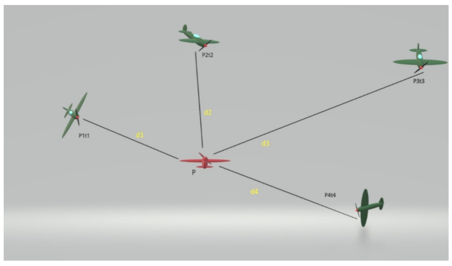
Model of Anti-Collision System
4. Accuracy of Determining the Position of Flying Objects by Anti-Collision System
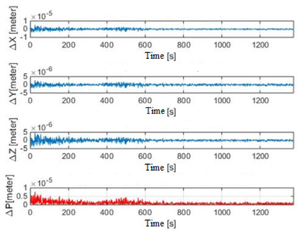
4.1. Verification of the Functionality of Derived Algorithms


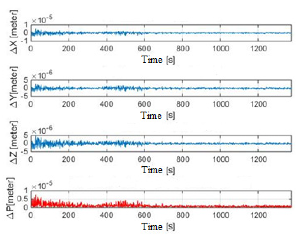
4.2. Methodological Error of the Anti-Collision System


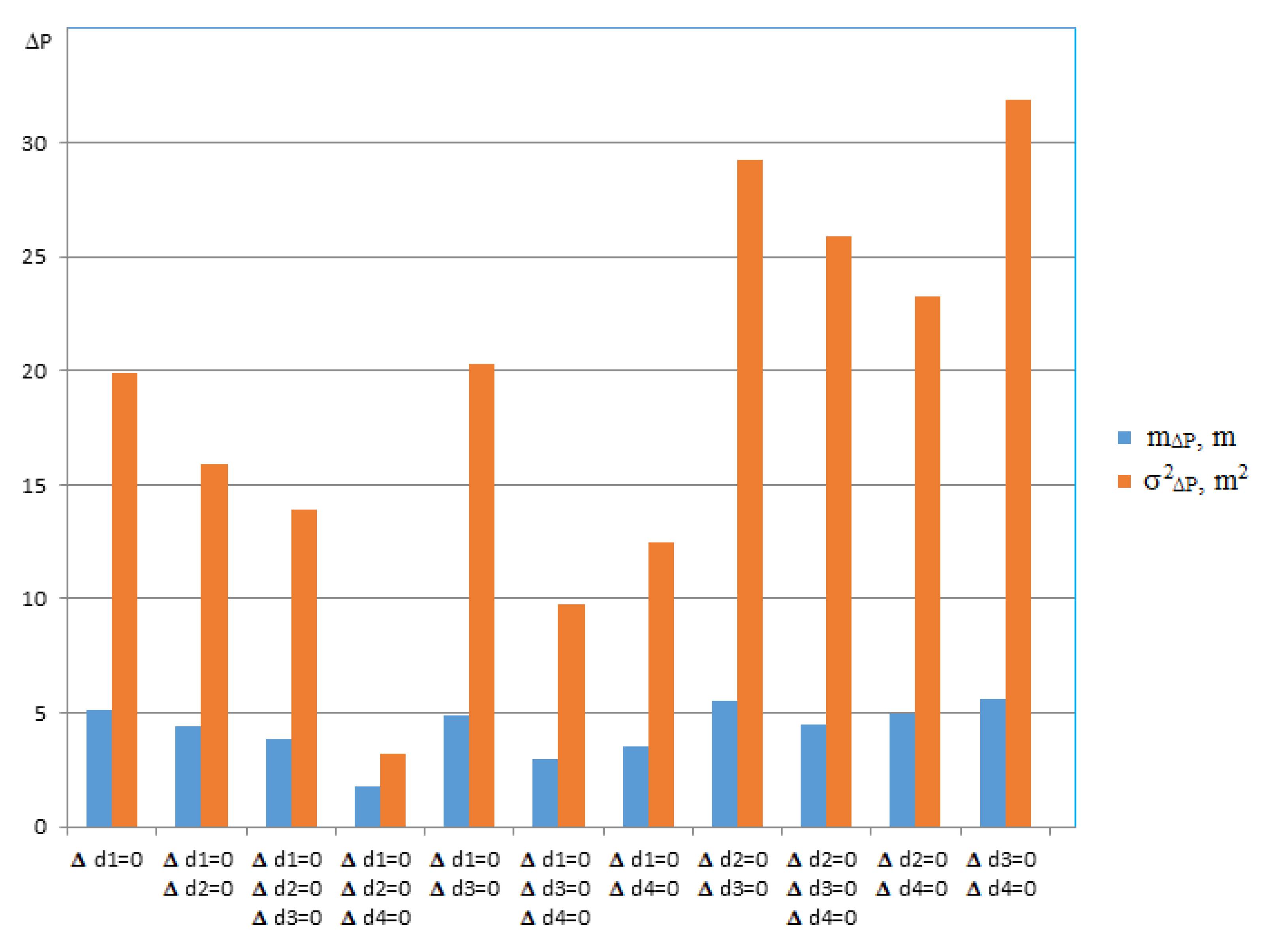
4.3. Methodology for Evaluating the Accuracy of the Anti-Collision System
4.4. Discussion and Results of Anti-Collision System Accuracy Evaluation

5. Conclusions
Author Contributions
Funding
Institutional Review Board Statement
Informed Consent Statement
Data Availability Statement
Acknowledgments
Conflicts of Interest
References
- Džunda, M.; Dzurovcin, P.; Kavka, P. Utilizing the principle of relative navigation in anti-collision systems. In Proceedings of the International Scientific Conference on Modern Safety Technologies in Transportation (MOSATT), Kosice, Slovakia, 28–29 November 2019; pp. 39–44. [Google Scholar]
- Džunda, M.; Dzurovčin, P.; Koščák, P.; Liptáková, D. Relative navigation in anti-collision systems for UAV. In Proceedings of the International Scientific Conference on Modern Safety Technologies in Transportation (MOSATT), Kosice, Slovakia, 28–29 November 2019; pp. 44–48. [Google Scholar]
- Džunda, M.; Dzurovcin, P.; Cekanova, D. Operational economic aspects of warning collision systems for helicopters. In Proceedings of the 22nd International Scientific Conference on Transport Means, Trakai, Lithuania, 3–5 October 2018; pp. 1151–1155, PTS I–III. [Google Scholar]
- Beinarovica, A.; Gorobetz, M.; Levchenkov, A. Control algorithm of multiple unmanned electrical aerial vehicles for their collision prevention. In Proceedings of the 12th International Conference on Intelligent Technologies in Logistics and Mechatronics Systems (ITELMS), Panevezys, Lithuania, 26–27 April 2018; pp. 37–43. [Google Scholar]
- Graffstein, J. Functioning of an air anti-collision system during the test flight. Aviation 2014, 18, 44–51. [Google Scholar] [CrossRef]
- Wang, Z.; Yu, B.; Chen, J.; Liu, C.; Zhan, K.; Sui, X.; Xue, Y.; Li, J. Research on lidar point cloud segmentation and collision detection algorithm. In Proceedings of the 6th International Conference on Information Science and Control Engineering (ICISCE), Shanghai, China, 20–22 December 2019; pp. 475–479. [Google Scholar] [CrossRef]
- Lee, R.C.; Chen, B.H. Building an UAV anti-collision system with low-power FM ranging radar and camera image. In Proceedings of the 2019 IEEE Eurasia Conference on IOT, Communication and Engineering (ECICE), Yunlin, Taiwan, 3–6 October 2019; pp. 387–389. [Google Scholar] [CrossRef]
- Bascetta, L.; Magnani, G.; Rocco, P.; Migliorini, R.; Pelagatti, M. Anti-collision systems for robotic applications based on laser time-of-flight sensors. In Proceedings of the IEEE/ASME, International Conference on Advanced Intelligent Mechatronics, Montreal, QC, Canada, 6–9 July 2010; pp. 278–284. [Google Scholar] [CrossRef] [Green Version]
- Lee, H.W.; Zhu, Y.; Shi, X.; Peng, F.F.; Jin, W.J. Research of four-axis aircraft using WIFI and rotary anti-collision system. In Proceedings of the 2018 IEEE International Conference on Applied System Invention (ICASI), Tokyo, Japan, 13–17 April 2018; pp. 665–668. [Google Scholar] [CrossRef]
- Zanobini, A. A drone anti-collision system: Maintaining a fixed distance from a target during the flight. In Proceedings of the 2016 18th Mediterranean Electrotechnical Conference (MELECON), Limassol, Cyprus, 16–20 April 2016; pp. 1–6. [Google Scholar] [CrossRef]
- Brcko, T.; Androjna, A.; Srše, J.; Boć, R. Vessel multi-parametric collision avoidance decision model: Fuzzy approach. J. Mar. Sci. Eng. 2021, 9, 49. [Google Scholar] [CrossRef]
- Fu, H.; Cui, B.; Zhuang, B.; Zhang, J. Anti-collision and obstacle avoidance of mobile sensor-plus-actuator networks over distributed parameter systems with time-varying delay. Int. J. Control Autom. Syst. 2021, 19, 2373–2384. [Google Scholar] [CrossRef]
- Tarazona, R.D.F.; Lopera, F.R.; Sánchez, G.D.G. Anti-collision system for indoors quadcopter navigation using fuzzy controllers and range sensors. Rev. Investig. Univ. Quindio 2016, 28, 101–108. [Google Scholar]
- Tarazona, R.D.F.; Lopera, F.R.; Sánchez, G.D.G. Anti-collision system for navigation inside an UAV using fuzzy controllers and range sensors. In Proceedings of the XIX Symposium on Image, Signal Processing and Artificial Vision (STSIVA), Armenia, Colombia, 17–19 September 2014. [Google Scholar]
- Gorobetz, M.; Ribickis, L.; Levchenkov, A.; Beinarovica, A. Machine learning algorithm of immune neuro-fuzzy anti-collision embedded system for autonomous unmanned aerial vehicles team. In Proceedings of the 2nd International Conference on Applications of Intelligent Systems (APPIS), Las Palmas de Gran Canaria, Spain, 7–9 January 2019. [Google Scholar]
- Beinarovica, A.; Gorobetz, M.; Levchenkov, A. Self-organized learning algorithm for immune neuro-fuzzy anti-collision system of autonomous unmanned aerial vehicles’ team. In Proceedings of the 22nd International Scientific Conference on Transport Means (Transport Means), Trakai, Lithuania, 3–5 October 2018; pp. 1334–1341. [Google Scholar]
- Liu, Y.; Liang, Y.; Li, K. Anti-collision cooperative control strategy for multi-agent based on collision probability. Proceedings of the 4th International-Academy-of-Astronautics Conference on Dynamics and Control of Space Systems (DyCoSS ’2018), National University of Defense Technology, Changsha, China, 21–23 May 2018; Book Series: Advances in the Astronautical Sciences. 2018, Volume 165, pp. 199–207. Available online: https://www.univelt.com/linkedfiles/v165%20Contents.pdf (accessed on 20 January 2022).
- Visual Scanning Technique. Available online: https://skybrary.aero/articles/visual-scanning-technique (accessed on 1 January 2022).
- Improved Ground Collision Avoidance System (DRC-TOPS-19). Available online: https://technology.nasa.gov/patent/DRC-TOPS-19 (accessed on 1 January 2022).
- Vosecký, S. Radionavigace. Učební Texty pro Teoretickou Přípravu Dopravních Pilotů dle Předpisu JAR-FCL-1; CERM: Brno, Slovakia, 2011; ISBN 9788072047642. [Google Scholar]
- Džunda, M.; Kotianová, N.; Dzurovčin, P.; Szabo, S.; Jenčová, E.; Vajdová, I.; Koščák, P.; Liptáková, D.; Hanák, P. Selected aspects of using the telemetry method in synthesis of RelNav system for air traffic control. Int. J. Environ. Res. Public Health 2020, 17, 213. [Google Scholar] [CrossRef] [PubMed] [Green Version]
- Džunda, M. Modeling of the flight trajectory of flying objects. In Proceedings of the NTAD 2018—13th International Scientific Conference—New Trends in Aviation Development, Kosice, Slovakia, 30–31 August 2018; pp. 132–136. [Google Scholar]
- El Marady, A.A.W. Enhancing accuracy and security of ADS-B via MLAT assisted-flight information system. In Proceedings of the 2017 12th International Conference on Computer Engineering and Systems (ICCES), Cairo, Egypt, 19–20 December 2017; pp. 182–187. [Google Scholar] [CrossRef]


| S.n. | Identification | Lat. (° sš) | Long. (°vd) | Lat. (Rad) | Long. (Rad) | Height ASL (m) |
|---|---|---|---|---|---|---|
| 1. | RJA39K | 48,720 | 20,869 | 0.850324 | 0.364233 | 11,262 |
| 2. | FHM6112 | 48,758 | 21,119 | 0.850988 | 0.368596 | 10,683 |
| 3. | LOT653 | 48,633 | 21,289 | 0.848806 | 0.371563 | 7003 |
| 4. | WZZ3007 | 48,916 | 21,442 | 0.853745 | 0.374233 | 10,363 |
| 5. | LOT5MF | 48,771 | 21,148 | 0.851215 | 0.369102 | 3784 |
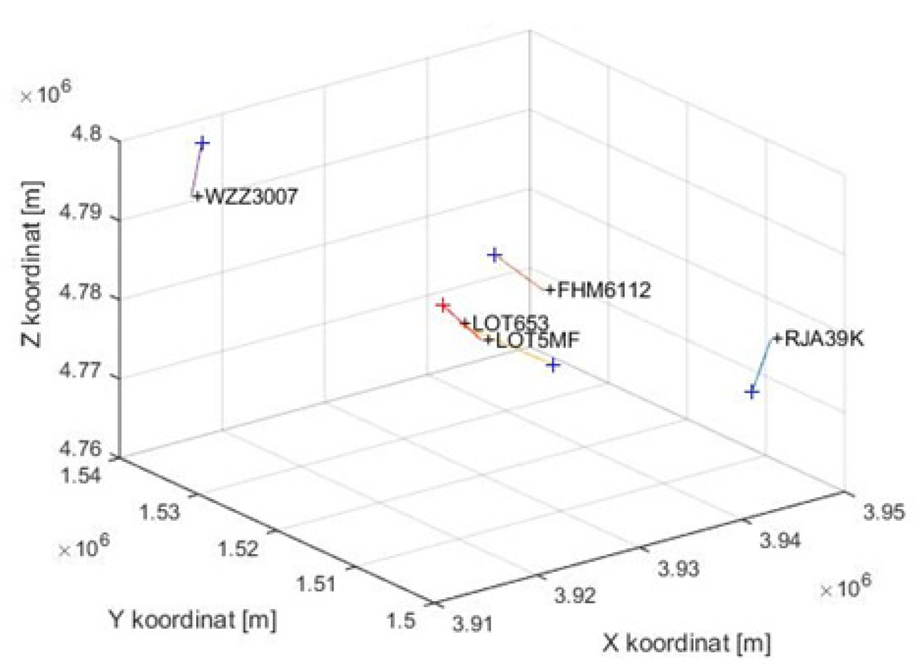
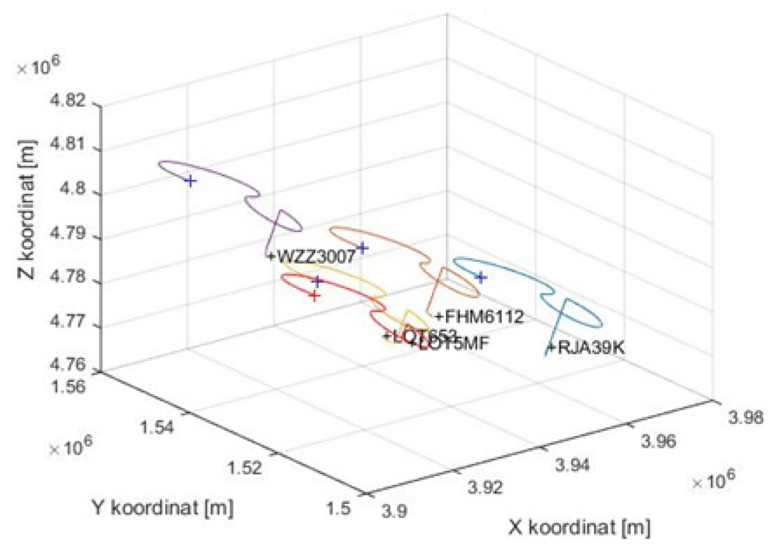
| S.n. | Identification | X (km) | Y (km) | Z (km) |
|---|---|---|---|---|
| 1 | RJA39K | 3946.254 | 1504.482 | 4778.536 |
| 2 | FHM6112 | 3936.328 | 1520.402 | 4780.893 |
| 3 | LOT653 | 3939.279 | 1534.99 | 4768.94 |
| 4 | WZZ3007 | 3915.165 | 1537.648 | 4792.236 |
| 5 | LOT5MF | 3930.301 | 1520.361 | 4776.659 |
| ID | X (km) | Y (km) | Z (km) | Lat. (°) | Long. (°) | Height ASL (m) |
|---|---|---|---|---|---|---|
| LOT5MF | 3930.301 | 1520.361 | 4776.659 | 48.7712N | 21.1476E | 3784 |
Publisher’s Note: MDPI stays neutral with regard to jurisdictional claims in published maps and institutional affiliations. |
© 2022 by the authors. Licensee MDPI, Basel, Switzerland. This article is an open access article distributed under the terms and conditions of the Creative Commons Attribution (CC BY) license (https://creativecommons.org/licenses/by/4.0/).
Share and Cite
Džunda, M.; Dzurovčin, P.; Melníková, L. Anti-Collision System for Small Civil Aircraft. Appl. Sci. 2022, 12, 1648. https://doi.org/10.3390/app12031648
Džunda M, Dzurovčin P, Melníková L. Anti-Collision System for Small Civil Aircraft. Applied Sciences. 2022; 12(3):1648. https://doi.org/10.3390/app12031648
Chicago/Turabian StyleDžunda, Milan, Peter Dzurovčin, and Lucia Melníková. 2022. "Anti-Collision System for Small Civil Aircraft" Applied Sciences 12, no. 3: 1648. https://doi.org/10.3390/app12031648
APA StyleDžunda, M., Dzurovčin, P., & Melníková, L. (2022). Anti-Collision System for Small Civil Aircraft. Applied Sciences, 12(3), 1648. https://doi.org/10.3390/app12031648