
Tantalum Alloy Welding: Does the Thermal Cycle Influence the Microstructure?

 ,
,  , ,
, ,
Abstract
:1. Introduction
2. Materials and Methods
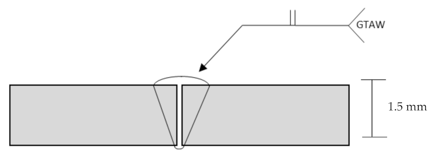
2.1. Sample and Welding
2.2. Microstructure
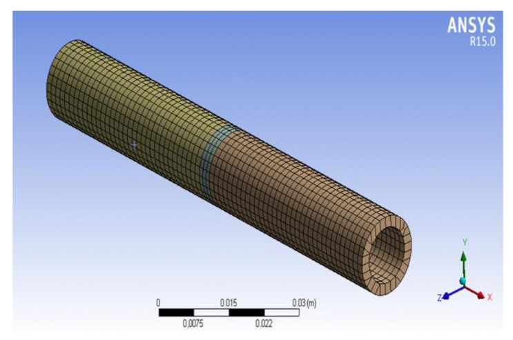
2.3. Finite Element Method Simulation
3. Results
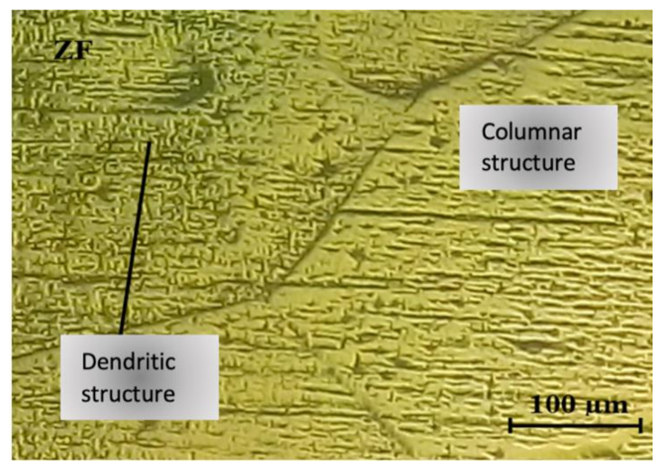
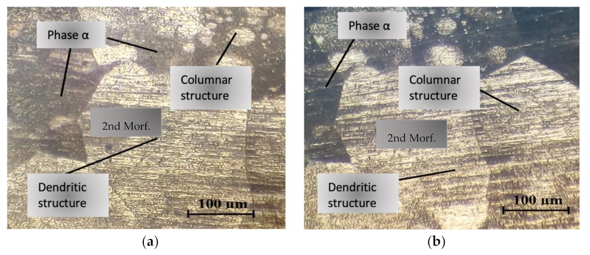
3.1. Microstructural Analysis in the Melted Metal Zone
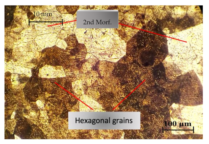
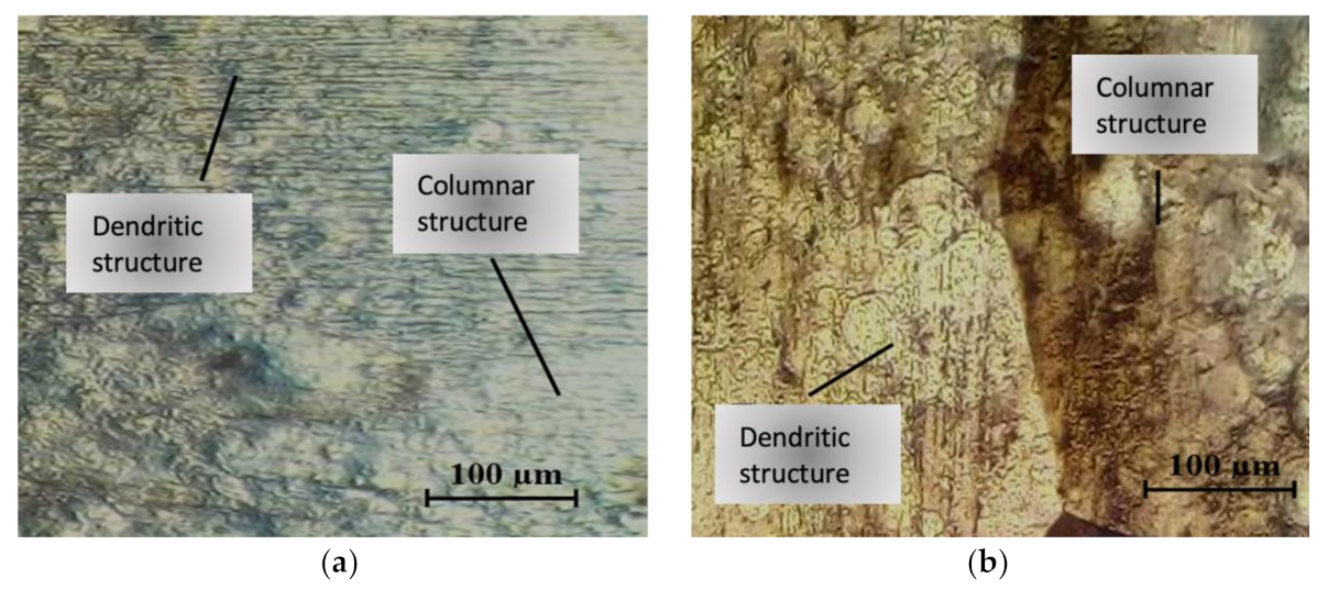
3.2. Microstructural Analysis in the Heat Affected Zone
3.3. Microstructural Analysis of the Fusion Line Interface
3.4. Hardness
4. Discussion
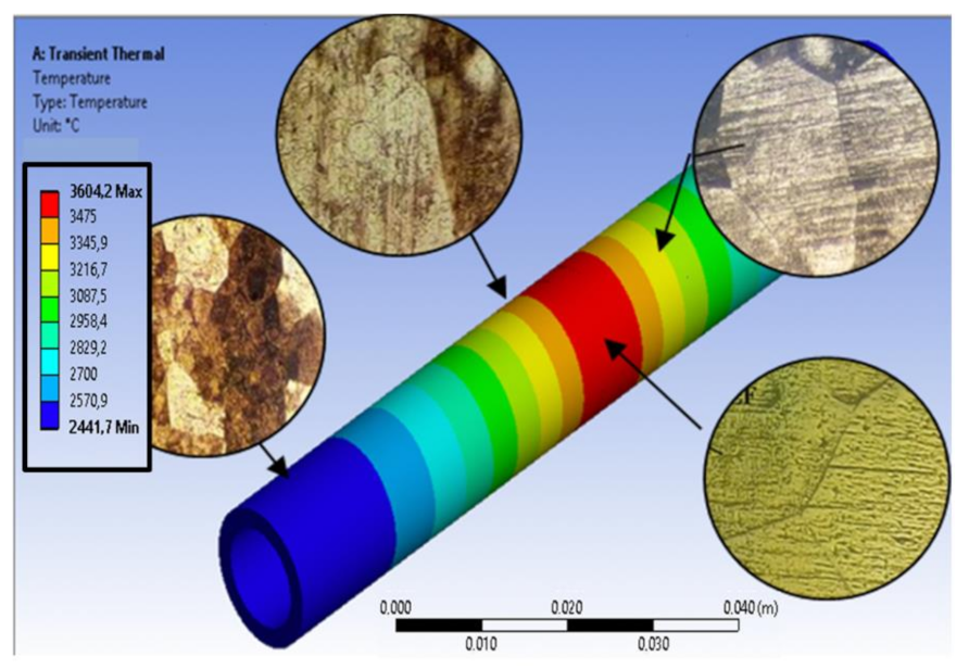
4.1. Weld Process Temperature Distribution
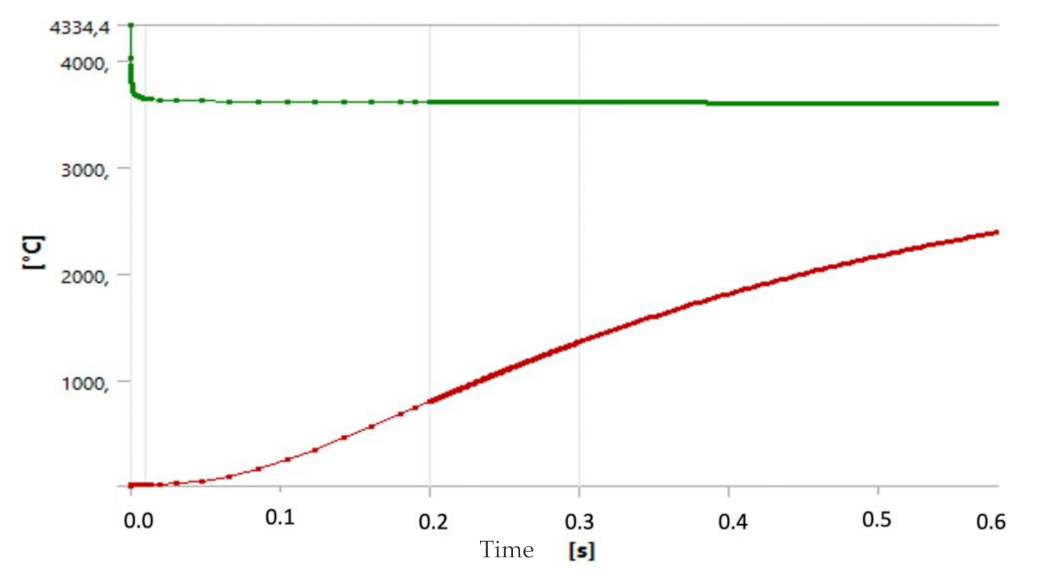
4.2. Temperature Evolution
4.3. Metallographic Study Correlation
5. Conclusions
Author Contributions
Funding
Institutional Review Board Statement
Informed Consent Statement
Data Availability Statement
Acknowledgments
Conflicts of Interest
References
- Kammer, P.A.; Monroe, R.E.; Martin, D.C. Weldability of Tantalum Alloys. 1972. Available online: http://files.aws.org/wj/supplement/WJ_1972_06_s304.pdf (accessed on 24 September 2021).
- Climent, F.; Castella, G. Caracterización de la reacción de oxidación del tantalio a Ta2O5 mediante difracción de rayos X a alta temperatura, análisis térmico y microscopía electrónica de barrido. Bol. Soc. Esp. Cerám. Vidr. 1997, 36, 413–417. [Google Scholar]
- Stelmakh, V.; Rinnerbauer, V.; Geil, R.; Aimone, P.; Senkevich, J.; Joannopoulos, J.; Soljačić, M.; Celanovic, I. High-temperature tantalum tungsten alloy photonic crystals: Stability, optical properties, and fabrication. Appl. Phys. Lett. 2013, 103, 123903. [Google Scholar] [CrossRef] [Green Version]
- Greenberg, B.; Ivanov, M.; Patselov, A.; Besshaposhnikov, Y. The processes of fragmentation, intermixing and fusion upon explosion welding. AASRI Procedia 2012, 3, 66–72. [Google Scholar] [CrossRef]
- Wang, C.; Hang, W. Introduction of tantalum lining pressure vessel. Technol. Wind 2018, 5, 124. [Google Scholar]
- Hashim, F.; Salim, R.; Jaffar, M. On the spot brazing and spot soldering of tantalum. Acad. Res. Int. 2013, 4, 457–467. [Google Scholar]
- Grevey, D.; Vignal, V.; Issam, B.; Erazmus-Vignal, P.; Tomashchuk, I.; Dominique, D.; Sallamand, P. Microstructuraland micro-electrochemical study of a tantalum-titanium weld interface. Mater. Des. 2015, 87, 974–985. [Google Scholar] [CrossRef] [Green Version]
- Zhou, L.; Yuan, T.; Li, R.; Tang, J.; Wang, G.; Guo, K. Selective laser melting of pure tantalum: Densification, microstructure and mechanical behaviors. Mater. Sci. Eng. A 2017, 707, 443–451. [Google Scholar] [CrossRef]
- Jakubowicz, J.; Adamek, G.; Sopata, M.; Koper, J.; Kachlicki, T.; Jarzebski, M. Microstructure and electrochemical properties of refractory nanocrystalline tantalum-based Alloys. Int. J. Electrochem. Sci. 2018, 13, 1956–1972. [Google Scholar] [CrossRef] [Green Version]
- Tang, X. Phase transformations in Ti-Nb-Ta and Ti-Nb-Ta-Zr alloys. Mater. Sci. 2000, 35, 1805–1811. [Google Scholar] [CrossRef]
- Xing, W.; Ye, J.L. Research on welding technology of tantalum cladding of Tantalum steel composite plate. Prog. Ti Ind. 2011, 28, 38–40. [Google Scholar]
- Grill, A. Effect of current pulses on the temperature distribution and microstructure in TIG tantalum welds. Metall. Trans. B 1981, 12, 187–192. [Google Scholar] [CrossRef]
- ASTM E3—11. In Standard Guide for Preparation of Metallographic Specimens; ASTM International: West Conshohocken, PA, USA, 2018.
- ASTM E407—07. In Standard Practice for Micro-Etching Metals and Alloys; ASTM International: West Conshohocken, PA, USA, 2015.
- Magnuson, M.; Greczynski, G.; Eriksson, F.; Hultman, L.; Hogberg, H. Electronic structure of β-Ta films from X-ray photoelectron spectroscopy and first-principles calculations. Appl. Surf. Sci. 2019, 470, 607–612. [Google Scholar] [CrossRef] [Green Version]
- Franco, R.; Loaiza, G.; Lean, P.; Yépez, H. A one coupled thermo-mechanical model to determine residual stresses and deformations in butt welding of two ASTM A36 steel plates. In Proceedings of the VII International Conference on Computational Method for Coupled Problems in Science and Engineering, Rhodes Island, Greece, 12–14 June 2017; Available online: https://upcommons.upc.edu/bitstream/handle/2117/190678/Coupled-2017-67-A%20one%20way%20coupled.pdf (accessed on 17 November 2021).
- Lindgren, L.E. Finite element modeling and simulation of welding. Part 2: Improved material modeling. J. Therm. Stress. 2001, 24, 195–231. [Google Scholar] [CrossRef]
- Xi, S.; Su, Y. Phase Field Study of the Microstructural Dynamic Evolution and Mechanical Response of NiTi Shape Memory Alloy under Mechanical Loading. Materials 2021, 14, 183. [Google Scholar] [CrossRef] [PubMed]
- Li, X.; Su, Y. A phase-field study of the martensitic detwinning in NiTi shape memory alloys under tension or compression. Acta Mech. 2020, 231, 1539–1557. [Google Scholar] [CrossRef]
- ANSYS. Theory Reference. ANSYS Release 5.6, 11th ed.; ANSYS Inc.: Washington County, PA, USA, 1999. [Google Scholar]
- ASTM E92. In Standard Test Methods for Vickers Hardness and Knoop Hardness of Metallic Materials; ASTM International: West Conshohocken, PA, USA, 2017.
- Puhr-Westerheide, J.; Elssner, G. On the solid solution hardening of tantalum by nitrogen and oxygen. J. Less-Common Met. 1970, 20, 371–374. [Google Scholar] [CrossRef]
- Stecura, S. Observation of oxide particles below the apparent oxygen solubility limit in tantalum. Metall. Trans. 1974, 5, 1337–1340. [Google Scholar] [CrossRef] [Green Version]


| Physical Properties | Ta |
|---|---|
| Fusion temperature (K) | 3269 |
| Vaporization temperature (K) | 5698 |
| Density of solid metal (kg/m3) | 15,630 |
| Thermal conductivity of solid (W/m · K) | 57.5 |
| Thermal conductivity of liquid (W/m · K) | 66.5 |
| Specific heat of solid (J/kg · K) | 140 |
| Specific heat of liquid (J/kg · K) | 213 |
| Latent heat of melting (kJ/kg) | 1.7 × 10⁵ |
| Grado | Fe | Si | Nb | W | Ti | O | Cr | H | N | TA |
|---|---|---|---|---|---|---|---|---|---|---|
| B-521 R05200 | 0.003 | 0.003 | 0.028 | 0.004 | 0.002 | 0.010 | 0.0005 | 0.001 | 0.002 | Balance |
| Welding Characteristics and Parameters | - |
|---|---|
| Welding Process | GTAW |
| Filler Material | No |
| Weld layers | 1 |
| Tungsten electrode diameter (mm) | 1 |
| Length of the arc (mm) | 2 |
| Voltage (V) | 11 |
| Intensity (A) | 73 |
| Welding speed (mm/min) | 56 |
| Pre-heating | No |
| Gas (ID-l/min) | Argon- |
| Use of backup | No |
| Welding Position | 1 G |
| Polarity | DCEN |
| Model of the w. machine | Lincoln Aspect 200 |
 | |
|---|---|
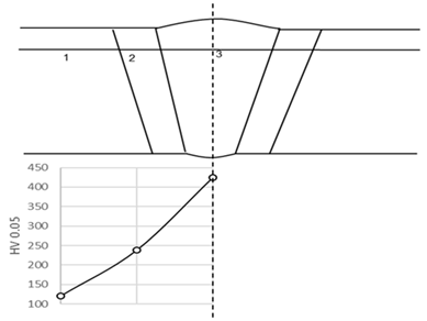
| Zone | Hardness |
| Base Metal (FL + 50 mm) | 120 (120–121) HV 0.05 |
| Heat Affected Zone (FL + 2 mm) | 238 (237–238) HV 0.05 |
| Welded Metal | 425 (425) HV 0.05 |
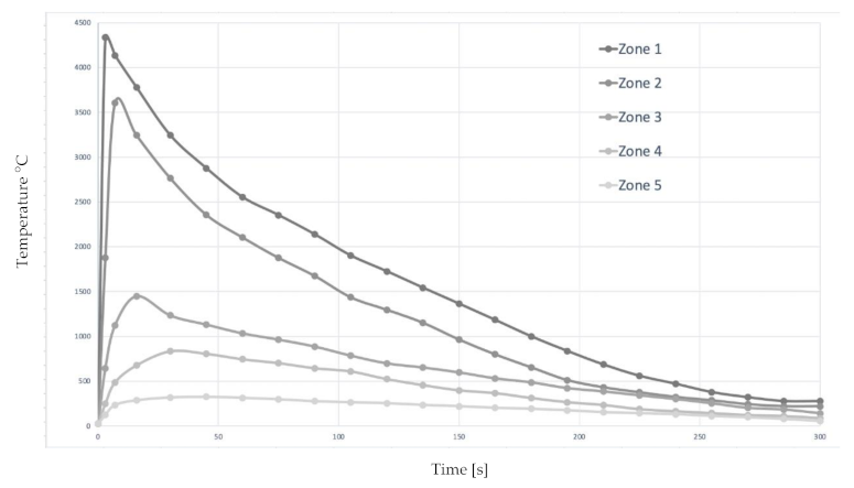
| Zone (See Figure 8) | Max. T. (°C) | Time > 300 °C [s] | Location |
|---|---|---|---|
| (1) Melted metal | <4334.4 | 276 | Joint Point |
| (2) Fusion Line | <3604.2 | 258 | Fusion Line |
| (3) Recrystallization | <1450 | 221 | Fusion Line + 2 mm |
| (4) Grain growth | <850 | 186 | Fusion Line + 5 mm |
| (5) “Base” metal | <300 | 47 | Fusion Line + 50 mm |
Publisher’s Note: MDPI stays neutral with regard to jurisdictional claims in published maps and institutional affiliations. |
© 2022 by the authors. Licensee MDPI, Basel, Switzerland. This article is an open access article distributed under the terms and conditions of the Creative Commons Attribution (CC BY) license (https://creativecommons.org/licenses/by/4.0/).
Share and Cite
Bernardo Sánchez, A.; Presno Vélez, Á.; Fernández-Columbié, T.; Rodríguez-Gonzalez, I.; Suárez Torres, L.; Álvarez de Prado, L.; Menéndez Fernández, M. Tantalum Alloy Welding: Does the Thermal Cycle Influence the Microstructure? Appl. Sci. 2022, 12, 1440. https://doi.org/10.3390/app12031440
Bernardo Sánchez A, Presno Vélez Á, Fernández-Columbié T, Rodríguez-Gonzalez I, Suárez Torres L, Álvarez de Prado L, Menéndez Fernández M. Tantalum Alloy Welding: Does the Thermal Cycle Influence the Microstructure? Applied Sciences. 2022; 12(3):1440. https://doi.org/10.3390/app12031440
Chicago/Turabian StyleBernardo Sánchez, Antonio, Álvaro Presno Vélez, Tomás Fernández-Columbié, Isnel Rodríguez-Gonzalez, Ledennis Suárez Torres, Laura Álvarez de Prado, and Marta Menéndez Fernández. 2022. "Tantalum Alloy Welding: Does the Thermal Cycle Influence the Microstructure?" Applied Sciences 12, no. 3: 1440. https://doi.org/10.3390/app12031440
APA StyleBernardo Sánchez, A., Presno Vélez, Á., Fernández-Columbié, T., Rodríguez-Gonzalez, I., Suárez Torres, L., Álvarez de Prado, L., & Menéndez Fernández, M. (2022). Tantalum Alloy Welding: Does the Thermal Cycle Influence the Microstructure? Applied Sciences, 12(3), 1440. https://doi.org/10.3390/app12031440