Article

Improvement of Heat Transfer Properties through TiO2 Nanosphere Monolayer Embedded Polymers as Thermal Interface Materials

1
Department of Nanoscale Semiconductor Engineering, Hanyang University, Seoul 04763, Korea
2
Department of Electronic Engineering, Hanyang University, Seoul 04763, Korea
*
Author to whom correspondence should be addressed.
These authors contributed equally to this work.
Appl. Sci. 2022, 12(3), 1348; https://doi.org/10.3390/app12031348
Submission received: 24 December 2021 / Revised: 25 January 2022 / Accepted: 25 January 2022 / Published: 27 January 2022
(This article belongs to the Special Issue Advanced Compound Semiconductor)

Abstract

:
A thermal interface material (TIM) is a substance that reduces the thermal resistance between a heat source and heat sink, which facilitates heat conduction towards the outside. In this study, a TiO2 nanosphere (NS)-filler based TIM was fabricated via facile processes such as spin-coating and icing methods. Thermal conductivity of the fabricated TiO2 NS-based TIM was enhanced by increasing the loading contents of the TiO2 NS-filler and successfully cooling down the GPU chipset temperature from 62 °C to 50 °C. Moreover, the TIM with the TiO2 NS-monolayer additionally lowered the GPU temperature by 1–7 °C. The COMSOL simulation results show that the TiO2 NS-monolayer, which was in contact with the heat source, boosts the heat transfer characteristics from the heat source toward the inside of the TIM. The suggested metal oxide monolayer-based TIM is an effective structure that reduces the temperature of the device without an additional filler loading, and it is expected to have a wide range of applications for the thermal management of advanced devices.

1. Introduction

For several decades, the integration of electronic devices to improve system performance has accelerated rapidly. Due to the resulting miniaturization of semiconductor devices, thermal management issues related to electronic components have become increasingly important [1,2]. Especially in small electronic devices, the generated heat significantly affects the efficiency degradation, lifetime, and overall performance. A previous study reported that even a small temperature rise of 10–15 °C in electronic devices reduces the life expectancy by 50% and decreases system reliability [3]. Therefore, heat dissipation control techniques are becoming more important than ever.
In particular, to prevent abnormal temperature rises in such devices, it is necessary to lower the thermal resistance at the contact interface between a chip and heatsink by applying a thermal interface material (TIM). Such a material should have a high thermal conductivity, which decreases the thermal resistance between the chip and heat sink [4,5,6,7,8]. The primary requirements for TIM are high thermal conductivity and stability and low electric conductivity. Among them, high thermal conductivity is the most important parameter, and generally requires using a small loading fraction of fillers, which is becoming important for low-cost and high-efficiency devices [9]. Recently, polymer materials are widely used as TIMs because of their easy processing, light weight, and low cost. However, polymers generally have low thermal conductivity (~0.16 Wm−1K−1) due to the random arrangement of their macromolecular chains [10]. Recently, various research has been conducted to enhance the thermal conductivity of polymer [10,11,12,13,14,15]. For example, Ouyang. et al. used a metal oxide (Al2O3) filler to enhance the thermal conductivity and explained the importance of using a nanosphere filler and nanosphere’s morphology to reduce the phonon scattering between the fillers on an uneven surface [16]. Ma. et al. enhanced the thermal conductivity of polymer (~2.84 Wm−1K−1) using one-dimensional carbon fiber to make a thermal path [17]. However, current polymer-based TIMs do not satisfy the demands of various advanced devices due to the high loading fraction of fillers (>50 wt%), which can degrade the original electrical insulation while increasing the thermal conductivity [14]. Therefore, it is necessary to develop novel structures consisting of materials with low electrical conductivity to achieve efficient heat conduction with low loading of fillers.
Among the generally used fillers, metal oxides such as alumina (Al2O3), copper oxide (CuO), and titanium-dioxide (TiO2) are cheaper and more stable with a lower electrical conductivity than other metals [16,18]. Thus, they are less likely to cause electrical problems in electronic devices after the packaging process. In particular, TiO2 not only has a low electrical conductivity due to its wide bandgap (~3.2 eV at room temperature), but also relatively high thermal conductivity [18,19]. Although these advantages showcased TiO2 as a potential candidate for TIM filler, few studies have been reported.
In this study, we demonstrate the effective improvement of thermal conductivity of TIM by constructing a TiO2 nanosphere (NS)-monolayer structure in a polymer. COMSOL Multiphysics simulations were conducted to explain the thermal conductivity enhancing effect of the monolayer structure, considering complex heat transfer such as conduction, convection, and thermal resistance. The thermal conductivity of the fabricated TiO2 NS-based TIM was enhanced with an increasing loading fraction of the TiO2 NS-filler, and the GPU chipset temperature was lowered from 62 °C to 50 °C. In addition, when the TiO2 NS-monolayer was additionally embedded in TIM, it lowered the GPU temperature by an additional 1–7 °C. In particular, the TiO2 NS-monolayer TIM shows a similar cooling effect to that of the 30 wt% TiO2 NS-filler for the GPU’s temperature. In COMSOL, the reason for the device temperature decrease was confirmed as being due to the large heat absorption by the monolayer. Consequently, the TiO2 NS-monolayer could maintain the chipset at a much lower temperature at the same loading fraction via effective heat absorption from the heat source. These results show that the fabricated TiO2 NS-filler/monolayer structure in polymers is widely applicable in TIMs.

2. Materials and Methods

2.1. Materials

To synthesize TiO2 NSs and form the monolayer, Titanium(IV) isopropoxide (≥97.0%, Sigma Aldrich, St. Louis, MO, USA), methyl amine solution (40 wt% in H2O, Sigma Aldrich), acetonitrile (≥99.8%, Daejung, Siheung, Korea), ethyl alcohol anhydrates (≥99.5%, Daejung), and polydimethylsiloxane (PDMS, Dow Corning, Midland, MI, USA) were used without further purification processes.

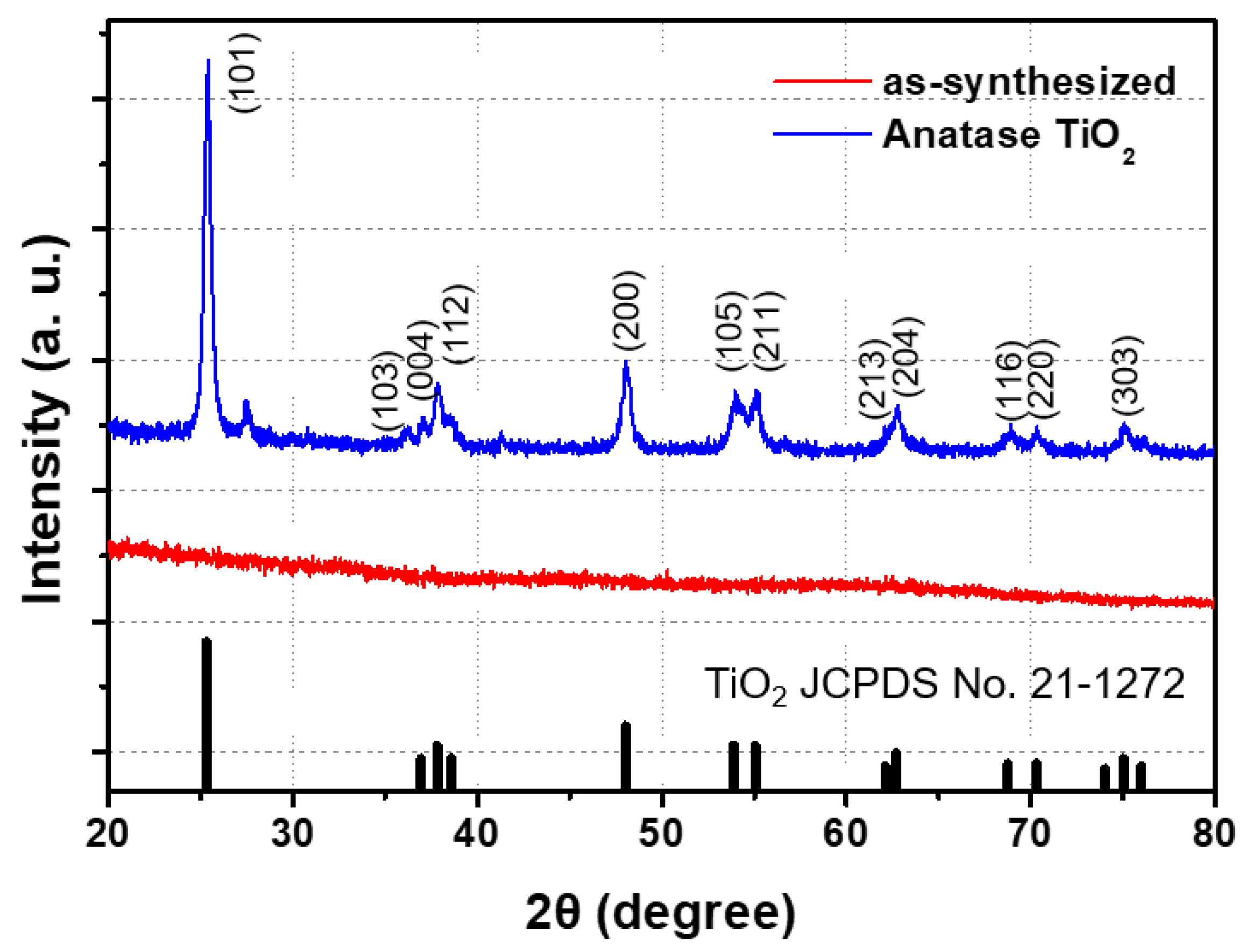
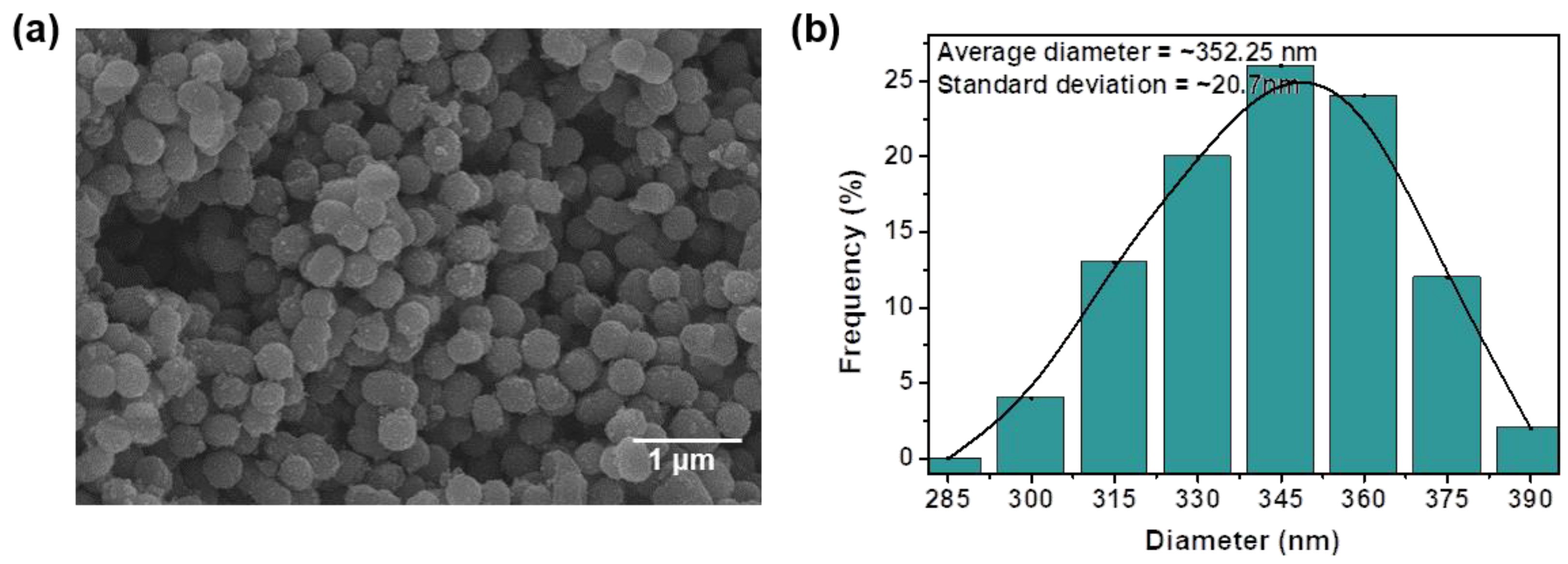
2.2. Synthesis of TiO2 NSs

The TiO2 NS-filler was synthesized using a solution-based synthesis method and two types of solutions were prepared [20,21]. The first solution was prepared by injecting 108 μL of DI water and 5 μL of methylamine solution into a solvent consisting of 80 mL of acetonitrile and 10 mL of ethyl alcohol, and the second solution was prepared by injecting 10 mL of ethanol into 412 μL of titanium (IV) isopropoxide. Both solutions were stirred for 5 min. Then, the first solution was poured into the second solution and stirred quickly for 1 h. After separating and cleaning the formed sediment using a centrifuge, the solution was dried in a 70 °C oven to obtain amorphous TiO2 NS-powder. Then, to obtain anatase TiO2 NS-powder from the as-synthesized amorphous TiO2 NS-powder, heat-treatment at 450 °C for 4 h (heating speed: about 1.8 °C/min) was conducted [22].

2.3. Characterization

To investigate the crystal structures of the synthesized TiO2, X-ray diffraction (XRD) patterns were obtained from the TiO2 NS-powder and analyzed. As shown in Figure 1, there were no XRD peaks for the as-synthesized TiO2 NSs, but after heat treatment, XRD peaks were clearly shown and well-corresponded with the crystal planes of (101), (004), (200), (105), (211), (204), (116), (220), (215), and (303) of anatase TiO2 (JCPDS No. 21-1272) [23]. Consequently, we confirmed that the synthesized amorphous structure of the TiO2 NS was successfully crystallized to an anatase structure after heat treatment.

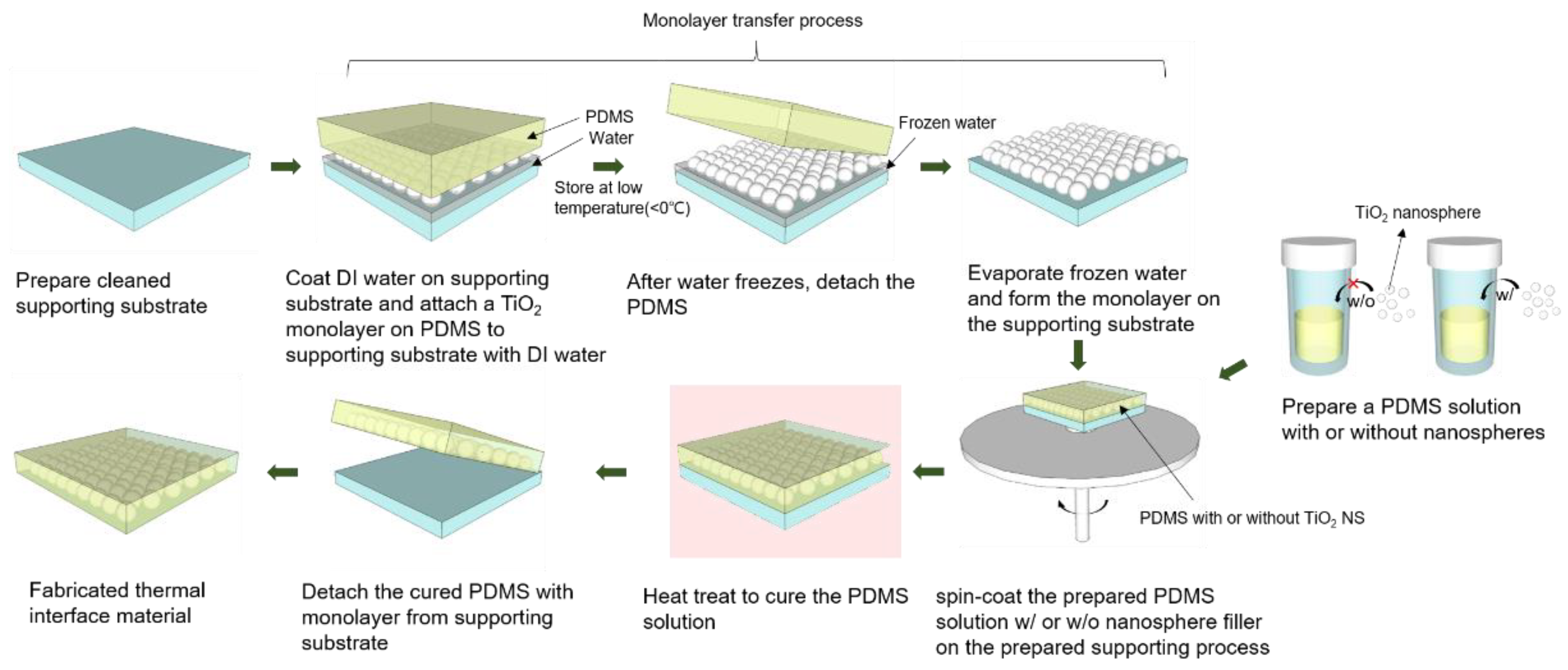
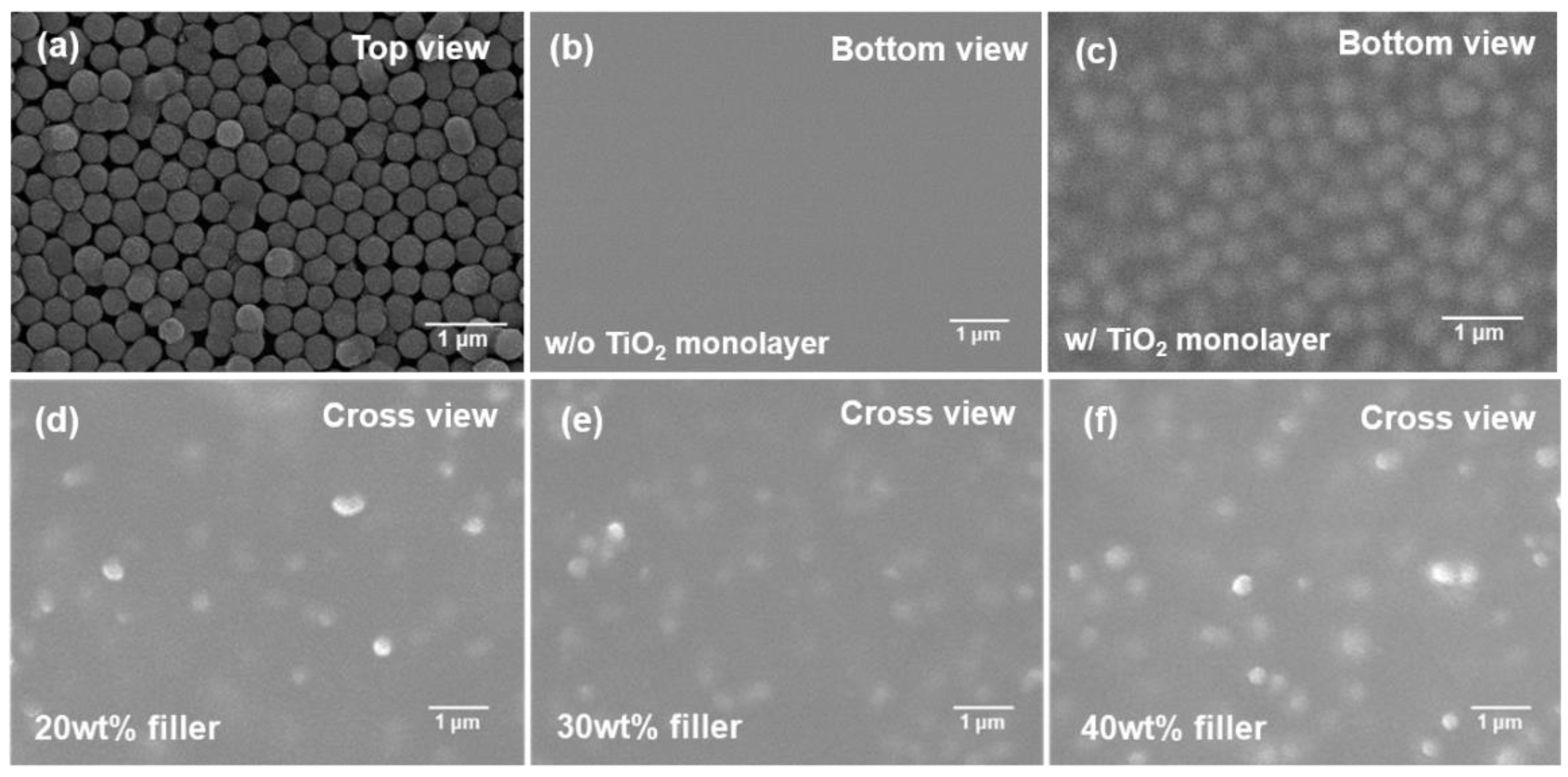
2.4. TIM Fabrication Process

Figure 2 shows the TIM fabrication processes using the obtained anatase TiO2 NS-powder. To transfer the TiO2 NS-monolayer to the supporting substrates, the icing technique was used. At first, a fixed amount of DI water was dropped on the cleaned supporting substrates. Then, the TiO2 NS-monolayer prepared on the PDMS via the unidirectional rubbing method was attached to the supporting substrates and kept at low temperature under 0 °C to freeze the DI water [22]. The frozen DI water can hold the TiO2 NS-monolayer in place for the supporting substrates. After detaching the PDMS from the TiO2 NS-monolayer, the DI water was evaporated on a hotplate at 70 °C. At the same time, the 20 wt%, 30 wt%, and 40 wt% TiO2 NS-powders were mixed in solution with PDMS and curing agent at a mass ratio of 10:1. The obtained mixtures were spin-coated on the TiO2 NS-monolayer transferred supporting substrates at 500 rpm for 10 s and 1000 rpm for 20 s, successively. These spin-coated substances on the supporting substrates were hardened in a 70 °C oven for 1.5 h, then the cured substances were detached from the supporting substrates to complete the fabrication process of the TIM.

2.5. Simulation

The heat conduction simulations of the TiO2 NS-filler/monolayer in PDMS composite were performed using COMSOL Multiphysics 5.6. The selected physics of the heat transfer in the solids and the study was stationary. The TiO2 NS-fillers were built using random functions in the application builders of the development functions to represent the randomly mixed form of the fillers. The thicknesses of the TIMs were 3 µm, the sizes of the spheres were set from 360 nm to 400 nm in diameter, and the numbers of NSs were set to match with the loading fraction of the TiO2 NS-fillers of 20 wt%, 30 wt%, and 40 wt%. The material used for the chipset and heat sink was aluminum. As a boundary condition, a 10−5W quantity of heat was applied to the bottom of the chipset, the initial temperature and ambient temperature were both 20 °C, and 1.5 m/s of air flow was applied along the walls of the heat sink and TIM. The rest interfaces were set to insulation conditions. Additionally, an equivalent thin layer of thermal contact for the given thermal resistance conditions was placed between the substances. The thermal resistance values were 10−7 Km2W−1 between TiO2 and PDMS and 2 × 10⁻⁵Km2W−1 between PDMS and aluminum.

2.6. Measurement and Analysis Conditions

Crystalline structural analysis of the synthesized TiO2 NSs was performed via X-ray diffraction (XRD, Flex600) with a CuKα (λ = 1.5406 Å) light source, and surface images were taken using a scanning electron microscope (FESEM, S-4800). All temperature measurements were conducted at room temperature at about 40% relative humidity conditions.

3. Results and Discussion

To fabricate the new TIM structure, we used a PDMS matrix, TiO2 NS-filler, and TiO2 NS-monolayer. The detailed experimental condition and fabrication processes are described in the materials and methods section. To verify the morphology of the synthesized anatase TiO2 NS, field emission scanning electron microscope (FESEM) measurements were conducted. The synthesized anatase TiO2 NSs showed a spherical shape with diameters of several hundreds of nanometers, as shown in Figure 3a. The diameter distribution of the synthesized TiO2 NSs is shown in Figure 3b, and the average diameter from the diameter distribution is about 352.25 ± 20.7 nm, showing that the synthesized TiO2 NSs have uniform sizes.
To observe the morphology changes of TiO2 NS-based TIMs, FESEM measurements were conducted with various directions of the fabricated TIM samples, as shown in Figure 4. Figure 4a shows the transferred TiO2 NS-monolayer on the rigid support substrate. Figure 4b,c shows the bottom view of PDMS with and without the TiO2 NS-monolayer, respectively. As shown in Figure 4c, it can be confirmed that the TiO2 NS-monolayer was successfully embedded in PDMS, which is clearly seen from Figure 4b. The loading fractions of the TiO2 NS-filler in PDMS were adjusted to 20 wt%, 30 wt%, and 40 wt%, which can be converted to 5.3 vol%, 8.8 vol%, and 13.2 vol% as volume ratios, respectively. Figure 4d–f shows the FESEM cross-sectional images of the fabricated TIMs with different TiO2 NS contents, and the occupancy of TiO2 NS particles according to the change of loading fraction in PDMS can be roughly classified. From the cross-sectional views of the SEM, it should be noted that TiO2 NSs are uniformly distributed inside the PDMS for all embedded conditions.
The fabricated TIMs consisting of the TiO2 NS-filler/monolayer embedded PDMS were attached to the actual GPU chipset to investigate the heat dissipation characteristics. Figure 5a shows the optical photographs of the GPU chipset, fabricated TIMs, heat sink, and cooling fan for the heat dissipation characteristic measurements.
The heat dissipation characteristics of the fabricated TiO2 NS-based TIMs applied in the GPU chipset were compared by increasing the loading fraction of the TiO2 NS-filler from 0 wt% to 20 wt%, 30 wt%, and 40 wt%, with and without the TiO2 NS-monolayer. As shown in Figure 5b, the temperatures of the GPU chipset were gradually decreased with increasing loading fractions of the TiO2 NS-filler from 0 wt% to 40 wt%. In addition, in all cases with the same filler loading fraction, the temperatures of the GPU chipset with the TiO2 NS-monolayer embedded TIM were much lower than those of GPU TIMs without the embedded TiO2 NS-monolayer. In all samples, the thermal conductivities of the TIMs were enhanced by the TiO2 NS-filler, resulting in a lowered GPU chipset temperature from 62 °C to 55 °C with increasing loading fraction of the TiO2 NS-filler from 0 wt% to 40 wt%. More improvements of the thermal dissipation were accomplished by additional embedding of the TiO2 NS-monolayer, lowering the GPU chipset’s temperature by 1–7 °C. Note that only the TiO2 NS-monolayer embedded in PDMS exhibited similar thermal dissipation effects compared with the 30 wt% TiO2 NS-filler. Moreover, 30 wt% TiO2 NS-filler/monolayer embedded in PDMS exhibited almost the same heat dissipation characteristics as the 40 wt% TiO2 NS-filler. It is noteworthy that the loading fraction of the TiO2 in NS-monolayers is only 0.314 wt%. These results indicate that the TiO2 NS-monolayer not only effectively enhances the thermal conductivity of TIM but is also a cost-effective way to achieve a high thermal conductivity of TIM without additional filler loading. Figure 5c shows the working time-dependent temperature variation of the GPU chipset from 0 to 500 s with the fabricated TIMs attached. In all samples, there were abrupt increases in temperature during the initial stages, which then became saturated about 140 s later. In addition, the maximum measured temperatures of the GPU chipset decreased as the loading fraction of the TiO2 NS-filler in the PDMS increased, with a tendency to decrease further in the presence of the TiO2 NS-monolayer.
To theoretically investigate the thermal conductivity enhancement of TIMs by a TiO2 NS-monolayer, a computer simulation was used with COMSOL Multiphysics 5.6. The simulations were conducted on the premise that the lowest saturation temperature model has the highest thermal conductivity. The quantity of heat applied to the chipset and the air flow speed applied to the heat sink were fixed considering typical cooling fan speeds (Ø150 mm, 1200 rpm) and detailed values are described in the materials and methods Section 2.3. For more accurate analysis, the thermal resistances between the PDMS, TiO2 NSs, chipset, and heat sink should be considered based on the contact interface conditions [24]. The thermal resistances between the chipset and TIM and the TIM and heat sink were set to relatively high values of 2 × 10⁻⁵ Km2W−1 because they have solid-solid contact interfaces with air gaps due to the surface roughness [25,26]. TiO2 NSs and PDMS form relatively stable interfaces because they are mixed and hardened in a liquid state [27]. Thus, the thermal resistance between TiO2 NSs and PDMS was 10−7 Km2W−1, a relatively low value [28]. Figure 6a shows the heat conduction characteristics of TIMs with bare PDMS, 20 wt% TiO2 NS-filler in PDMS, and 20 wt% TiO2 NS-filler/monolayer in PDMS at the same temperature scale. The heat conduction enhancement due to the NS-monolayer was clearly observed by comparing the average temperatures of the chipset and TIM. The ratio of the temperature difference between the two substances forming an interface can be described as follows:
Temperature   difference   ratio = T heat   source T TIM T TIM × 100   [ % ] ,
where Theat source and TTIM are the steady-state temperature of the heat source (chipset) and TIM, respectively. The large temperature difference indicates that there is a large contact resistance, which can impede heat conductions between the chipset and TIM, causing heat to be trapped in the heat source. The case of bare PDMS without any TiO2 NS embedded shows that the temperatures of the chipset and TIM were 67.18 °C and 44.83 °C, respectively, which is about a 50% temperature difference ratio between them. This means that the applied heat could not be easily transferred from the chipset to TIM due to the heat trapped inside the chipset because of the high thermal resistance between them. In the case of TIM with the 20 wt% TiO2 NS-filler in PDMS, the temperatures of the chipset and TIM were lowered to 58.19 °C and 44.83 °C, respectively, with a temperature difference ratio of about 37.7% between the chipset and TIM. Meanwhile, TIM with the 20 wt% TiO2 NS- filler/monolayer in PDMS maintained a chipset temperature of 45.18 °C and TIM temperature of 40.58 °C, which were not only the lowest temperatures among the samples but exhibited a reduced temperature difference of only 11.3%. These smallest temperature differences indicate that the TiO2 NS-monolayer results in low interface thermal resistance and efficient heat conduction, as shown in Figure 6a. Based on these results, simulations were conducted successively by changing of the TiO2 NS-filler loading fraction from 0 wt% to 20 wt%, 30 wt%, and 40 wt%, with and without the TiO2 NS-monolayer. The thermal conductivities of fabricated TIMs were enhanced, which lowered the chipset temperature by about 20.3% (from 59 °C to 47 °C) with increasing loading fractions of the TiO2 NS-filler from 0% to 40 wt%; additional heat dissipation enhancement via inclusion of the TiO2 NS-monolayer lowered the chipset temperature by an additional 10–15% compared to TIMs without the TiO2 NS-monolayer. The increased thermal conductivity was affected by the TiO2 NS-monolayer for all filler loading fractions, as evidenced through the lowered chipset temperatures and experimental results.
The detailed heat transfer processes between the chipset and TIM with TiO2 NS-filler/monolayer are considered in Figure 7. The increase in thermal conductivity and reduction in thermal resistance at the interface due to the TiO2 NS-monolayer can be attributed to how the embedded TiO2 NSs can maximize the effects of heat absorption from the heat source. In the case of TiO2 NSs embedded in PDMS TIMs without a TiO2 NS-monolayer, the heat absorption from the heat source is not easily observed due to the high thermal resistance of uneven contact points between the chipset and TIM, as well as the poor thermal conductivity of PDMS [29]. Moreover, the relatively small area for heat conduction from the chipset to TIM due to the limited contact interface between them hindered effective heat dissipation [30]. However, the TiO2 NS-monolayer with TIM can absorb large quantities of heat with higher thermal conductivity than PDMS. In this way, the absorbed heat can be released into the TIM through a large surface contact area with the TiO2 NS-monolayer. The released heat is transferred outside following the heat path formed by the TiO2 NS-filler, which can result in strong cooling effects on electronic devices without additional loading fraction changes of the TiO2 NS-filler [31]. Consequently, the suggested facile TiO2 monolayer embedding method is an effective way to fabricate a low-cost and high-performance TIM, which has enormous potential for heat dissipation technology.

4. Conclusions

In summary, TiO2 NS-filler/monolayer-based TIMs were fabricated by spin-coating a TiO2 NS/PDMS mixture on a TiO2 NS-monolayer with transfer via the icing method. The thermal conductivities of the TIMs were enhanced by increasing the loading fractions of the TiO2 NS-fillers in PDMS from 0 wt% to 40 wt%, which lowered the GPU chipset temperature from 62 °C to 50 °C. In all TiO2 NS/PDMS fillers with different loading fractions, it was found that an additional TiO2 NS-monolayer improved the thermal conductivity of TIM and lowered the GPU chipset temperature by about 1–7 °C compared to TIMs without an NS-monolayer. The interesting thing is that including only the TiO2 NS-monolayer in PDMS (0 wt% filler) achieved dramatic heat conduction improvement, similar to that for the 30 wt% TiO2 NS-filler in PDMS. The thermal conductivity enhancement via the TiO2 NS-monolayer was analyzed using simulations via COMSOL Multiphysics 5.6. The TiO2 NS-monolayer can effectively absorb larger quantities of heat from the heat source than polymers with small thermal resistance, and can effectively dissipate the absorbed heat to the outside because of the large surface areas of the spheres. Based on our results and considering that the TiO2 NS-monolayer’s loading fraction is only 0.314 wt%, the TIM consisting of TiO2 NSs and an NS-monolayer provides an efficient way to achieve higher thermal conductivity with low additional filler loading. Our proposed metal oxide NS-monolayer structure has great potential for improving TIM performance.

Author Contributions

Investigation, writing-original draft preparation, data curation and software, J.M. and U.J.; methodology and validation, B.J.; writing-review and editing, supervision, project administration, funding acquisition, J.P. All authors have read and agreed to the published version of the manuscript.

Funding

This research was funded by a National Research Foundation of Korea (NRF) grant funded by the Korean government (MSIT) (No. 2021R1A4A10520850) and Samsung Electronics Co., Ltd. (Suwon-si, Korea).

Institutional Review Board Statement

Not applicable.

Informed Consent Statement

Not applicable.

Data Availability Statement

The data presented in this study are available on request from the corresponding author.

Conflicts of Interest

The authors declare no conflict of interest.

References

  1. Waldrop, M.M. The chips are down for Moore’s law. Nat. News 2016, 530, 144. [Google Scholar] [CrossRef] [PubMed] [Green Version]
  2. Moore, A.L.; Shi, L. Emerging challenges and materials for thermal management of electronics. Mater. Today 2014, 17, 163–174. [Google Scholar] [CrossRef]
  3. Chen, H.; Ginzburg, V.V.; Yang, J.; Yang, Y.; Liu, W.; Huang, Y.; Du, L.; Chen, B. Thermal conductivity of polymer-based composites: Fundamentals and applications. Prog. Polym. Sci. 2016, 59, 41–85. [Google Scholar] [CrossRef]
  4. Chung, D. Thermal interface materials. J. Mater. Eng. Perform. 2001, 10, 56–59. [Google Scholar] [CrossRef]
  5. Prasher, R. Thermal interface materials: Historical perspective, status, and future directions. Proc. IEEE 2006, 94, 1571–1586. [Google Scholar] [CrossRef]
  6. Zhou, Y.; Wu, S.; Long, Y.; Zhu, P.; Wu, F.; Liu, F.; Murugadoss, V.; Winchester, W.; Nautiyal, A.; Wang, Z. Recent advances in thermal interface materials. ES Mater. Manuf. 2020, 7, 4–24. [Google Scholar] [CrossRef]
  7. Zhang, Y.; Ma, J.; Wei, N.; Yang, J.; Pei, Q.-X. Recent progress in the development of thermal interface materials: A review. Phys. Chem. Chem. Phys. 2021, 23, 753–776. [Google Scholar] [CrossRef]
  8. Razeeb, K.M.; Dalton, E.; Cross, G.L.W.; Robinson, A.J. Present and future thermal interface materials for electronic devices. Int. Mater. Rev. 2018, 63, 1–21. [Google Scholar] [CrossRef]
  9. Ma, H.; Gao, B.; Wang, M.; Yuan, Z.; Shen, J.; Zhao, J.; Feng, Y. Strategies for enhancing thermal conductivity of polymer-based thermal interface materials: A review. J. Mater. Sci. 2021, 56, 1064–1086. [Google Scholar] [CrossRef]
  10. Hansson, J.; Nilsson, T.M.; Ye, L.; Liu, J. Novel nanostructured thermal interface materials: A review. Int. Mater. Rev. 2018, 63, 22–45. [Google Scholar] [CrossRef]
  11. Tan, X.; Ying, J.; Gao, J.; Yan, Q.; Lv, L.; Nishimura, K.; Wei, Q.; Li, H.; Du, S.; Wu, B. Rational design of high-performance thermal interface materials based on gold-nanocap-modified vertically aligned graphene architecture. Compos. Commun. 2021, 24, 100621. [Google Scholar] [CrossRef]
  12. Zhao, M.; Feng, X.; Zhu, W.; Guo, W.; Wang, G.; Liu, Z.; Guo, Q.; Chen, D. 2D Graphene in Interface Engineering of 3D Graphene-Based Thermal Management. Phys. Status Solidi 2021, 218, 2000576. [Google Scholar] [CrossRef]
  13. Loeblein, M.; Tsang, S.H.; Pawlik, M.; Phua, E.J.R.; Yong, H.; Zhang, X.W.; Gan, C.L.; Teo, E.H.T. High-density 3D-boron nitride and 3D-graphene for high-performance nano–thermal interface material. ACS Nano 2017, 11, 2033–2044. [Google Scholar] [CrossRef] [PubMed]
  14. Song, Q.; Zhu, W.; Deng, Y.; Hai, F.; Wang, Y.; Guo, Z. Enhanced through-plane thermal conductivity and high electrical insulation of flexible composite films with aligned boron nitride for thermal interface material. Compos. Part A Appl. Sci. Manuf. 2019, 127, 105654. [Google Scholar] [CrossRef]
  15. Zhang, W.; Kong, Q.Q.; Tao, Z.; Wei, J.; Xie, L.; Cui, X.; Chen, C.M. 3D thermally cross-linked graphene aerogel–enhanced silicone rubber elastomer as thermal interface material. Adv. Mater. Interfaces 2019, 6, 1900147. [Google Scholar] [CrossRef]
  16. Ouyang, Y.; Bai, L.; Tian, H.; Li, X.; Yuan, F. Recent progress of thermal conductive ploymer composites: Al2O3 fillers, properties and applications. Compos. Part A Appl. Sci. Manuf. 2022, 152, 106685. [Google Scholar] [CrossRef]
  17. Ma, J.; Shang, T.; Ren, L.; Yao, Y.; Zhang, T.; Xie, J.; Zhang, B.; Zeng, X.; Sun, R.; Xu, J.-B. Through-plane assembly of carbon fibers into 3D skeleton achieving enhanced thermal conductivity of a thermal interface material. Chem. Eng. J. 2020, 380, 122550. [Google Scholar] [CrossRef]
  18. Tavman, I.; Turgut, A. An investigation on thermal conductivity and viscosity of water based nanofluids. In Microfluidics Based Microsystems; Springer: Dordrecht, The Netherlands, 2010; pp. 139–162. [Google Scholar]
  19. Dette, C.; Pérez-Osorio, M.A.; Kley, C.S.; Punke, P.; Patrick, C.E.; Jacobson, P.; Giustino, F.; Jung, S.J.; Kern, K. TiO2 anatase with a bandgap in the visible region. Nano Lett. 2014, 14, 6533–6538. [Google Scholar] [CrossRef]
  20. Yu, W.; Yuan, S.; Li, Y.; Zhang, Q.; Wang, H. Preparation of TiO2 nanoparticle/nanotube composites via a vapor hydrolysis method and their photocatalytic activities. Int. Sch. Res. Not. 2011, 2011, 582534. [Google Scholar] [CrossRef] [Green Version]
  21. Moon, J.T.; Lee, S.K.; Joo, J.B. Controllable one-pot synthesis of uniform colloidal TiO2 particles in a mixed solvent solution for photocatalysis. Beilstein J. Nanotechnol. 2018, 9, 1715–1727. [Google Scholar] [CrossRef] [Green Version]
  22. Yang, T.; Park, S.-j.; Kim, T.G.; Shin, D.S.; Park, J. Ultraviolet photodetector using pn junction formed by transferrable hollow n-TiO2 nano-spheres monolayer. Opt. Express 2017, 25, 30843–30850. [Google Scholar] [CrossRef] [PubMed]
  23. Dong, Y.; Fei, X.; Liu, Z.; Zhou, Y.; Cao, L. Synthesis and photocatalytic redox properties of anatase TiO2 single crystals. Appl. Surf. Sci. 2017, 394, 386–393. [Google Scholar] [CrossRef]
  24. Narumanchi, S.; Mihalic, M.; Kelly, K.; Eesley, G. Thermal interface materials for power electronics applications. In Proceedings of the 2008 11th Intersociety Conference on Thermal and Thermomechanical Phenomena in Electronic Systems, Orlando, FL, USA, 28–31 May 2008; pp. 395–404. [Google Scholar]
  25. Swartz, E.; Pohl, R. Thermal resistance at interfaces. Appl. Phys. Lett. 1987, 51, 2200–2202. [Google Scholar] [CrossRef]
  26. Zhao, J.-W.; Zhao, R.; Huo, Y.-K.; Cheng, W.-L. Effects of surface roughness, temperature and pressure on interface thermal resistance of thermal interface materials. Int. J. Heat Mass Transf. 2019, 140, 705–716. [Google Scholar] [CrossRef]
  27. Xue, L.; Keblinski, P.; Phillpot, S.; Choi, S.-S.; Eastman, J. Two regimes of thermal resistance at a liquid–solid interface. J. Chem. Phys. 2003, 118, 337–339. [Google Scholar] [CrossRef]
  28. Maruyama, S.; Kimura, T. A study on thermal resistance over a solid-liquid interface by the molecular dynamics method. Therm. Sci. Eng 1999, 7, 63–68. [Google Scholar]
  29. Grujicic, M.; Zhao, C.; Dusel, E. The effect of thermal contact resistance on heat management in the electronic packaging. Appl. Surf. Sci. 2005, 246, 290–302. [Google Scholar] [CrossRef]
  30. Kumar, D.H.; Patel, H.E.; Kumar, V.R.; Sundararajan, T.; Pradeep, T.; Das, S.K. Model for heat conduction in nanofluids. Phys. Rev. Lett. 2004, 93, 144301. [Google Scholar] [CrossRef] [Green Version]
  31. Bergles, A.E. Recent developments in enhanced heat transfer. Heat Mass Transf. 2011, 47, 1001–1008. [Google Scholar] [CrossRef]
Figure 1. XRD patterns of the synthesized TiO2 NS before and after heat treatment.
Applsci 12 01348 g001
Figure 2. Schematic of the fabrication process for the PDMS-based TIM with the TiO2 NS-filler and monolayer.
Applsci 12 01348 g002
Figure 3. (a) FESEM image of the synthesized anatase TiO2 NSs and (b) their size distribution histogram.
Applsci 12 01348 g003
Figure 4. FESEM images of the (a) transferred TiO2 NS-monolayer on the supporting substrate, bottom view of the PDMS (b) without and (c) with the TiO2 NS-monolayer. (df) Cross-sectional images of the suggested TIM with TiO2 NS-filler concentrations of (d) 20 wt%, (e) 30 wt%, and (f) 40 wt%.
Applsci 12 01348 g004
Figure 5. (a) Optical photographs of the GPU chipset and heatsink set with the fabricated TiO2 NS-based TIM. (b) The saturation temperature and (c) time-dependent temperature variations of the GPU chipset according to the concentration of TiO2 NS-filler with and without the TiO2 NS-monolayer in PDMS matrix as the TIM. (Insets in Figure 5b are optical photographs of the fabricated TiO2 NS-based TIMs.).
Applsci 12 01348 g005
Figure 6. (a) The typical simulated thermal distribution results according to the presence or absence of the TiO2 NS-filler (20 wt%) and monolayer in PDMS matrix. (b) The simulated temperature (at steady-state) of heat sources according to concentration of the TiO2 NS-filler with and without TiO2 NS-monolayer in PDMS matrix as the TIM.
Applsci 12 01348 g006
Figure 7. Schematic illustrations of the heat conduction process with the absence or presence of TiO2 NS-fillers and -monolayers in PDMS matrix.
Applsci 12 01348 g007
Publisher’s Note: MDPI stays neutral with regard to jurisdictional claims in published maps and institutional affiliations.

