1. Introduction
The French tokamak WEST, located in Cadarache, South of France, is an upgrade of the Tore Supra tokamak, which achieved first plasma in 1988 [
1]. After leading plasma control for long pulse operations for 25 years, the initial toroidal carbon limiter of this tokamak has been turned into a tungsten divertor to support ITER design and operation with this specific plasma facing material.
WEST is a medium-sized tokamak (R = 2.5 m, a = 0.5 m, Bt = 3.7 T). Its two main objectives are to study the behavior of ITER representative tungsten plasma facing components in a divertor configuration, as well as to control plasma for long pulses (~1000 s) in a metallic environment.
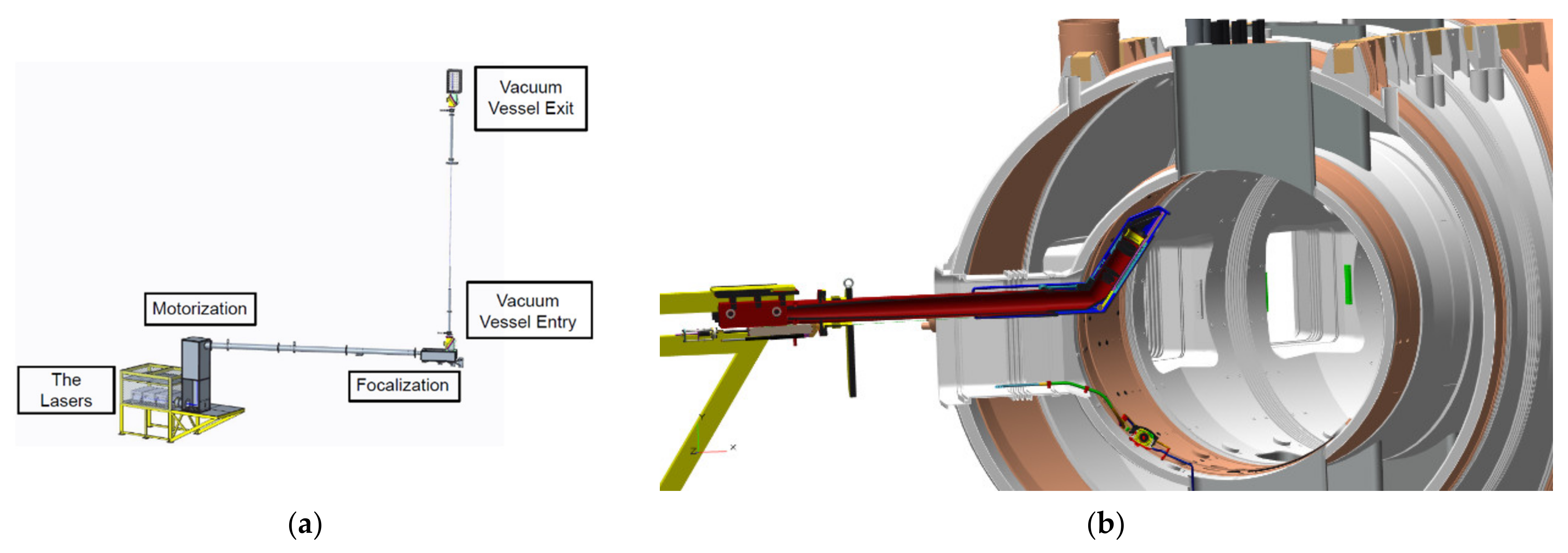
In order to measure plasma density and temperature profiles in WEST, IRFM is designing a new Thomson Scattering diagnostic (
Figure 1) with a radial resolution of few millimeters inside the pedestal [
2,
3,
4].
The design of the diagnostic is based on two key points: the interaction between the laser beams and the plasma and the collection of the scattered light by the endoscope.
Up to three lasers of 2 J at 30 Hz will be installed under the tokamak. The focused laser beams will come into the vacuum vessel from below and through a Brewster window. The scattered light, which is the result of the interaction between the laser beams and the plasma, will be transported by optical fibers to polychromators located below the tokamak. After vertically crossing the tokamak, the laser beams will be stopped by a laser dump, and the main characteristics of the beams will be analyzed by a control box.
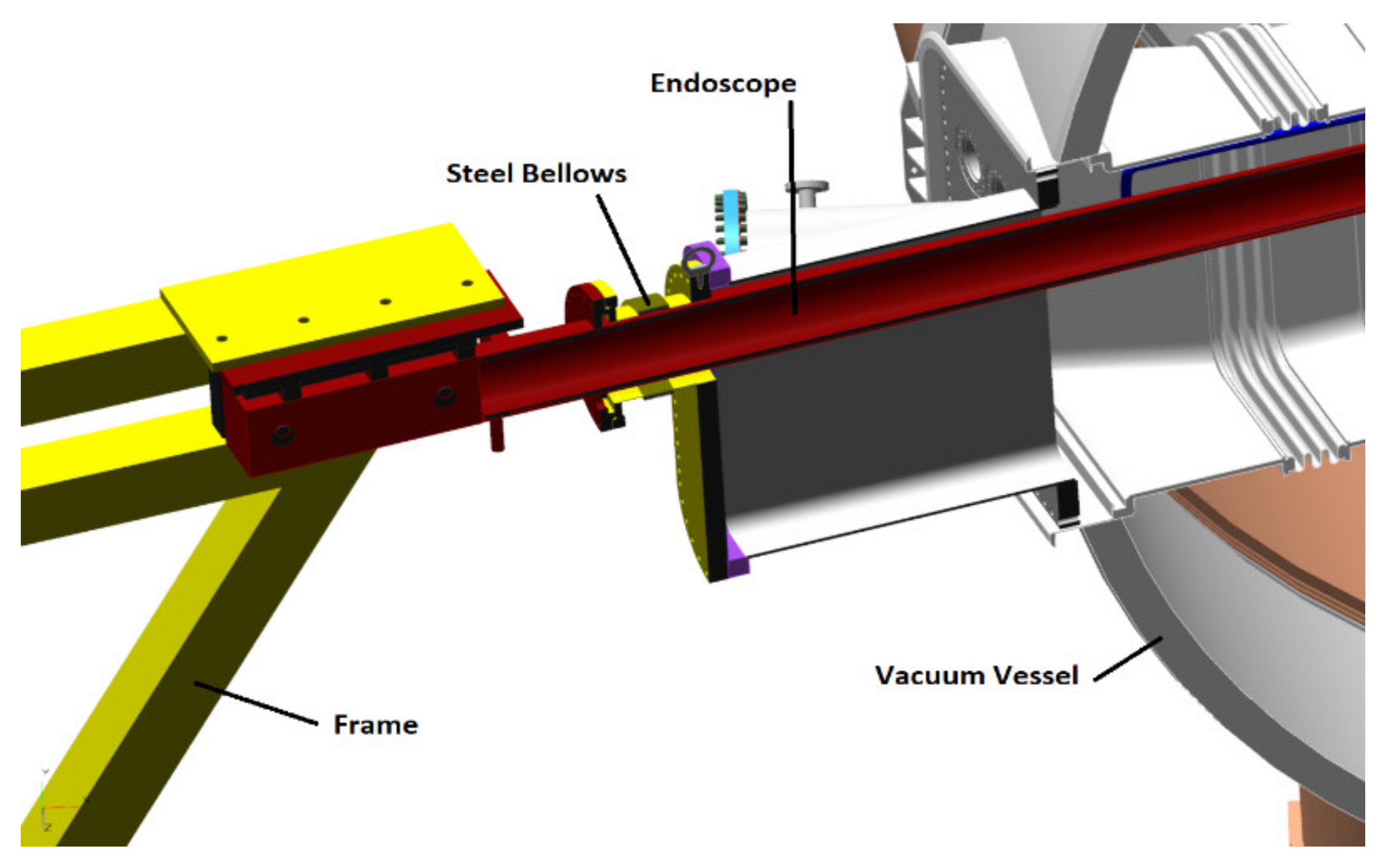
An endoscope inside the vacuum vessel, using actively cooled optical components, would allow for high spatial resolution inside the pedestal. The rear part of the endoscope will be attached on a frame, fixed in turn to the building to make the endoscope and the tokamak mechanically independent of each other. To do so, at the level of the vacuum flange, a stainless steel bellows will be used to ensure vacuum tightness while keeping the endoscope free from the vacuum vessel movements (
Figure 2).
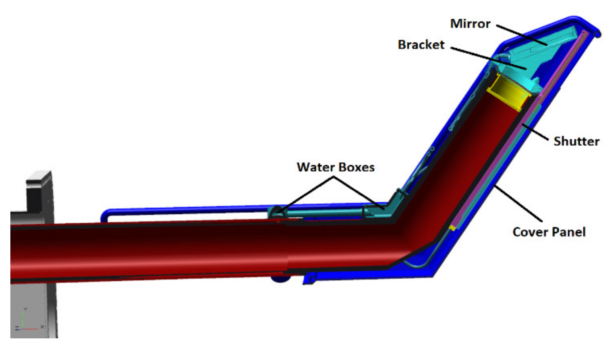
The optical system, composed of an actively cooled mirror, is located at the front part of the endoscope (placed inside the vacuum vessel), its bracket and a lens system allowing for focalization in the optical fibers (
Figure 3). To ensure viability of the measurements, the tilt of the mirror needs to be calculated.
Temperature is also another important parameter to be taken into account, since this diagnostic operates in the near infrared light. To avoid stray radiation, the temperature of all components must be kept lower than 200 °C.
In this study, mechanical, thermal, hydraulic and electromagnetic aspects are considered to evaluate the efficiency of the endoscope. Global and local calculations have been carried out in order to understand the behavior of critical components and to validate the whole design before launching a call for tenders for manufacturing.
2. Materials and Methods
2.1. Materials
First, 316 L stainless steel was used for all the bodies inside the vacuum vessel due to its good antimagnetic properties, as well as its resistance to corrosion. Only the frame outside the vacuum vessel was manufactured in standard steel S235.
Physical and mechanical properties have been selected according to the European standards NF-EN 13445-2 [
5], 10028-7 [
6] and 10088-1 [
7].
2.2. Criteria
To validate and guarantee the diagnostic performances, the criteria described in the following paragraphs need to be checked during plasma operation. No measurements are foreseen during incidental and accidental events.
2.2.1. Operation Criteria
The optical system, including the mirror, is the key component of the diagnostic. The perpendicular displacement of the optical surface shall not be higher than 40 µm (peak-to-peak). Moreover, the tilt shall be studied in depth to check it is lower than 6 arcmin [
8]. At the mirror location, the directional deformation in the vertical axis should not be higher than 6 mm.
This diagnostic operates in near infrared light; thus, the temperature of all components must stay lower than 200 °C as not to bias the measurements. To do so, all the endoscope components will be actively cooled by pressurized water (70–100 °C, 36 bar).
The water temperature difference between the inlet and outlet of the diagnostic should be lower than 50 °C. The water pressure difference between the inlet and outlet of the diagnostic must be lower than 5.6 bar.
The diagnostic is surrounded by vibratory components, such as pumps or the plasma itself. In order to avoid resonance, the natural frequencies of the structure must be higher than 20 Hz as well as far enough from the frequency of external components. The plasma oscillates at a frequency of 600 Hz, while two other diagnostics with vacuum pumps are close to the Thomson scattering diagnostic (frequencies to be avoided are 80, 450 and 833 Hz).
2.2.2. Allowable Stress
The allowable stress values in the structure are determined from the European standards NF-EN 13445-3 [
9].
The admissible stress during normal operations is:
where
is the yield strength at 0.2% at the calculation temperature, and
is the tensile strength at 20 °C.
The allowable stress in the structure must comply with the following recommendations:
where
represents the stress resulting from primary loads (mechanical) and
from secondary loads (thermal).
2.3. Normal Operation Plasma Scenario
2.3.1. Global Analysis
A steady-state structural analysis was carried out for all the structure, from the frame to the head of the endoscope.
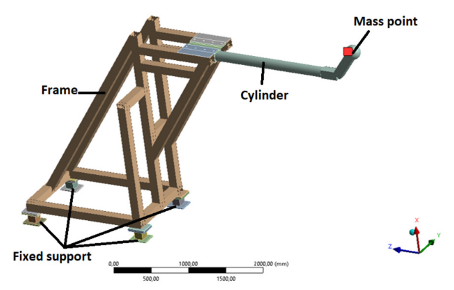
The frame is represented by beam elements. The four legs of the frame are completely fixed. The cylinder, composed of two welded tubes, is represented by a single cylinder to ensure moment of inertia and mass conservation. To be conservative, a mass point representative of small components (mirror, bracket, shutter and cover panel) is located at the end of the endoscope (
Figure 4).
The aim of this global analysis is to evaluate the tilt at the mirror’s location, along with the stress in the structure during normal operation.
The boundary conditions are:
2.3.2. Local Analysis
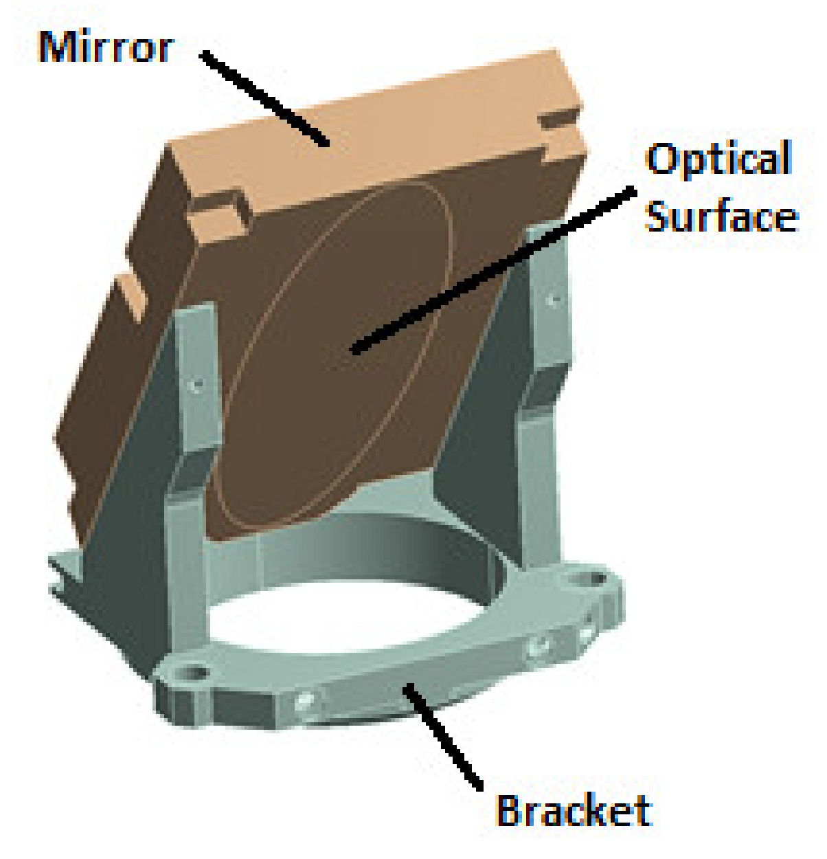
A local study of the mirror and its bracket (
Figure 5) has been carried out to evaluate the local displacement of the mirror and the temperature profile inside these two components, independently from the rest of the structure.
This study is divided into two steps:
A thermal–hydraulic analysis by means of CFD (computational fluid dynamics) method, in order to derive temperature and pressure gradients;
A structural steady-state analysis using FEM (finite element method) in order to check optical and mechanical criterions.
The CFD results (temperature profile of structural bodies, pressure in fluid–structure interfaces) obtained in the first step have were as input data for the second step of FEM calculation.
The plasma heat flux value is calculated from plasma radiation data [
10] considering appropriate form factor and surface reflectivity (reflectivity of 0.925 for mirror face and 0.65 for all others faces).
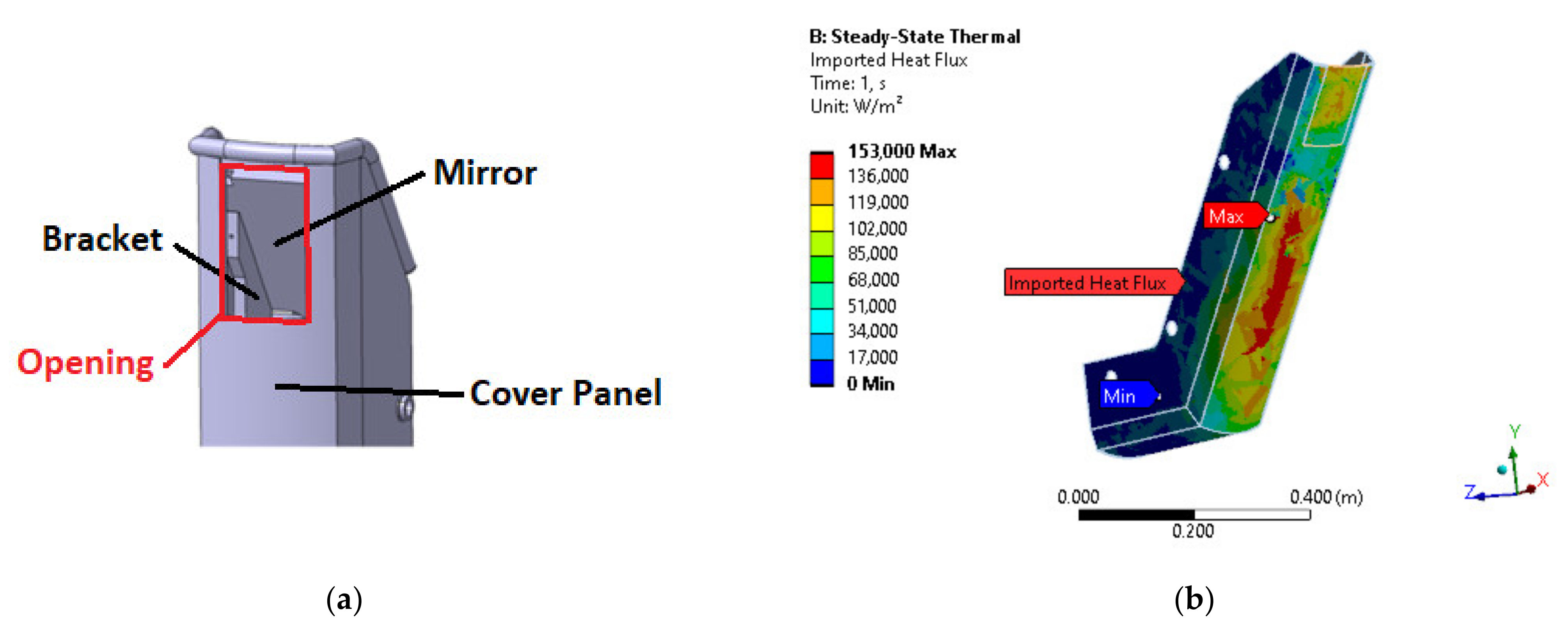
Figure 6 illustrates the opening for plasma radiation (a) as well as the plasma heat flux distribution for the worst-case scenario (b).
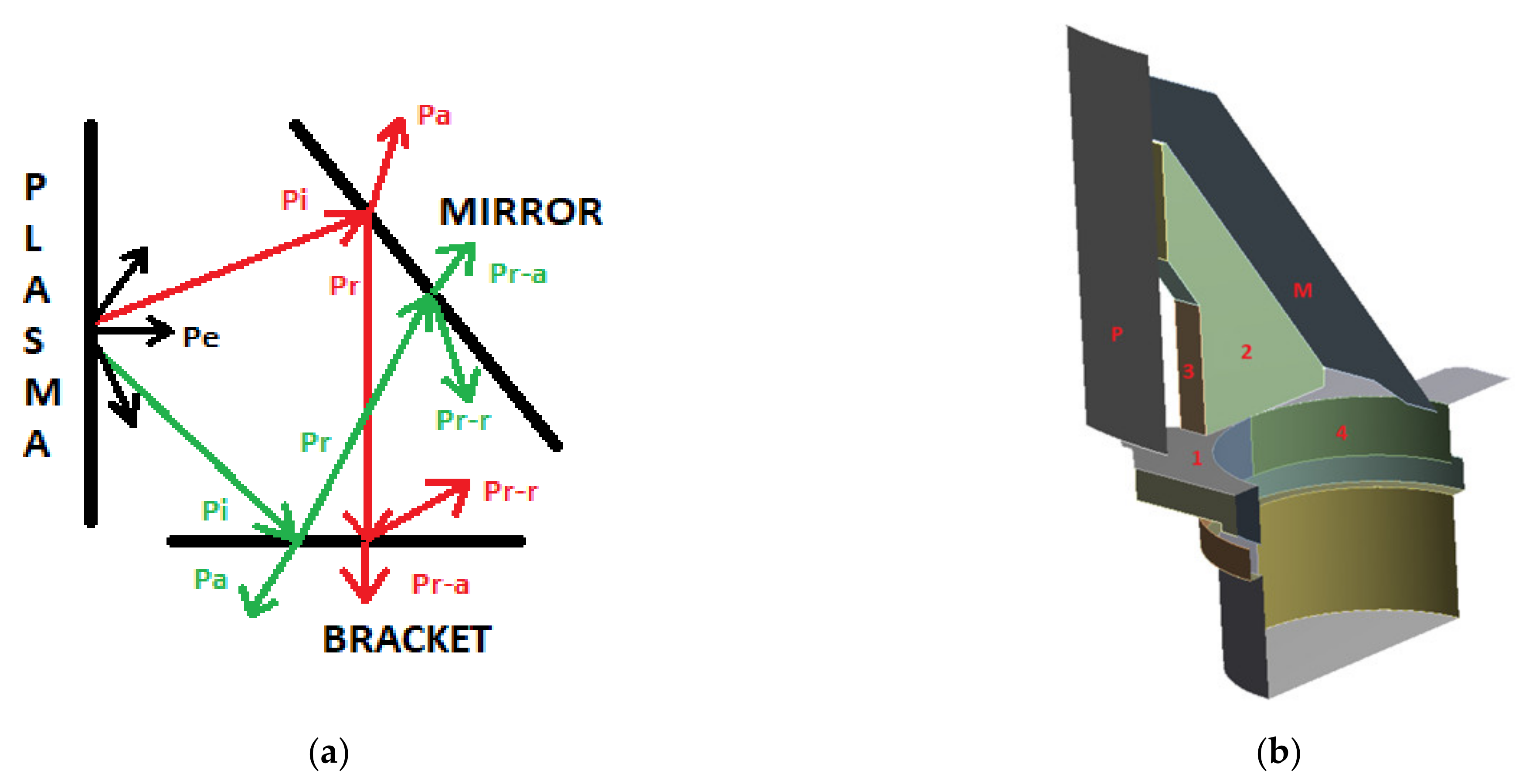
The incident heat flux on mirror and bracket faces can be calculated from the plasma radiation passing through the endoscope opening (set-up of
Figure 7).
Form factors of each face toward all others faces are defined prior to calculate the heat flux on these surfaces.
The incident heat flux on the mirror face is calculated considering the plasma emitted heat flux in addition to the reflected heat flux on all bracket surfaces.
In the same way, the incident heat flux on each bracket face is calculated considering the plasma emitted heat flux in addition to the reflected heat flux on mirror surface.
2.4. Modal Analysis
The carried out modal analysis allows obtaining the natural frequencies of the structure in a range from 0 to 660 Hz.
The assumptions are as follows:
The complete assembly is studied;
All four bases of the frame are fixed;
Some components are modeled by mass points, when necessary;
The frame is modeled with beam profiles.
The total mass of the structure is 1315.8 kg. The frame represents approximatively 85% of the total mass of the diagnostic.
2.5. Hydraulic Study
As the diagnostic is close to the plasma, the heat flux is not negligible and some components need to be actively cooled. The coolant available in the WEST tokamak is pressurized water at a temperature of 100 °C and a pressure of 36 bar.
Pressure drop is calculated in all components with the CFD software Ansys Fluent. k-ε is chosen as turbulence model because of its numerical stability, convergence and feedback. Conversely, heat transfer is neglected to calculate pressure drop.
For each component, the objects of the study are:
Evaluating pressure drop and making design improvements if necessary;
Studying the natural distribution of mass flow rate (in a global CFD simulation);
Describing the sub-components by plotting curves of the pressure drop (output parameter) depending on the velocity (input parameter).
This last point will allow for assessment of the relationship between pressure drop and velocity. At the end, diaphragms will be incorporated into the hydraulic system to properly distribute the water mass flow rate in all components.
The curve of the pressure drop depending on the velocity allows for understanding of the relation between these two variables with the equation:
where Δ
P represents the pressure drop from inlet to outlet of the component,
V indicates the inlet velocity, and
a and
b are respectively the inertial and viscous loss coefficient.
3. Results
3.1. Normal Operation Plasma Scenario—Global Analysis
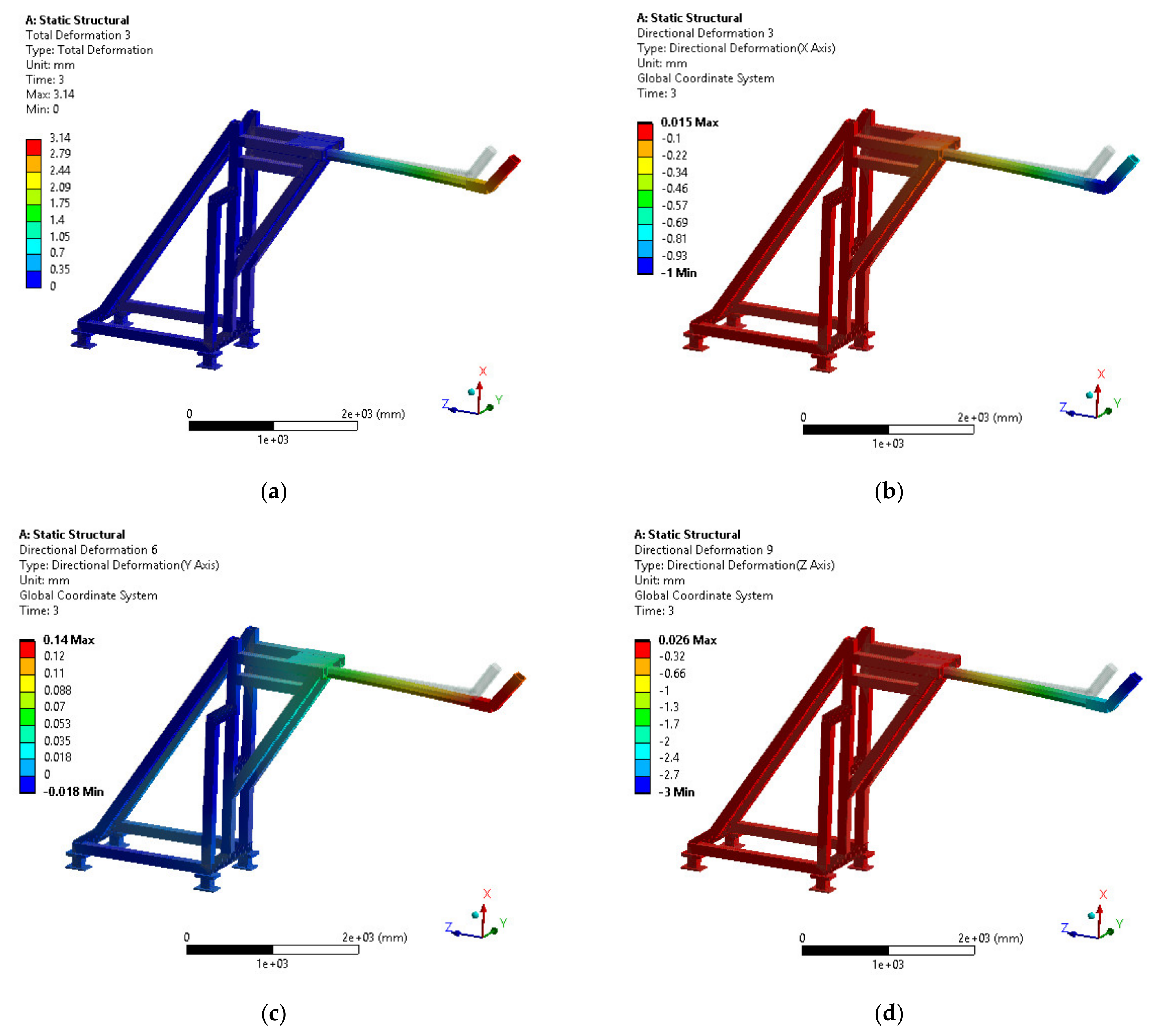
The results in terms of deformation (total and directional) of the structural steady-state analysis are illustrated in
Figure 8.
The thermal load due to plasma operation has the greatest impact on the total deformation. Because of cantilever beam, the Earth gravity leads to high vertical deformation. However, the obtained vertical deformation of 1 mm is lower than the maximal allowable value of 6 mm. The radial axis deformation shows the endoscope moving into the vacuum vessel for about 3 mm. This can be taken into consideration in the manufacturing and calibration process. Vacuum force and, mainly, the thermal load are responsible for this phenomenon.
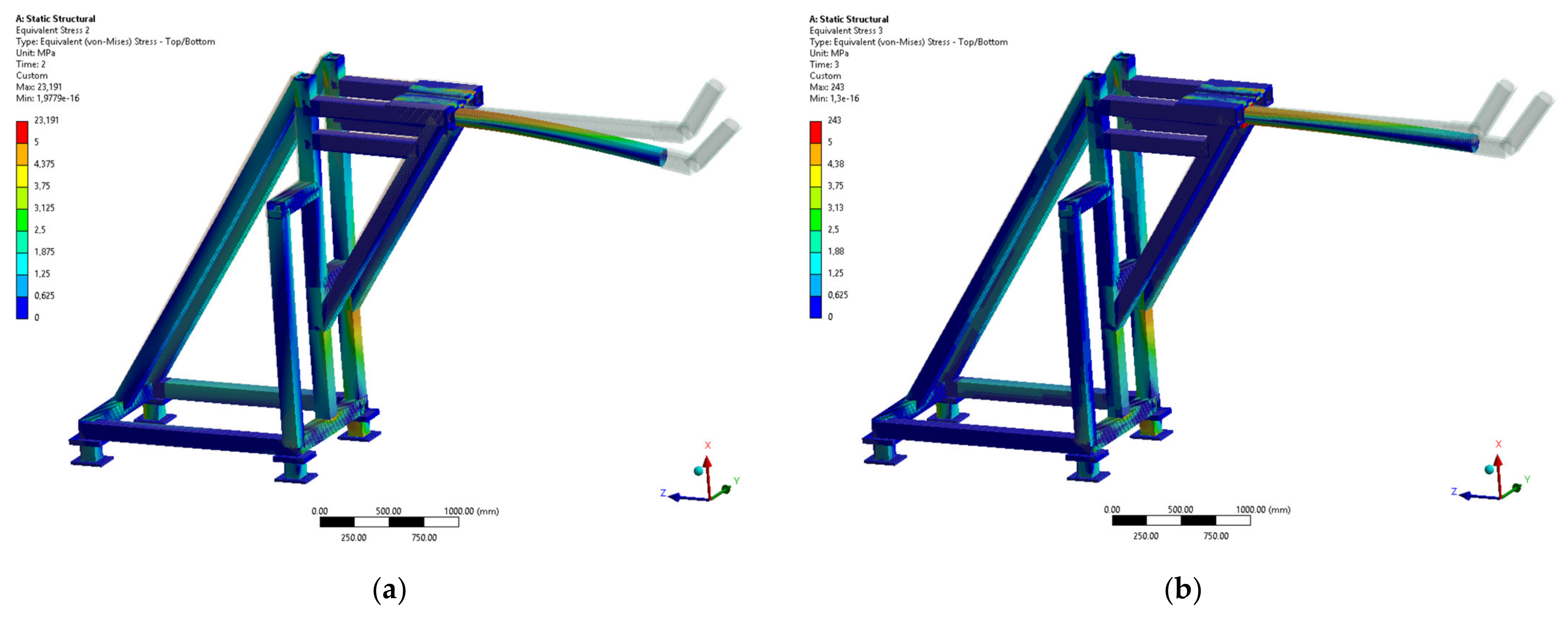
Figure 9 depicts the results in terms of equivalent von Mises stresses both for primary and secondary loads.
The primary stress is lower than the allowable value of 111 MPa given in §2.2.2. For the secondary load case, the maximal stress value of 243 MPa found between the cylinder of the endoscope and the frame is actually a numerical overstress and does not have physical meaning. Furthermore, this stress is still lower than the allowable value of 333 MPa.
3.2. Normal Operation Plasma Scenario—Local Analysis
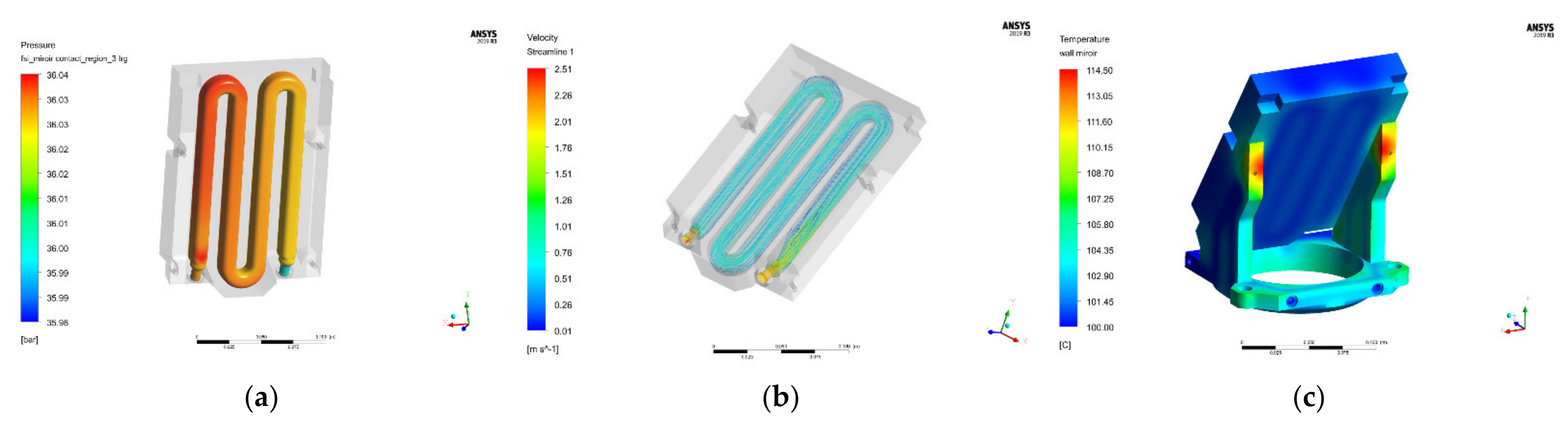
From the CFD simulation, the pressure profile in fluid bodies and the temperature profile in fluid and solid bodies are evaluated (
Figure 10).
The pressure profile and streamline of the bracket are shown in §3.4. Pressure drop in these components is low at the nominal mass flow rate. The maximal temperature is on the bracket’s body (114.5 °C), far from the water channels. The maximum temperature of the mirror is 106.6 °C (lower than the 200 °C limit).
The temperature profiles of both bodies are imported to a thermomechanical study, as well as the pressure at the fluid-structure interface in mirror and bracket bodies.
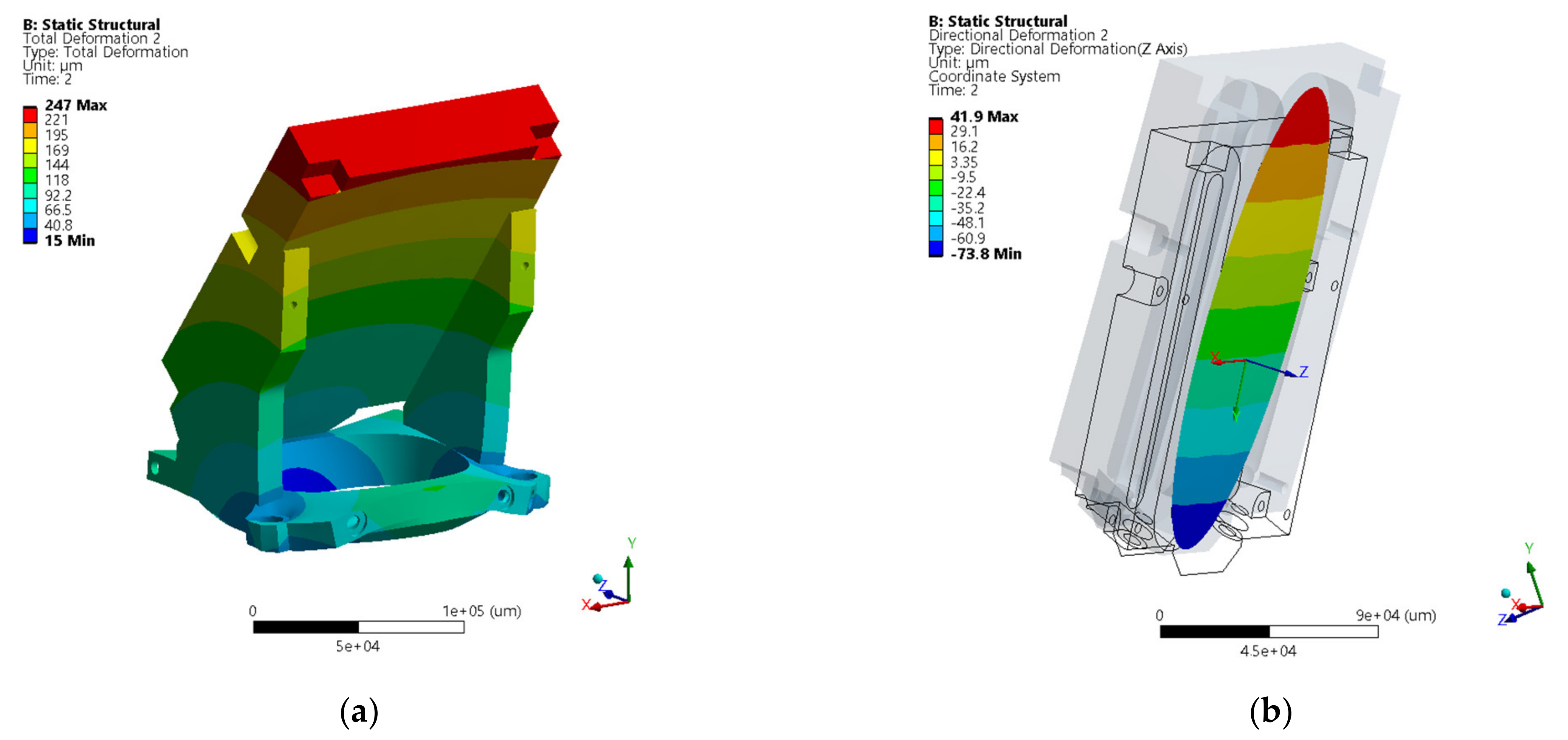
Figure 11 shows the total deformation for the mirror and the bracket, as well as the normal deformation of the mirror optical surface.
The normal displacement of the optical surface is 115.7 µm (coming from 41.9 + 73.8 µm,
Figure 11b). This displacement corresponds to a tilt of 3 arcmin (around the local relative
X-axis in the figure) that is lower than the allowable value of 6 arcmin. Conversely, a good hydraulic design of the channels has allowed for the obtainment of homogeneous pressure and body temperature distributions. This factor avoids the risk of deformation or tilt around other axes.
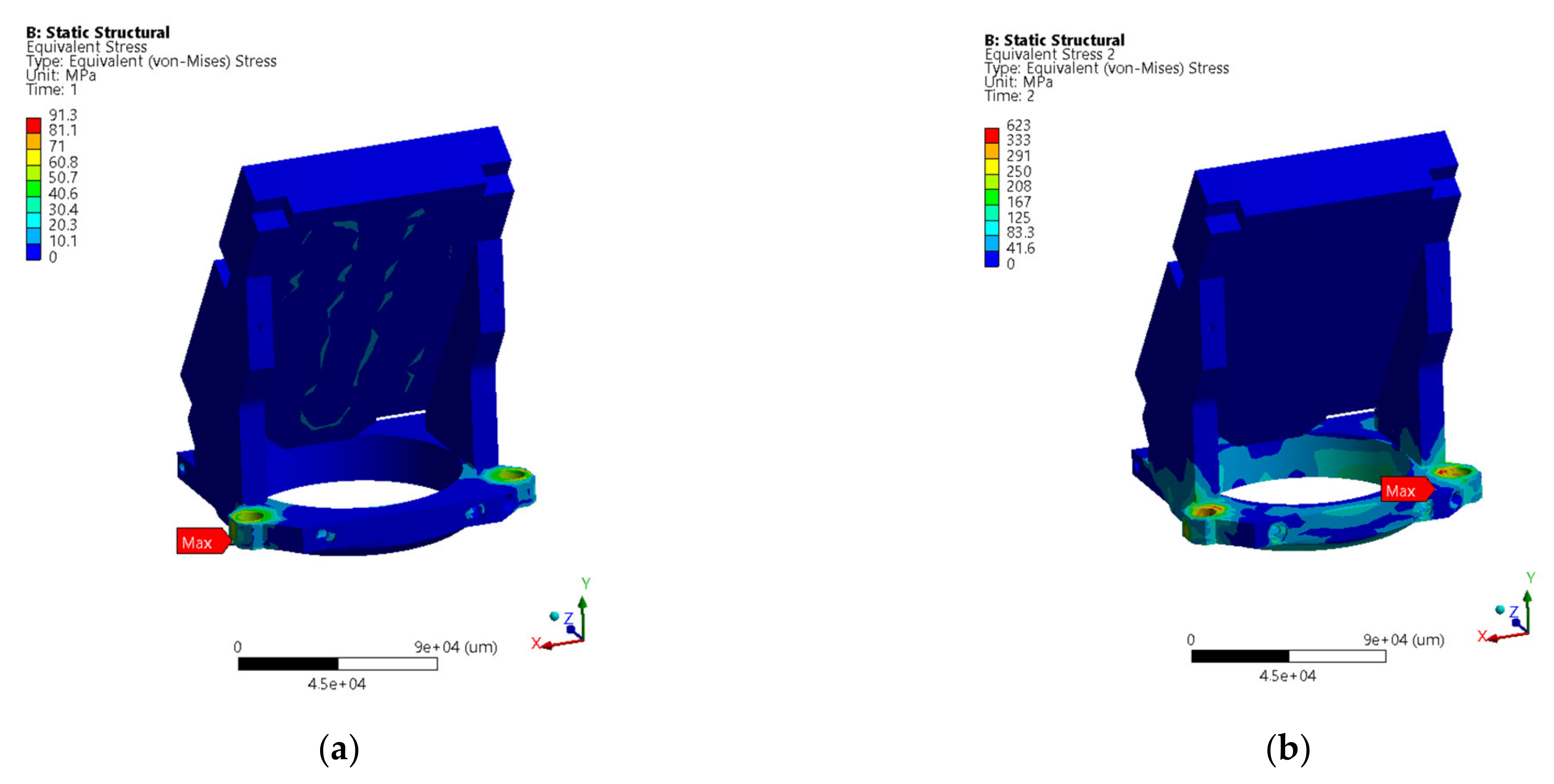
As shown in
Figure 12, the primary stress is lower than the allowable value of 111 MPa. The secondary stress is higher than the allowable value of 333 MPa.
However, the maximum stress is located in the screw holes and is caused by the boundary condition. A local yielding might occur in the worst case, but it would not affect the behavior of the system.
3.3. Modal Analysis
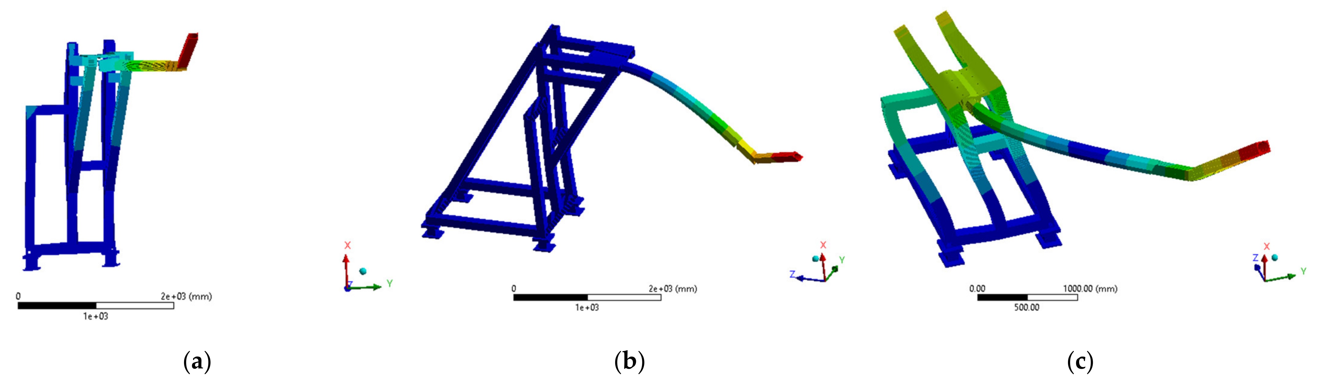
The natural frequencies of the structure from 0 to 660 Hz are shown in
Table 1, while the first three modes are represented in
Figure 13.
The first mode, at a frequency of 10.8 Hz, shows that the endoscope oscillates following the tangential axis. This is due to the non-symmetrical design of the frame in the ZX plane. The second mode at 15.4 Hz highlights the cantilever of the endoscope. The third mode at 20.9 Hz is a combination of both, a second order for the endoscope (vibration antinode visible at the middle) and a bending for the frame.
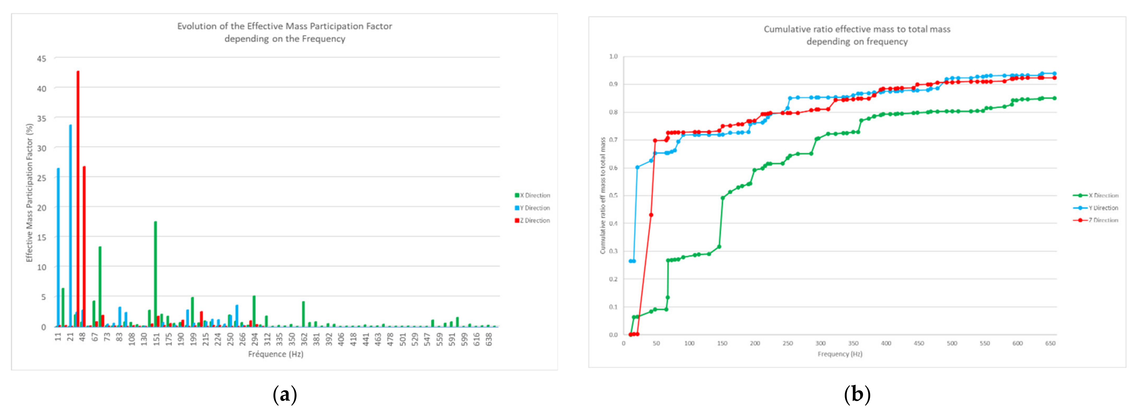
The effective mass participation factor (EMPF) represents the percentage of the system mass that participates in a particular mode in each direction. It provides a measurement of the energy contained within each resonant mode. A mode with a large EMPF is usually a significant contributor to the dynamic response of a system.
The effective mass-to-total-mass ratio is between the excited effective mass and the total mass of the body. By incrementing this value over the modes for each direction, the cumulative percentage of the excited mass was post-treated. Moreover, in order to actually validate the modal analysis, it is necessary to have at least 80% of participation mass in each direction.
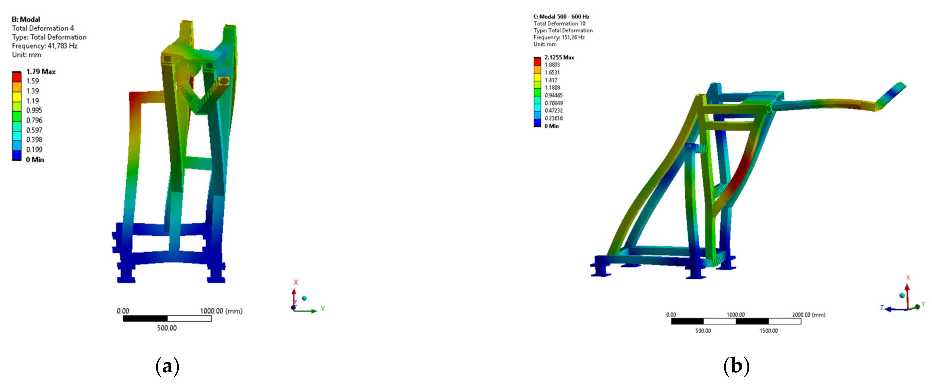
Figure 14a shows that the structure resonates at 41.8 and 47.9 Hz with a high mass participation factor in the radial axis. This result was generated by the flexibility of the rear part of the frame (given in
Figure 15a). In
Figure 14a, two modes appear at the frequency of 67.7 and 151.3 Hz in the vertical axis. These two modes are harmonics of the second mode at 15.4 Hz. In addition to the mass of the cantilever beam and the front of the endoscope, the mass of the frame also contributes to the resonance (
Figure 15b).
The natural frequencies of the structure around working frequencies of external components and plasma have negligible mass fraction participation (
Figure 14a,b).
3.4. Hydraulic Study
CFD simulations allow for the checking of the hydraulic design. The mass flow rate in each component depends on the incident plasma heat flux, and the aim is to ensure that the pressure drop of the total diagnostic is lower than 5.6 bar. Since the evaluated pressure drop was too high, the hydraulic design, especially of the bracket, had to be changed.
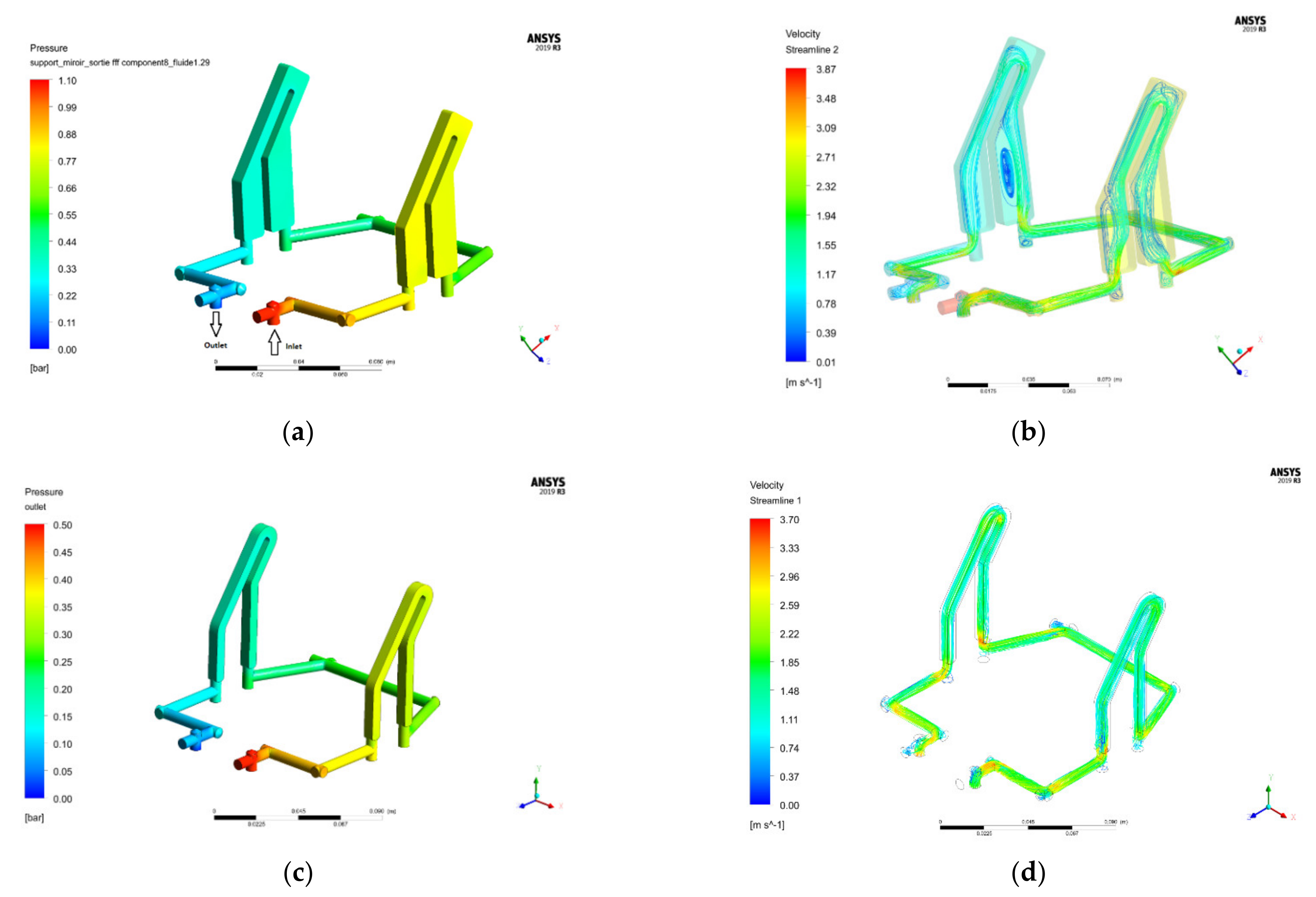
The pressure drop and velocity field into the bracket are given in
Figure 16.
In the first design, the pressure drop was above the prescribed limit (1.1 bar) at the velocity required to cool this component (2 m/s).
Figure 16b shows how the abrupt change of hydraulic section increased turbulence phenomena. The design optimization shown after reduced the pressure drop from 1.1 to 0.5 bar.
The curve of the pressure drop, depending on the velocity for the most important components, is plotted in
Figure 17.
For the mirror, the curve shows how the pressure drop value is still low when incrementing the velocity. This component will have the highest mass flow rate because of its plasma heat flux proximity. In addition, this relationship shows that friction losses are not negligible in front of regular pressure losses.
These equations will be essential during diaphragm characterization for flow balancing. These diaphragms will be designed using the formulas included in [
11].
4. Discussion
Global and local thermomechanical studies have demonstrated a foreseen correct functioning of the Thomson diagnostic during normal operation of WEST tokamak. The stress in the structure is lower than the allowable value. The deformation and the tilt of the mirror still ensure proper functioning for the optical system. The temperature of the mirror and its bracket is lower than 200 °C; thus, there will not be impact on the measurements due to interferences with infrared light.
In addition to the normal operation checking, the test operations have already been verified, while the electromagnetic disruption [
12] (vertical displacement Event) still has to be checked.
Problems due to vibration have not been identified. The lower natural frequencies of the structure are lower than 20 Hz. Some natural frequencies of the structure are near the working frequency of external perturbation assemblies. Nevertheless, the excited mass at these frequencies is low; hence, its effects can be neglected.
In order to increase the first mode of the structure, the frame should be reinforced to improve the mechanical strength. In the same way, the link between the frame and the endoscope could be reconsidered.
After some optimizations, pressure drop in all components was low. Moreover, since specific water mass flow rates need to be provided for each component, diaphragms will be designed and located in appropriate positions.
Author Contributions
Conceptualization, B.C., F.F., J.-M.V. and A.B.; methodology, B.C., N.L., T.B. and S.G.; software, B.C.; validation, N.L., T.B. and S.G.; resources, B.C. and A.B.; writing—original draft preparation, B.C.; writing—review and editing, S.G., N.L., T.B., G.C. and L.D.; supervision, L.D. and N.L.; project administration, G.C. All authors have read and agreed to the published version of the manuscript.
Funding
This research received no external funding.
Institutional Review Board Statement
Not applicable.
Informed Consent Statement
Not applicable.
Data Availability Statement
Not applicable.
Conflicts of Interest
The authors declare no conflict of interest.
References
- Bucalossi, J.; Missirlian, M.; Moreau, P.; Samaille, F.; Tsitrone, E.; Van Houtte, D.; Batal, T.; Bourdelle, C.; Chantant, M.; Corre, Y.; et al. The WEST project: Testing ITER divertor high heat flux component technology in a steady state tokamak environment. Fusion Eng. Des. 2014, 89, 907–912. [Google Scholar] [CrossRef]
- Colledani, G. The WEST Thomson Scattering System. HAL. 2020. Available online: https://hal.archives-ouvertes.fr/hal-02520947 (accessed on 17 January 2022).
- Bilkova, P. Design of New Thomson Scattering Diagnostic System on COMPASS Tokamak; Elsevier: Amsterdam, The Netherlands, 2010. [Google Scholar]
- Scannell, R.; Walsh, M.J.; Carolan, P.G.; Darke, A.C.; Dunstan, M.R.; Huxford, R.B.; McArdle, G.; Morgan, D.; Naylor, G.; O’Gorman, T.; et al. Design of a new Nd: YAG Thomson scattering system for MAST. Rev. Sci. Instrum. 2008, 79, 10E730. [Google Scholar] [CrossRef] [PubMed]
- NF EN 13445-2. Récipients Sous Pression non Soumis à La Flamme, Partie 2: Matériaux; AFNOR: Paris, France, 2002. [Google Scholar]
- NF EN 10028-7. Produits Plats en Aciers Pour Appareils à Pression, Partie 7: Aciers Inoxydables; AFNOR: Paris, France, 2000. [Google Scholar]
- NF EN 10088-1. Aciers Inoxydables, Partie 1: Liste des Aciers Inoxydables; AFNOR: Paris, France, 2014. [Google Scholar]
- Vives, S. Optical design and analysis of the Thomson Scattering optical head. Internal Communication, 2021. [Google Scholar]
- NF EN 13445-3. Récipients Sous Pression non Soumis à La Flamme, Partie 3: Conception; AFNOR: Paris, France, 2002. [Google Scholar]
- Aumenier, M.-H.; Moreau, P.; Bucalossi, J.; Firdaouss, M. Evaluation of radiative power loading on WEST metallic in-vessel components. In Proceedings of the EPs Conference on Plasma Diagnostics, Rome, Italy, 14–17 April 2015. [Google Scholar]
- Idel’Cik, I.E.; Meury, M. Mémento des Pertes de Charge; Eyrolles: Paris, France, 1986. [Google Scholar]
- Garitta, S. WEST sector EM analysis campaign. Internal Communication, 2020. [Google Scholar]
Figure 1.
(a) Laser path. (b) Sectional view of the WEST tokamak, including the Thomson scattering diagnostic.
Figure 1.
(a) Laser path. (b) Sectional view of the WEST tokamak, including the Thomson scattering diagnostic.
Figure 2.
Representation of the connection between the diagnostic and the vacuum vessel.
Figure 2.
Representation of the connection between the diagnostic and the vacuum vessel.
Figure 3.
Front of the endoscope.
Figure 3.
Front of the endoscope.
Figure 4.
Complete geometry of Thomson scattering diagnostic system.
Figure 4.
Complete geometry of Thomson scattering diagnostic system.
Figure 5.
Mirror and its bracket geometry.
Figure 5.
Mirror and its bracket geometry.
Figure 6.
(a) Head of endoscope: opened shutter configuration; (b) plasma heat flux.
Figure 6.
(a) Head of endoscope: opened shutter configuration; (b) plasma heat flux.
Figure 7.
(a) Heat balance on each face—Pe indicates the heat flux radiation emitted by the plasma. Pi, Pr and Pa represent respectively the incident, reflected and absorbed heat flux radiation on the component surface. (b) Symmetrical representation of the area of study—P represents the opening (hence the plasma), M indicates the mirror face and numbers 1 to 4 point to several surfaces of the bracket.
Figure 8.
(a) Total deformation (mm); (b) directional deformation in the vertical axis (mm); (c) directional deformation in the tangential vacuum vessel direction (mm); (d) directional deformation in the radial axis (mm).
Figure 8.
(a) Total deformation (mm); (b) directional deformation in the vertical axis (mm); (c) directional deformation in the tangential vacuum vessel direction (mm); (d) directional deformation in the radial axis (mm).
Figure 9.
(a) Equivalent von Mises stress for primary load. (b) Equivalent von Mises stress for secondary load.
Figure 9.
(a) Equivalent von Mises stress for primary load. (b) Equivalent von Mises stress for secondary load.
Figure 10.
(a) Pressure at fluid–structure interface in the mirror. (b) Streamline velocity inside fluid mirror body. (c) Temperature profile in solid bodies.
Figure 10.
(a) Pressure at fluid–structure interface in the mirror. (b) Streamline velocity inside fluid mirror body. (c) Temperature profile in solid bodies.
Figure 11.
(a) Total deformation of mirror and bracket; (b) normal deformation of the optical surface.
Figure 11.
(a) Total deformation of mirror and bracket; (b) normal deformation of the optical surface.
Figure 12.
(a) Equivalent von Mises stress for primary load. (b) Equivalent von Mises stress for secondary load.
Figure 12.
(a) Equivalent von Mises stress for primary load. (b) Equivalent von Mises stress for secondary load.
Figure 13.
(a) First mode representation—F1 = 10.8 Hz; (b) second mode representation—F2 = 15.4 Hz; (c) third mode representation—F3 = 20.9 Hz.
Figure 13.
(a) First mode representation—F1 = 10.8 Hz; (b) second mode representation—F2 = 15.4 Hz; (c) third mode representation—F3 = 20.9 Hz.
Figure 14.
(a) Evolution of the effective mass participation factor; (b) cumulative ratio effective mass-to-total-mass.
Figure 14.
(a) Evolution of the effective mass participation factor; (b) cumulative ratio effective mass-to-total-mass.
Figure 15.
(a) Fourth mode representation—F4 = 41.8 Hz; (b) Seventeenth mode representation—F17 = 151.3 Hz.
Figure 15.
(a) Fourth mode representation—F4 = 41.8 Hz; (b) Seventeenth mode representation—F17 = 151.3 Hz.
Figure 16.
CFD results for an inlet velocity of 2 m/s. (a) Pressure field of the first design. (b) Velocity streamline of the first design. (c) Pressure field of the new design. (d) Velocity streamline of the new design.
Figure 16.
CFD results for an inlet velocity of 2 m/s. (a) Pressure field of the first design. (b) Velocity streamline of the first design. (c) Pressure field of the new design. (d) Velocity streamline of the new design.
Figure 17.
Pressure drop depending on velocity.
Figure 17.
Pressure drop depending on velocity.
Table 1.
Natural frequencies of the global structure.
Table 1.
Natural frequencies of the global structure.
| Mode | Frequency (Hz) | Mode | Frequency (Hz) | Mode | Frequency (Hz) |
|---|
| 1 | 10.8 | 25 | 215.4 | 49 | 417.5 |
| 2 | 15.4 | 26 | 219.7 | 50 | 423.7 |
| 3 | 20.9 | 27 | 223.6 | 51 | 441.4 |
| 4 | 41.8 | 28 | 242.1 | 52 | 447.6 |
| 5 | 47.9 | 29 | 249.7 | 53 | 463.5 |
| 6 | 65.3 | 30 | 253.5 | 54 | 467.9 |
| 7 | 67.1 | 31 | 265.6 | 55 | 478.3 |
| 8 | 67.7 | 32 | 286.0 | 56 | 491.9 |
| 9 | 73.3 | 33 | 293.9 | 57 | 500.9 |
| 10 | 77.9 | 34 | 296.5 | 58 | 509.8 |
| 11 | 83.5 | 35 | 311.5 | 59 | 529.1 |
| 12 | 90.9 | 36 | 322.8 | 60 | 539.0 |
| 13 | 108.4 | 37 | 334.9 | 61 | 547.3 |
| 14 | 114.5 | 38 | 340.3 | 62 | 552.6 |
| 15 | 129.9 | 39 | 349.5 | 63 | 559.2 |
| 16 | 145.7 | 40 | 357.1 | 64 | 580.1 |
| 17 | 151.3 | 41 | 362.1 | 65 | 591.4 |
| 18 | 162.4 | 42 | 373.1 | 66 | 592.8 |
| 19 | 174.8 | 43 | 381.3 | 67 | 598.6 |
| 20 | 180.8 | 44 | 382.0 | 68 | 607.1 |
| 21 | 190.0 | 45 | 391.5 | 69 | 615.8 |
| 22 | 193.0 | 46 | 395.6 | 70 | 633.6 |
| 23 | 199.5 | 47 | 406.4 | 71 | 637.9 |
| 24 | 211.5 | 48 | 414.0 | 72 | 656.4 |
| Publisher’s Note: MDPI stays neutral with regard to jurisdictional claims in published maps and institutional affiliations. |
© 2022 by the authors. Licensee MDPI, Basel, Switzerland. This article is an open access article distributed under the terms and conditions of the Creative Commons Attribution (CC BY) license (https://creativecommons.org/licenses/by/4.0/).


 ,
, 


