Article

Analysis of the Thermo-Mechanical Behaviour of the EU DEMO Water-Cooled Lithium Lead Central Outboard Blanket Segment under an Optimized Thermal Field

by
Ilenia Catanzaro
*,
Gaetano Bongiovì
and
Pietro Alessandro Di Maio
Department of Engineering, University of Palermo, 90128 Palermo, Italy
*
Author to whom correspondence should be addressed.
Appl. Sci. 2022, 12(3), 1356; https://doi.org/10.3390/app12031356
Submission received: 1 December 2021 / Revised: 13 January 2022 / Accepted: 25 January 2022 / Published: 27 January 2022
(This article belongs to the Special Issue Structural and Thermo-Mechanical Analyses in Nuclear Fusion Reactors)

Abstract

:
Within the framework of the EUROfusion research activities on the DEMO Water-Cooled Lithium Lead (WCLL) Breeding Blanket (BB) design, a research study was performed to preliminarily optimize, from the thermal point of view, the WCLL Central Outboard Blanket (COB) segment in order to investigate its structural behaviour under a realistic thermal field. In particular, a study of thermal analyses was performed to optimize the Double Walled Tubes and Segment Box cooling channels’ geometric configurations along the poloidal extension of the WCLL COB segment, in order to obtain a spatial temperature distribution fulfilling the thermal design requirement. Then, the thermo-mechanical analysis of the WCLL COB segment under Normal Operation (NO, representing nominal conditions), Upper Vertical Displacements Event (UVDE, representing a plasma disruption event) and Over-Pressurization (OP, representing an in-box loss of coolant accident) scenarios were carried out, assuming the previously obtained thermal field, to realistically predict displacement and stress fields. Finally, a stress linearization procedure allowed comparing the stress values obtained in some critical regions of the structure with the criteria prescribed by the reference design standard RCC-MRx. A theoretical–numerical approach based on the Finite Element Method (FEM) was followed using the commercial code Abaqus v. 6.14.

1. Introduction

Within the framework of the conceptual design of the EU-DEMO Breeding Blanket (BB) [1,2], the University of Palermo is involved in the design of the Water-Cooled Lithium Lead (WCLL) BB foreseen for the European DEMO fusion reactor. One of the main objectives of the research activity is the development of a geometric layout for the WCLL Central Outboard Blanket (COB) segment robust enough to fulfil all the prescribed design requirements. To this purpose, the assessment of its thermo-mechanical behaviour under different loading conditions plays a key role and, in this regard, the availability of a realistic and detailed thermal field for the whole WCLL COB segment is pivotal. Nevertheless, the WCLL COB design presented at the end of the pre-conceptual phase [3] was not mature enough to allow reliable thermal–hydraulic assessments for the prediction of its thermal field. In any case, such an analysis would require a huge modelling effort, followed by a tremendous computational burden, which would entail the adoption of strong assumptions leading to a certain margin of uncertainties in the results [4]. Hence, an alternative procedure was developed [5] and applied in this study in order to predict a reliable 3D thermal field for the WCLL COB without performing its full thermal–hydraulic analysis, taking into account the radial and poloidal dependence of the thermal loads (namely, nuclear heating and heat flux on the FW surface).
Afterwards, once the 3D thermal field of the WCLL COB segment was predicted, its structural behaviour was evaluated under different steady-state loading scenarios. First, the Normal Operation (NO) scenario, representing the normal operating conditions and thus falling under service Level A of the RCC-MRx [6] structural design code, was taken into account. Secondly, proper accidental loading scenarios were set-up, derived from two off-normal reference events: the Upper Vertical Displacements Event (UVDE) and the in-box Loss of Coolant Accident (LOCA). The UVDE is an abnormal event reproducing a plasma disruption due to an uncontrolled vertical motion of the plasma volume, classified as Level C. In contrast, the in-box LOCA is the design-driving accident for the BB and therefore it is classified as Level D in the RCC-MRx design code. Its associated loading conditions form the Over-Pressurization (OP) steady state loading scenario. The thermo-mechanical behaviour of the whole WCLL COB segment was therefore assessed in terms of displacement and equivalent von Mises stress fields. Moreover, a stress linearization procedure was performed within some critical regions, in order to evaluate the stress level by means of the design rules prescribed by the French nuclear code RCC-MRx, currently the primary reference for the DEMO reactor.
A theoretical–numerical approach based on the Finite Element Method (FEM) was followed. The commercial code Abaqus v. 6.14 [7], considered as one of the reference FEM codes by the international scientific community involved in the nuclear fusion research, was utilized. The obtained results are presented herein and critically discussed. To this end, the adopted methodology and the structure of the paper are reported in the Section 2.

2. The Adopted Methodology

As stated in the previous section, the WCLL COB design passed through the DEMO pre-conceptual gate review was not detailed enough to allow reliable thermal–hydraulic analysis for the detailed calculation of its thermal field. At the same time, the availability of a reliable and detailed 3D temperature spatial distribution for the whole segment is crucial for the assessment of its thermomechanical performances in different loading scenarios. Hence, in this study, an alternative procedure was applied to get a reliable estimation of the thermal field arising within the WCLL COB segment without performing its whole thermal–hydraulic assessment.
To this purpose, it has to be observed that each BB segment could be ideally subdivided into 7 poloidal regions [3,8], each characterized by a certain set of distributed thermal loads (namely, plasma heat flux, nuclear heating and decay-heat power density) representative of the operating conditions of the considered region (Figure 1). In this study, the equatorial radial-toroidal elementary cell of each of the 7 COB poloidal regions (as depicted, as an example, for the O5 region in Figure 1) was assessed from the thermal point of view (Section 3.1), taking into account the 3D nature of the pertinent thermal loads and the reference geometric layout, described below. To this purpose, considering the suggested Eurofer maximum temperature limit equal to 550 °C within the structural components [3], it was found that a thermal optimization of the WCLL COB segment’s cooling layout (namely first wall channels and breeding zone cooling tubes) was necessary in order to obtain, for each of the 7 equatorial cells assessed, a thermal field fulfilling the abovementioned requirement minimizing the number of tubes.
Hence, alternative geometric layouts were conceived and assessed assuming, for each of the 7 poloidal regions, the corresponding set of thermal loads (Section 3.2). Once an optimized geometric layout for the cooling system and the pertinent thermal field fulfilling the design requirement was obtained for each of the 7 equatorial cells assessed, an interpolation procedure was performed in order to carry out 7 different sets of interpolating functions of the radial and toroidal variable capable of reproducing the calculated thermal fields with a high level of confidence. Then, the found sets of interpolating functions were applied to the 7 poloidal regions (namely to the whole O1, O2, …, O7 region) so as to reproduce, on the whole COB segment, a detailed 3D thermal field originated by the radial–poloidal dependent thermal loads, fulfilling the prescribed design thermal requirement.
At this point, the structural assessment (Section 4) of the whole WCLL COB under the obtained optimized 3D thermal field was performed, under the nominal and accidental steady state loading scenarios described below. The obtained results were used to assess the displacement and von Mises-equivalent stress fields and to perform a stress linearization procedure in some critical areas, so as to verify the fulfilment of the structural design criteria, namely, the criteria prescribed by the RCC-MRx structural design code.

3. Thermal Analysis of the WCLL COB Segment

In order to assess the thermo-mechanical performances of the WCLL COB segment, the first step was the determination of a thermal field for the whole segment. To this end, fulfilling the thermal design requirement on the maximum Eurofer temperature [3] necessitated optimizing the WCLL COB segment’s cooling scheme. In this framework, the first step was the thermal analysis of the reference layout of the equatorial radial-toroidal elementary cell of each of the 7 COB poloidal regions (from O1 to O7, Figure 1). Afterwards, the thermal optimization of those regions not fulfilling the prescribed requirement was performed with the aim of obtaining a thermal field characterized by the maximum Eurofer temperature within structural components lower than 550 °C [3].

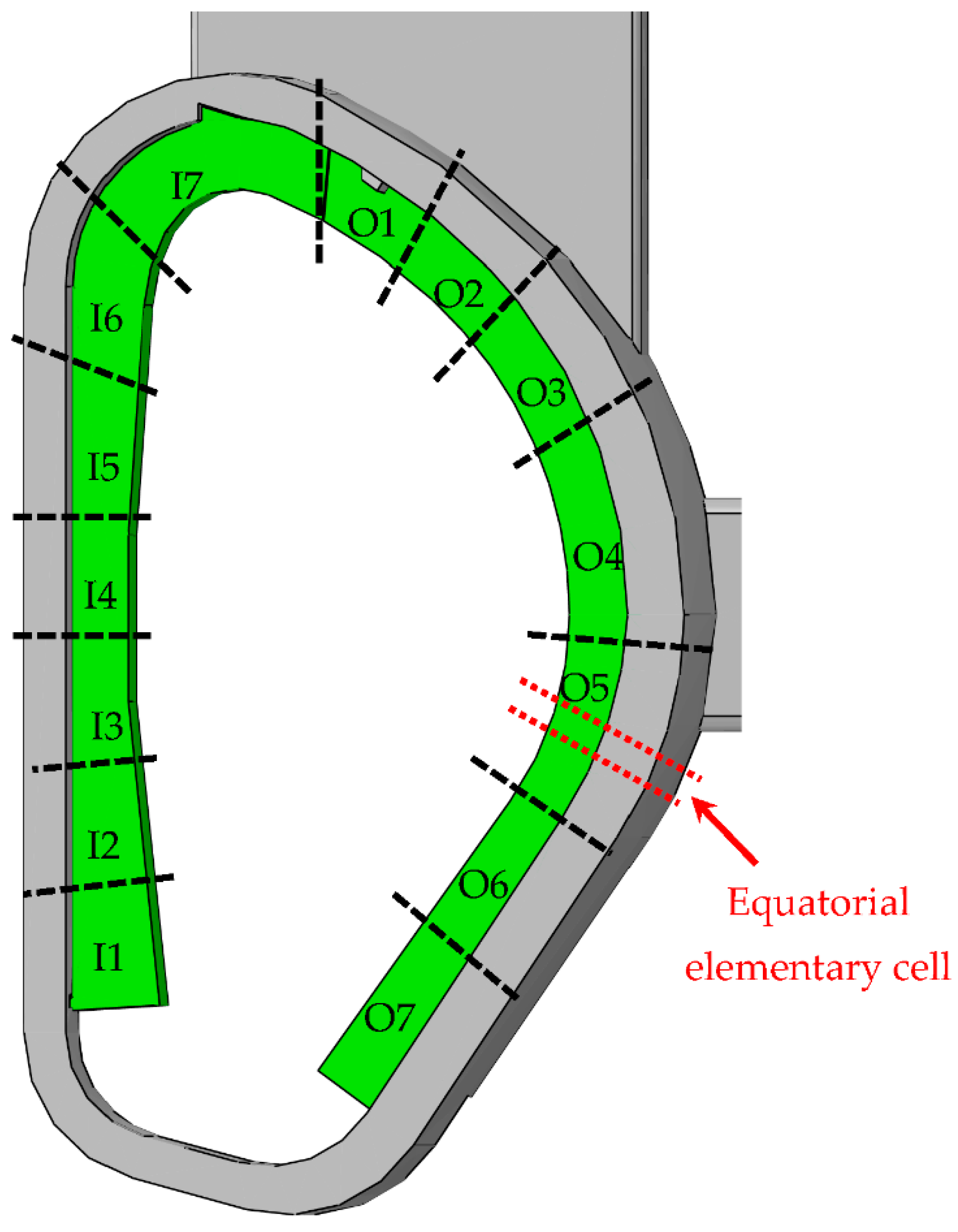
3.1. Thermal Analysis of the Equatorial Radial-Toroidal Cell of Each of the 7 COB Poloidal Regions

The thermal analysis of the reference layout of the equatorial radial-toroidal elementary cell of each of the 7 COB poloidal regions was performed under the steady state normal operation loading conditions foreseen for the WCLL COB.

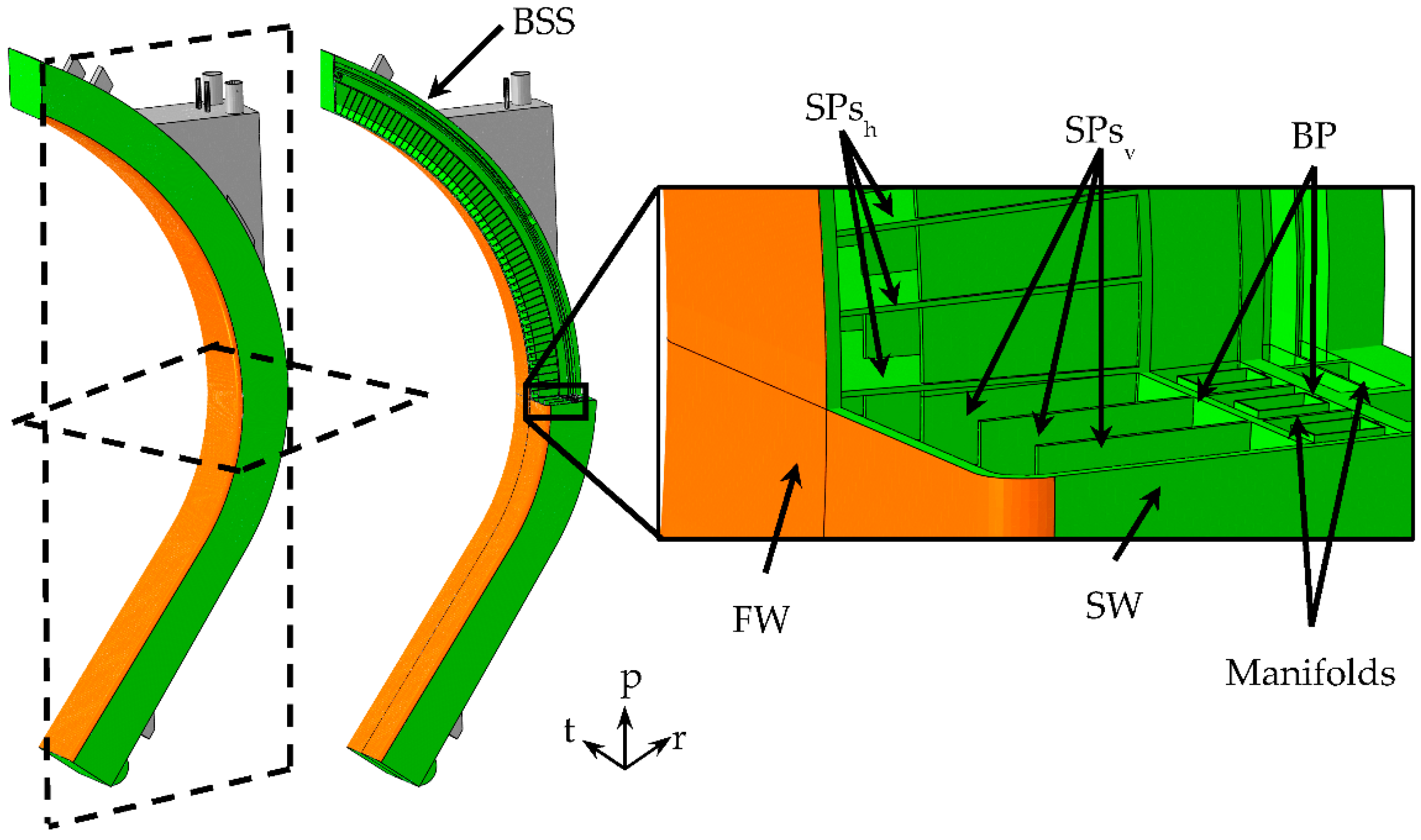
3.1.1. The Reference Geometric Layout

In accordance with the Single Module Segmentation (SMS) concept, the WCLL COB Segment is composed of a single elementary cell, identified by two horizontal Stiffening Plates (SPs), that repeats along the poloidal direction from one cap to another that vertically closes the segment. The structure, depicted in Figure 2, is mainly characterized by the Segment Box (SB), divisible into the First Wall (FW), with the 2 mm-thick W-armour (coloured in orange in Figure 2), and the Side Walls (SWs) that laterally close the SB. Moreover, the structure is closed in the back by the complex of Back Plate (BP), water and breeder manifolds and the Back Supporting Structure (BSS), and connected to the attachment system (coloured in grey in Figure 2), aimed to mechanically connect the Segment to the Vacuum Vessel (VV). The breeder flows inside the box, in the region called Breeder Zone (BZ) [3], which is reinforced by means of the SPs. In particular, the SPs grid is composed of horizontal (or toroidal-radial) and vertical (or poloidal-radial) SPs, with a thickness equal to 10 and 12 mm, respectively. A bundle of 22 cooling tubes per cell (Figure 3), Double Walled Tubes (DWTs), immersed in the PbLi, has the role of cooling the BZ; in contrast, the FW-SW-FW region is cooled by means of 7 × 7 m2 cooling channels located into the SB.
In order to observe the different thermal loads characterizing the poloidal extension of the segment, the number of cooling channels per cell varies along the COB segment [3], following the aforementioned poloidal segmentation. In particular, four channels per cell are foreseen for each poloidal region with exception of O7 region in which six channels are foreseen. Instead, only one DWTs configuration was preliminarily selected for all the elementary cells along the segment. In particular, the chosen DWTs layout, named v06b as reported in [3], consisted of 22 C-shaped double-walled tubes, with a hydraulic diameter of 8 mm and an external diameter equal to 13.5 mm, each with different position and radius. In Figure 3 the DWTs layout in an elementary cell (namely, an equatorial radial-toroidal cell) and the water path inside them (in which red arrows indicate the inlet and green the outlet), with the BZ recirculation scheme (highlighted in orange), is reported.
In the present work, two realistic 3D geometric models of a couple of elementary cells (Figure 4), equipped with four and six cooling channels, respectively, and the WCLL v06b DWTs layout, representing a portion of the whole COB segment, were set up in order to realistically simulate its thermal behaviour. Given that the reference DWTs layout is the same along the whole segment, the geometric model envisaging four FW channels represents the equatorial radial-toroidal cell of regions from O1 to O6, whereas the model with an FW equipped with 6 cooling channels represents the equatorial elementary cell of the O7 poloidal region.
Two detailed FEM models have been set-up, each one composed of ~13M nodes connected in ~5M linear hexahedral and tetrahedral elements, including the Eurofer structure, tungsten layer, DWTs, breeder and water coolant flowing inside FW channels and DWTs.

3.1.2. Loads and Boundary Conditions
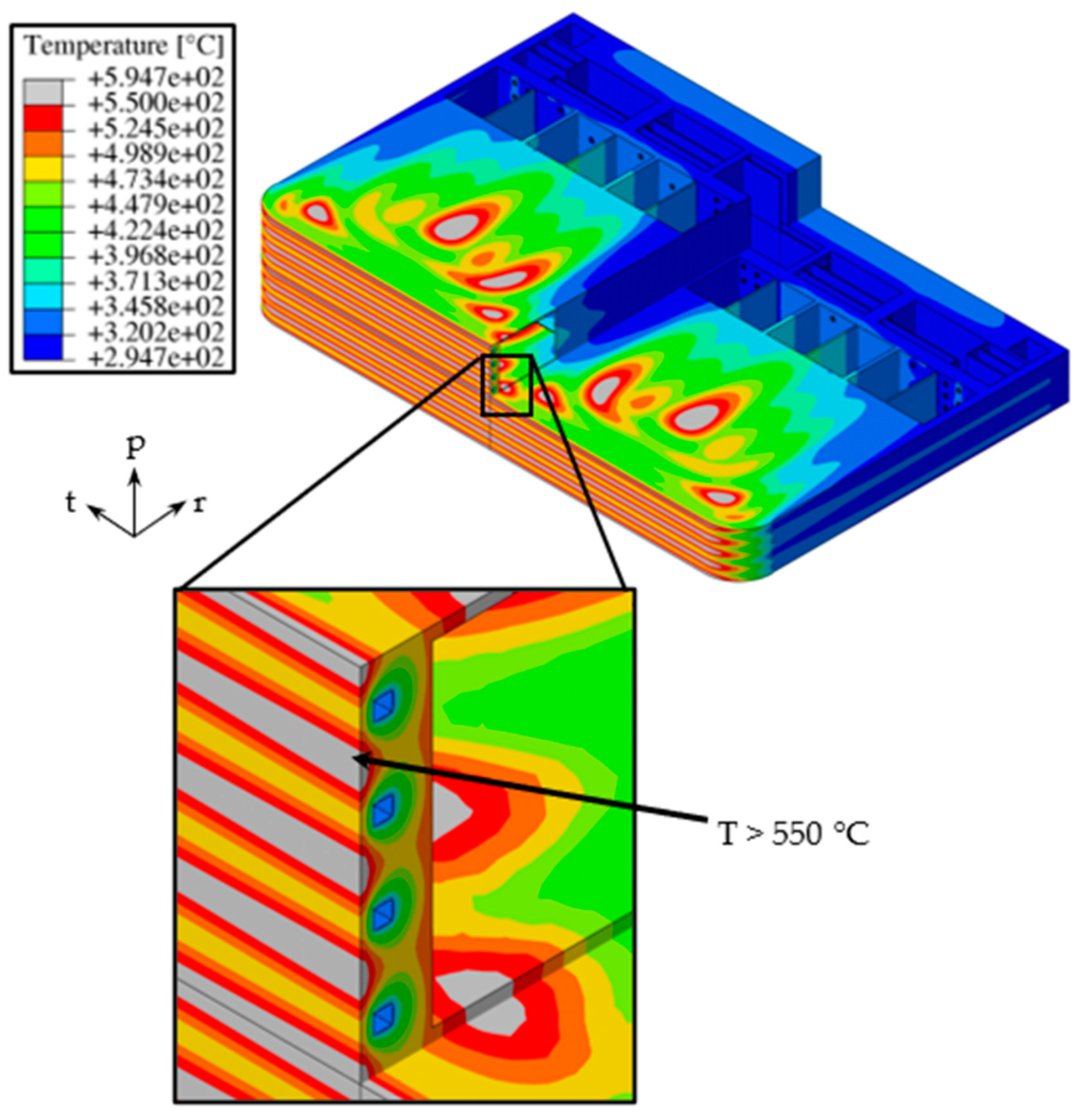
In order to perform the thermal analysis, a set of loads and boundary conditions, pertinent to the Normal Operation steady state loading scenario, was considered for each model taken into account.
The temperature-dependent properties of materials were taken into account. In particular, for Eurofer, Pb-15.7Li and Tungsten, the physical properties were drawn from [9,10,11].
A non-uniform value of heat flux (Φ), due to particles and radiation arising from plasma, for each of the COB poloidal regions was imposed on the straight and bent FW plasma facing surface. The selected heat flux values [8], assumed at the end of flat-top, are reported in Table 1. In particular, the values reported in Table 1 were applied to the straight FW surface. In contrast, for the bent FW surfaces, a decreasing value according to a cosine-dependent law was assumed, considering the values reported in Table 1 as maximum ones:
ΦFWbend = ΦFW∙cosα
where ΦFWbend is the value imposed to the bend FW surface, ΦFW the values reported in Table 1 as maximum ones and α varies between 0, corresponding to the start of the bent region, and π/2, to the SW.
Moreover, a spatial distribution of volumetric density of nuclear-deposited heat power, derived from neutron transport analysis [3], was imposed upon each FEM model to simulate the distributed power deposition as a result of the neutrons, gamma photons and nuclei interactions. Moreover, differently from the previous thermal analysis carried out, the contribution of the decay heat, caused by the activated materials, was also taken into account [12]. In particular, the decay heat power spatial distribution calculated at the shut-down was assumed for the normal operation scenario, as it contributes to heating the structure.
Since the spatial distributions of nuclear power and decay heat were calculated only for the O4 region, the analogous spatial distributions for the other six poloidal regions were obtained using the ratio between the Neutron Wall Loadings (NWLs) in the i-th region and that in the O4 region as a scaling factor. The adopted NWLs average values for each COB region [3] are reported in Table 1.
Moreover, in order to simulate the thermal contact of the PbLi with the SB and DWTs breeder-wetted surfaces, a pure diffusive heat transfer contact with a conservative value of thermal conductance equal to 100 [kW/m2·°C] was assumed. The breeder, since it flows very slowly, due to the action of buoyancy and magneto-hydrodynamics forces, can in fact be considered as stagnant. Then, the DWTs and the SB structure are considered as a continuum concerning the thermomechanical behaviour.
Finally, a forced convective heat transfer between coolant and water-wetted surfaces adopting a proper thermal contact was considered. In particular, a countercurrent flow path was imposed for the FW-SW cooling water. Concerning the DWTs cooling water, the path shown in Figure 3 was simulated and the recirculation system was properly modelled. To reproduce the DWTs water path, the tubes were divided into two groups: the first, in which the water enters at 295 °C, including 14 tubes; and the second, where the recirculation takes place, including 8 tubes. In order to correctly simulate the recirculation system, the average water outlet temperature, namely mixing temperature, of the first group was calculated and set as the water inlet temperature of the second group of tubes, by means of a proper Abaqus procedure.
A first attempt value of mass flow rate was selected for each group of DWTs and channel, and a related heat transfer coefficient, calculated using the Dittus & Boelter (D&B) correlation [13], was considered. In particular, an inlet temperature of 295 °C and a water temperature difference (ΔT) between inlet and outlet equal to 33 °C were utilized for the calculation. So, the heat transfer coefficients (HTCs) and the mass flow rates values needed to ensure the selected ΔT were calculated by means of an iterative procedure [14]. Lastly, adopting a “frozen field” calculation approach, it was possible to calculate the water bulk temperature along each channel/tube abscissa. In particular, the adopted iterative procedure consists of imposing the bulk temperature and mass flow rate (i.e., mass flow per unit area) at the inlet of each of the cooling tubes or channels together with the “first attempt” (i.e., calculated using the D&B correlation) HTC. The latter does not change during the current iteration. Hence, such an approach allows calculating the bulk temperature along the flow direction and using it for the imposition of the convective heat transfer condition. The thermal analysis has been iterated so as to obtain an HTC value able to produce a thermal rise between water inlet and outlet of ~33 °C. In Table 2 the HTC values adopted for each poloidal region in the last iteration for the complex of cooling channels and DWTs, where HTCCC, HTCDWTs and HTCDWTs,rec indicate the HTC values used for the cooling channels, first group of DWTs and recirculation DWTs, respectively, are reported.

3.1.3. Results

A steady-state thermal analysis was performed for the equatorial cells of each of the 7 COB poloidal regions with the aim of investigating their thermal behaviour under the loads and boundary conditions they undergo. For the sake of brevity, the maximum temperature predicted in each region is reported in Table 3, where the temperatures exceeding the suggested limit value of 550 °C are reported in red. Looking at the temperature values reached on SPs and FW, as the baffle plates do not play a structural role, only O1 and O7 regions did not overtake the Eurofer structural material limit temperature, set to 550 °C, whereas all the others exceeded this value. Hence, for the latter regions, an optimization of the DWTs layout was necessary. Moreover, looking at the results reported in Table 3, the O6 region showed a temperature higher than the temperature limit on the FW too. This result suggests that this poloidal region must be equipped with 6 channels, as in O7. Hence, as to O6 region, a further optimization of the FW channels was necessary.
As an example, the thermal field obtained within the structural material of the O4 region, corresponding to the equatorial region of the whole COB segment, is depicted in Figure 5, whereas in Figure 6 the spatial temperature distribution within Eurofer of the O6 equatorial cells is depicted.

3.2. WCLL COB Thermal Optimization and Determination of Its Thermal Field

The results obtained from the thermal analysis of the reference geometric layout of the equatorial elementary cell of each WCLL COB poloidal region allow concluding that, as to the O2, O3, O4 and O5 regions, a thermal optimization of the DWTs layout is necessary to allow fulfilling the requirement on the maximum Eurofer temperature. In addition, for the O6 region, the FW channels should also be optimized, since critical temperature values are predicted within both FW and SPs. Lastly, once the optimized thermal field for each of the 7 poloidal regions is obtained, a thermal field for the whole WCLL COB segment can be derived.

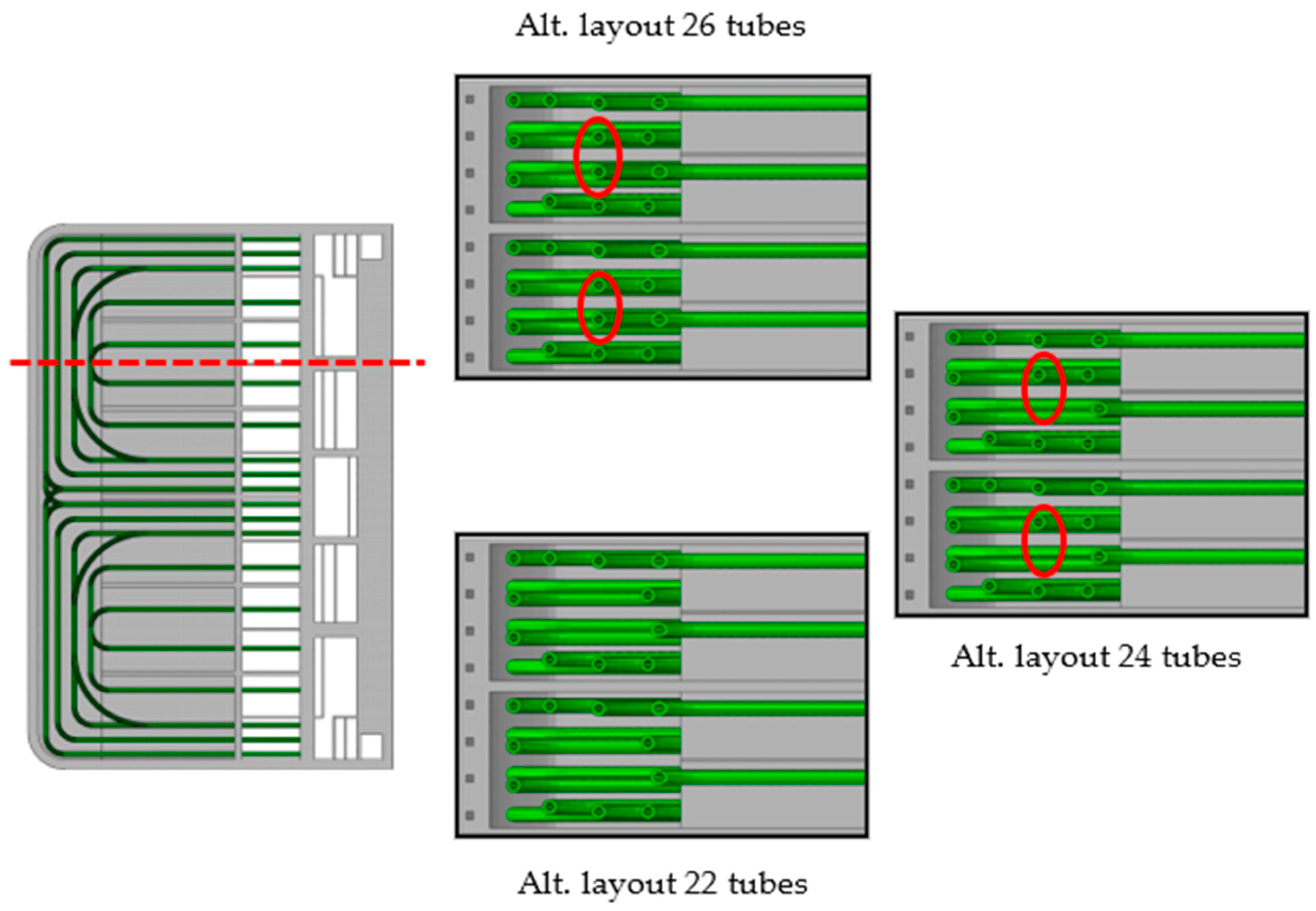
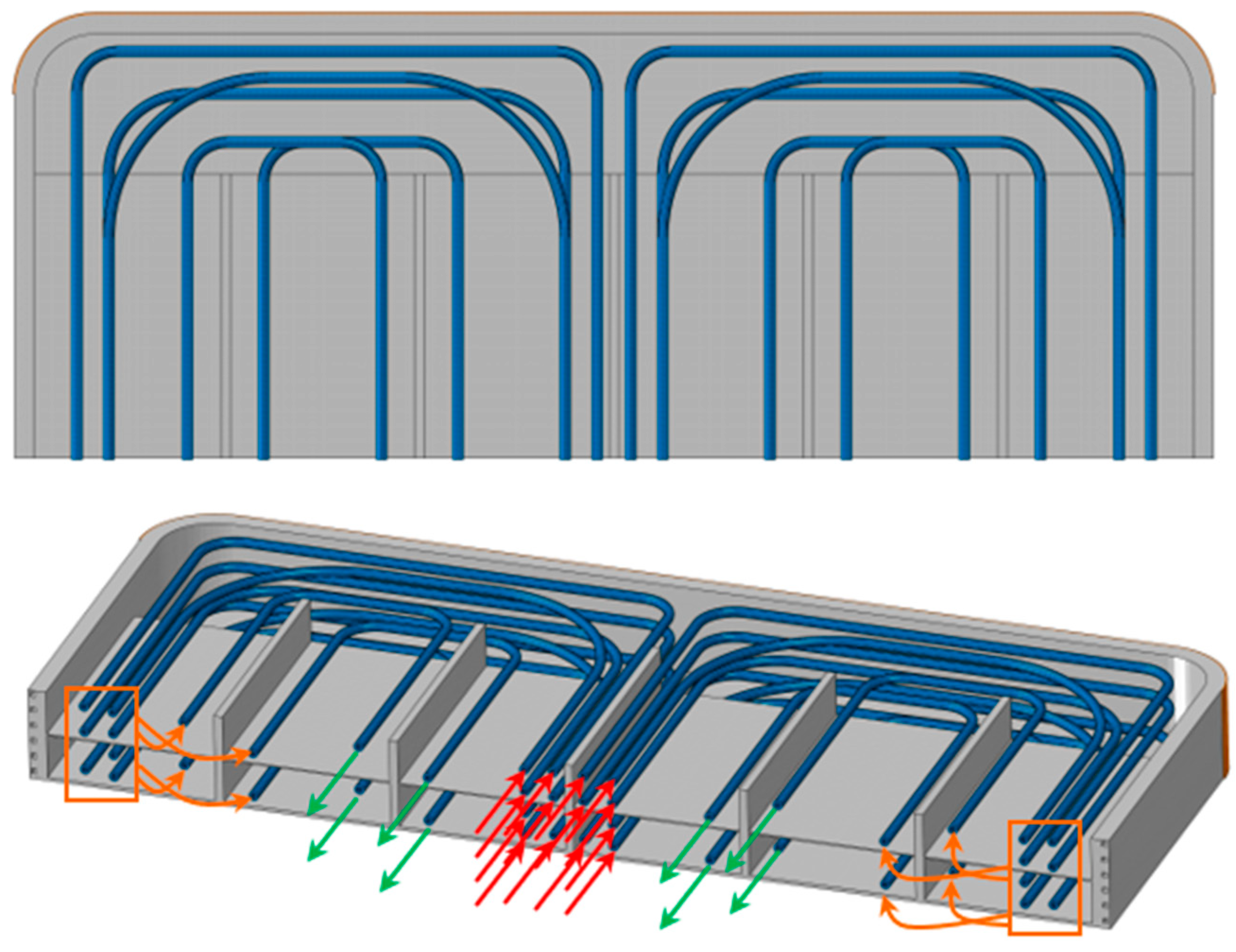
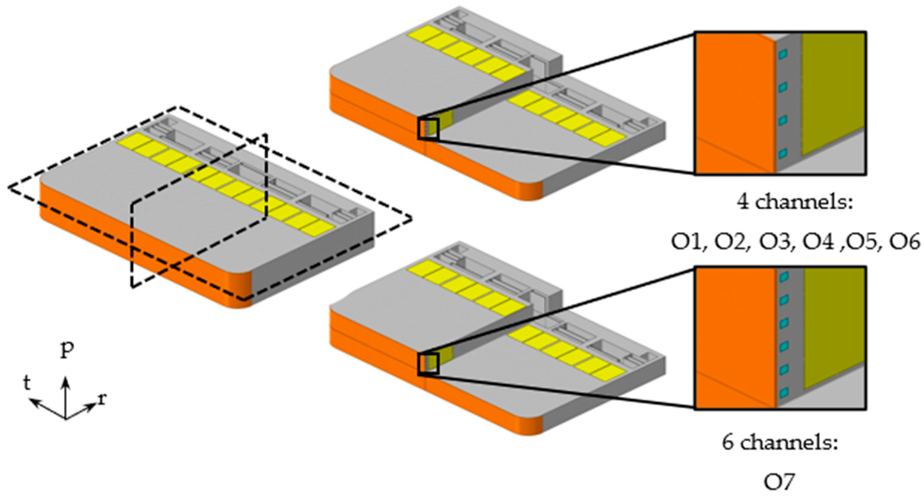
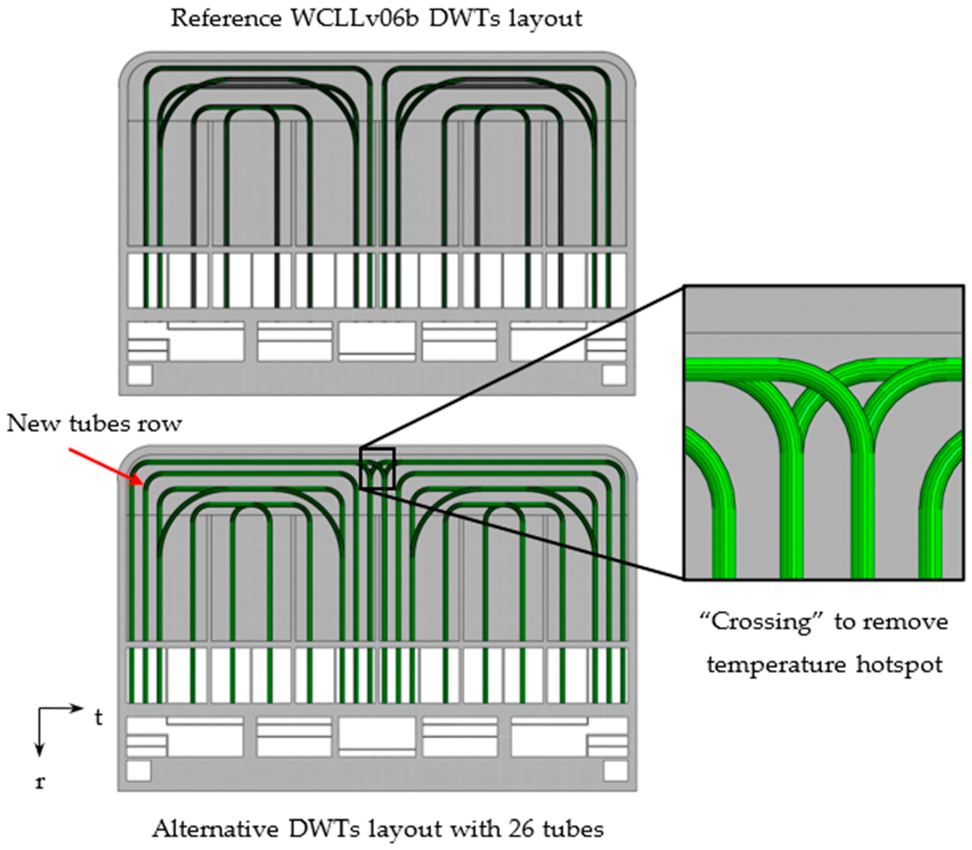
3.2.1. DWTs and FW Channels Thermal Optimization

In order to thermally optimize the WCLL COB segment, three alternative DWTs layouts foreseeing 22, 24 and 26 “crossed” DWTs per elementary cell were set-up, foreseeing the crossing of the first row of tubes to remove the temperature hotspot in the central region of the cell (Figure 7). Moreover, the configurations with 24 and 26 DWTs per slice were obtained by moving along the radial and the toroidal directions of the first two rows of tubes and adding a new row of tubes, consisting of 2 or 4 tubes, respectively (Figure 8). Regarding the O6 region, the FW-SW was equipped with 6 channels per cell as well.
In order to study the thermal behaviour of the three alternative DWTs configurations on each WCLL COB poloidal region to be optimized, a couple of elementary cells equipped with 26, 24 and 22 “crossed” DWTs were studied. Three FEM models, with a mesh composed of ~3M nodes connected in ~4M linear hexahedral and tetrahedral elements, were set-up for each region. Then, loads and boundary conditions already discussed above were considered. Finally, a parametric set of thermal analysis was launched with the aim of achieving the DWTs configuration for each COB poloidal region capable of removing the heat, while keeping the temperature below 550 °C, with the minimum number of tubes.
Results are synthetically summarized in Table 4, where the DWTs layout configuration selected, the number of FW-SW channels for each COB region and, moreover, the corresponding maximum temperature reached on the SPs and FW are shown. In particular, in Table 4 the labels “v06b ref.”, “alt. 22” and “alt. 24” indicate the reference layout v06b and the two alternative DWTs configurations equipped with 22 and 24 tubes, respectively.

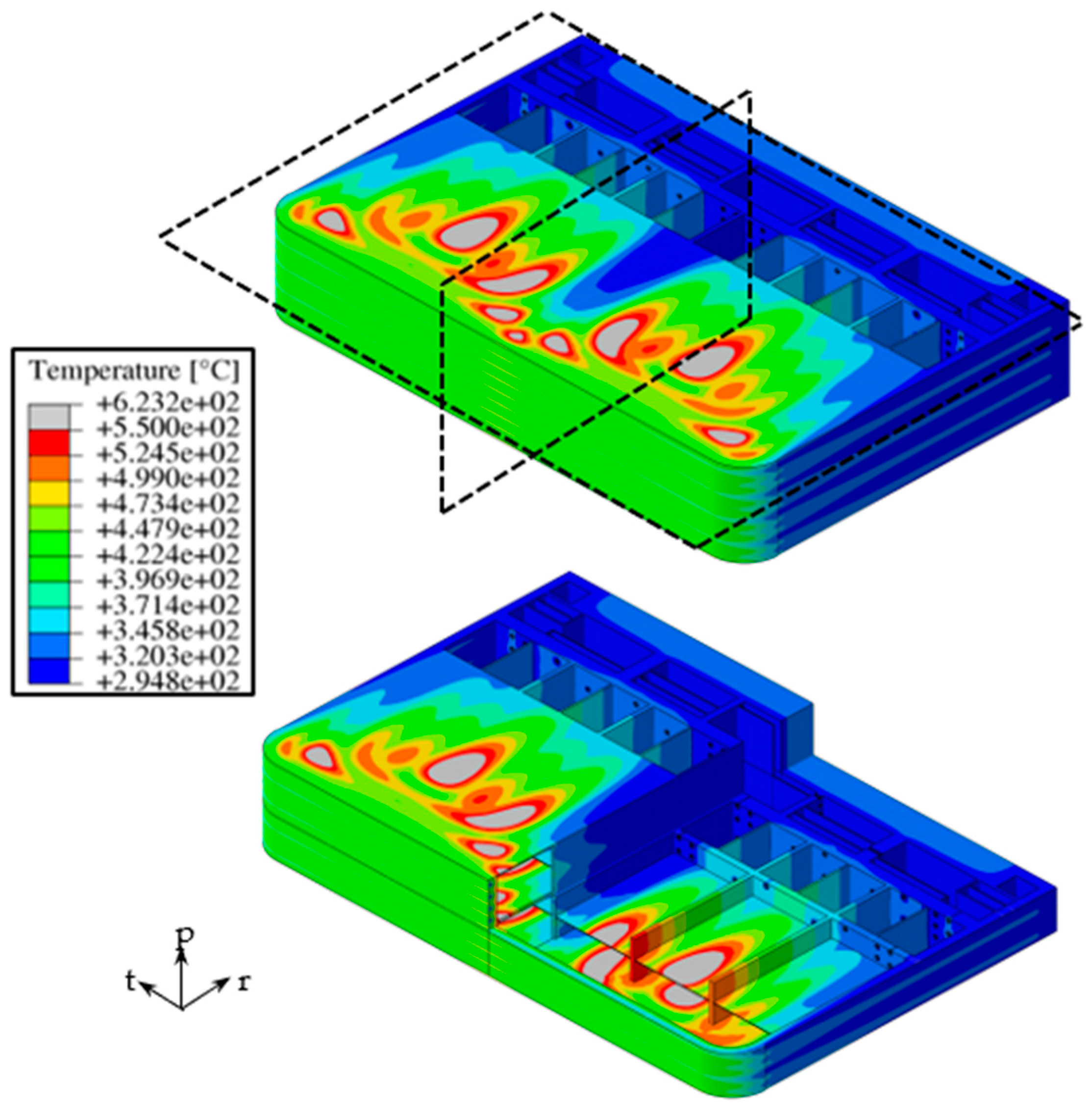
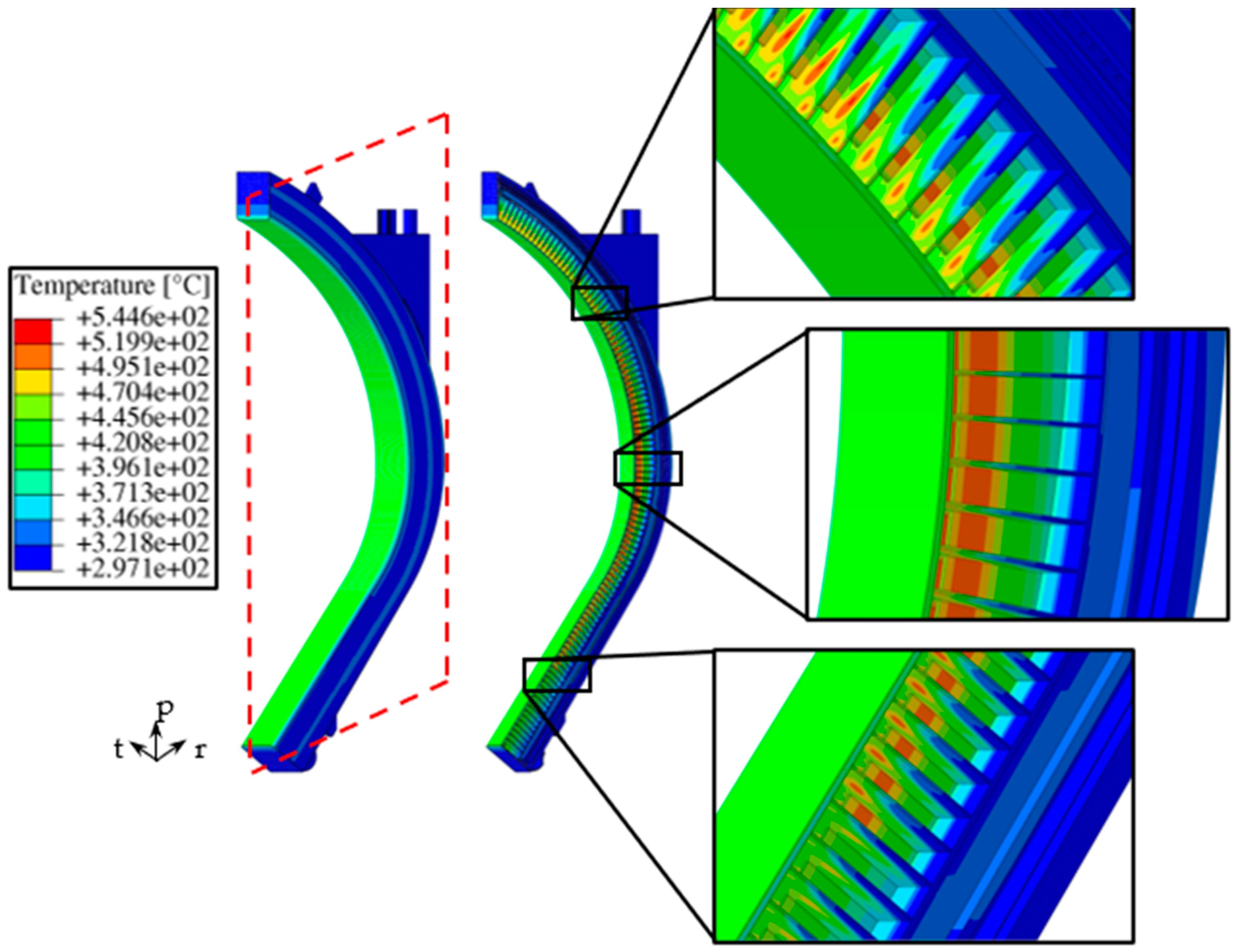
3.2.2. Determination of a Thermal Field for the Whole WCLL COB Segment

The outcomes of the previous optimization study were used in order to represent in the most realistic way the thermal field arising in the whole WCLL COB segment. Indeed, starting from the optimized thermal field calculated in each of the seven equatorial cells, an interpolation procedure [5] was performed to obtain seven different sets of functions of the radial and the toroidal variable. Then, a proper Fortran subroutine (named “UDISP”) was set up to provide the poloidal dependence so to obtain a different 3D thermal field for each of the seven WCLL COB poloidal regions. Lastly, the seven thermal fields were stitched together to give the 3D spatial temperature distribution for the whole WCLL COB segment.
To perform the interpolation, each equatorial cell was divided into 13 different regions: one for the SW-FW-SW and one for the manifolds region; one for each vertical SP, for a total of five regions; and six for each horizontal SP, identified by the five poloidal-radial SPs. Successively, a polynomial function of the radial and toroidal variables was drawn for each region to represent its temperature distributions. A set of 13 polynomial functions was then built up for each COB poloidal region to reproduce the thermal field in the most accurate way. In particular, a 14th degree polynomial function of two variables (r and t directions) was selected for the SW-FW-SW regions, up to 9th degree polynomial function of one variable (r direction) for the manifolds, up to 10th degree polynomial functions of two variables (r and t directions) for each SPh, and up to 14th degree polynomial functions of one variable (r direction) for each SPv. Concerning the Caps, since their cooling system has not yet been studied in detail, a polynomial function of one variable (r direction) was obtained from the SWs region and applied to the whole plate, while, on the corresponding FW region, the same polynomial function of the nearest poloidal region (namely O1 and O7) was used.
The obtained thermal field is depicted in Figure 9 with some details at different poloidal heights of the segment. Moreover, a uniform temperature value of 300 °C was considered for the supports (namely the attachment system) in charge of connecting the segment to the VV.

4. Structural Analysis of the Reference COB Segment

Once a reliable and detailed thermal field of the whole WCLL COB segment was obtained, its structural performances under different steady state loading scenarios was assessed. To this end, since Baffle Plates and DWTs have no structural role, they were not considered in the pertinent FEM model, in order to reduce the computational burden. Therefore, a FEM model was created on Abaqus and a mesh composed of ~3.2M nodes connected in ~8.7M tetrahedral and hexahedral elements was set up.

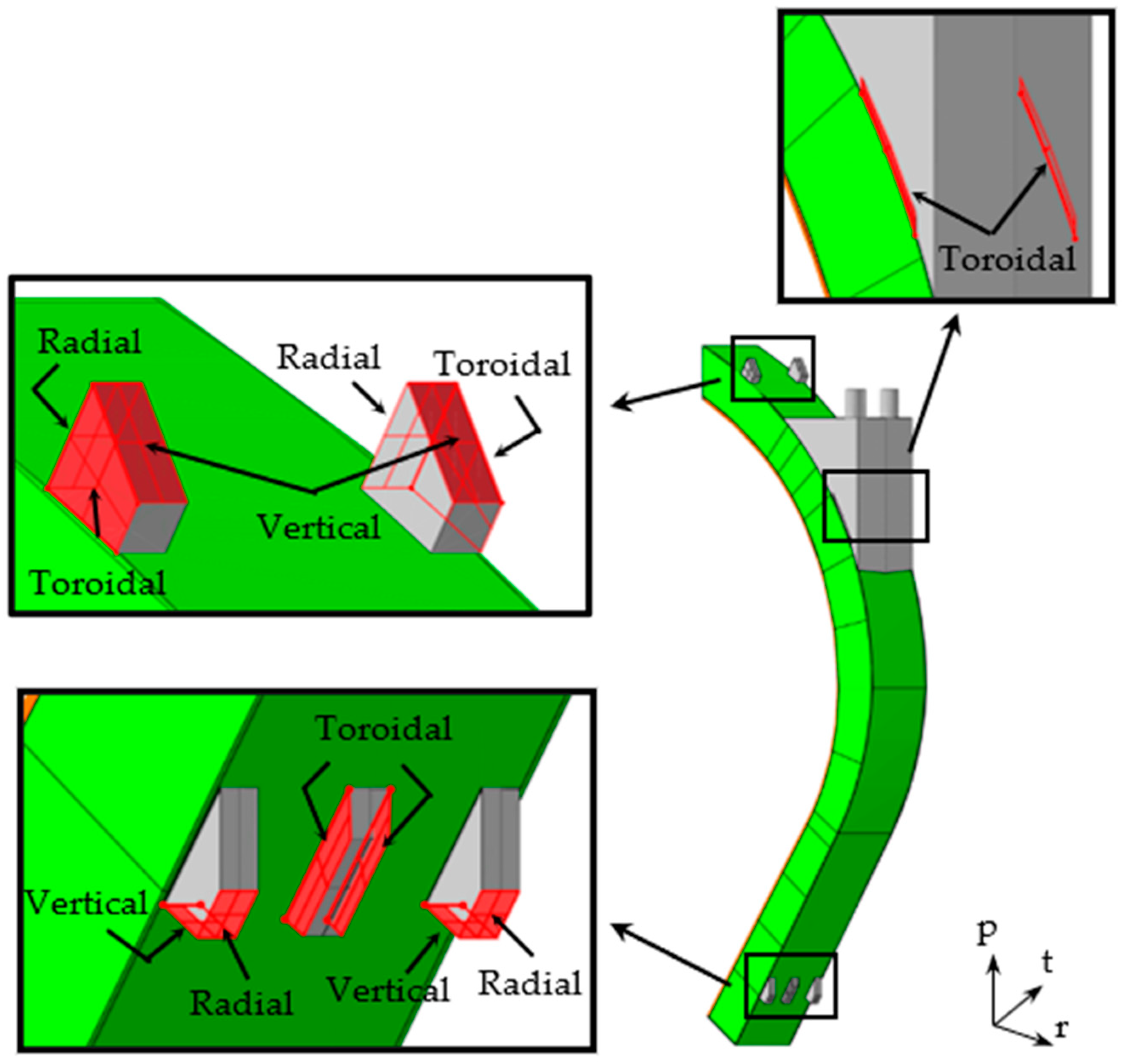
4.1. Loads and Boundary Conditions

The assessment of the thermo-mechanical behaviour of the reference COB segment foresees its evaluation under different steady state loading scenario. In particular, the loading scenarios considered were: Normal Operation (NO), Over-Pressurization (OP) and an Upper Vertical Displacement Event (UVDE). The NO scenario represented the nominal conditions that the WCLL COB is supposed to undergo during flat-top plasma. In contrast, the OP scenario is a load combination derived from the in-box LOCA. This scenario was derived supposing that the occurrence of an in-box LOCA suddenly pressurizes the whole SB. Lastly, the UVDE scenario took into account the very intense electro-magnetic loads due to an uncontrolled vertical movement of the plasma, causing a plasma disruption. The loading conditions relevant to the steady state scenario of NO, OP and UVDE were classified as Level A, Level D and Level C, respectively, in the RCC-MRx structural design code.
In order to predict the structural response of the COB segment, a set of loads and boundary conditions was assumed to reproduce the three assessed loading scenarios [15].
  • internal pressure distribution according to the considered loading scenario;
  • mechanical restraints;
  • gravity load;
  • non-uniform deformation thermal field;
  • electro-magnetic loads.
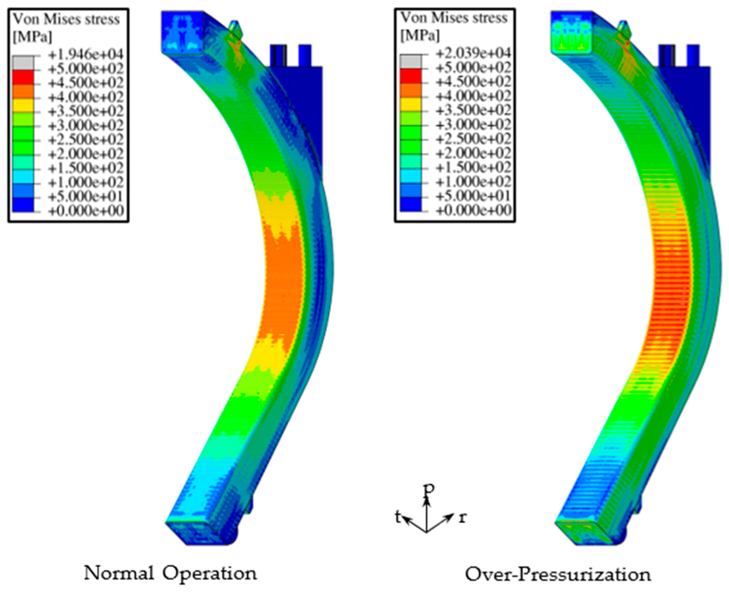
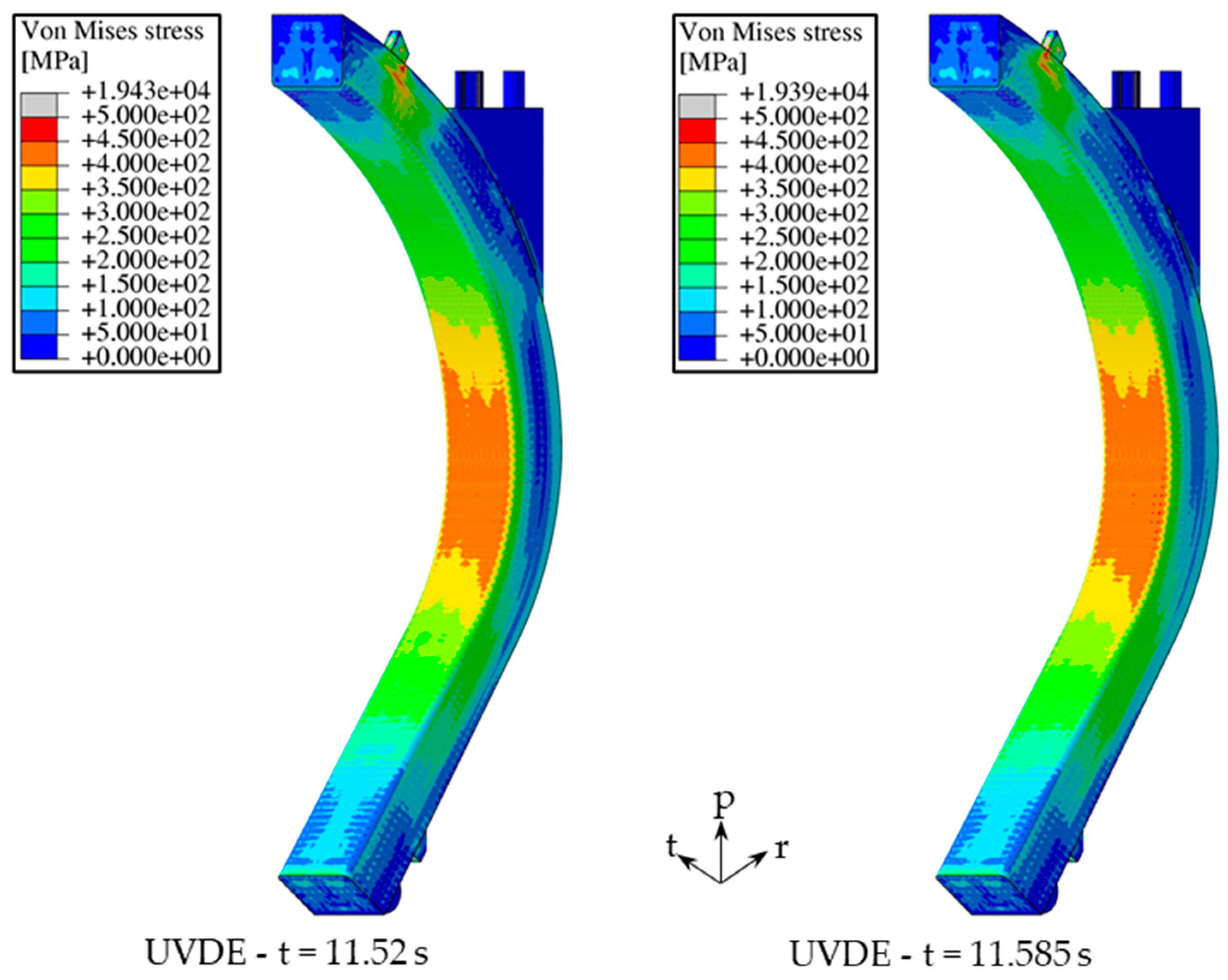
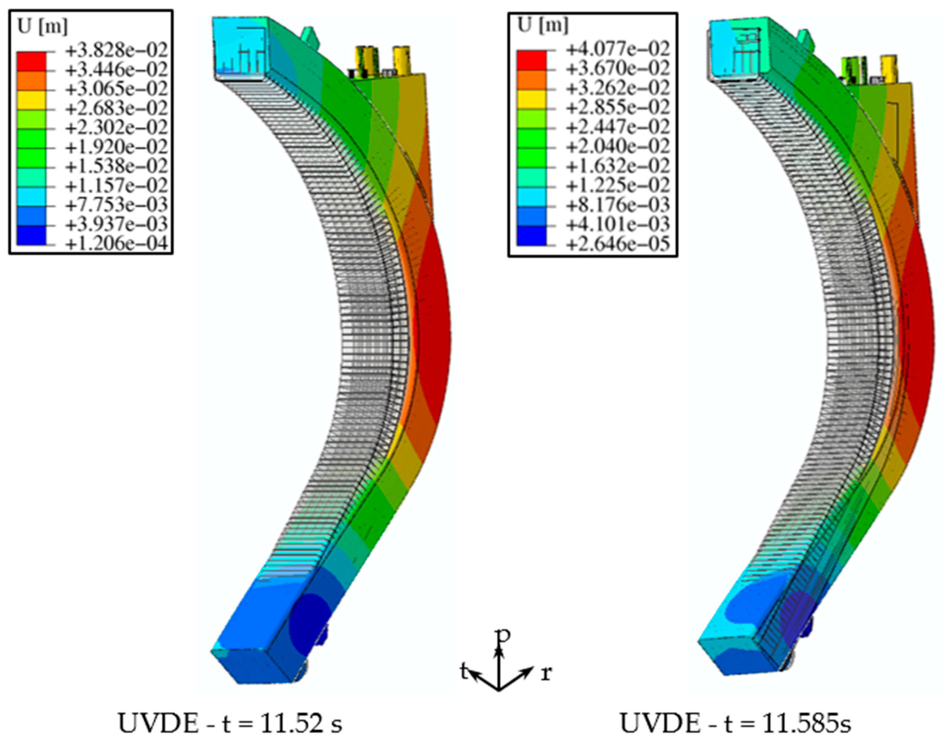
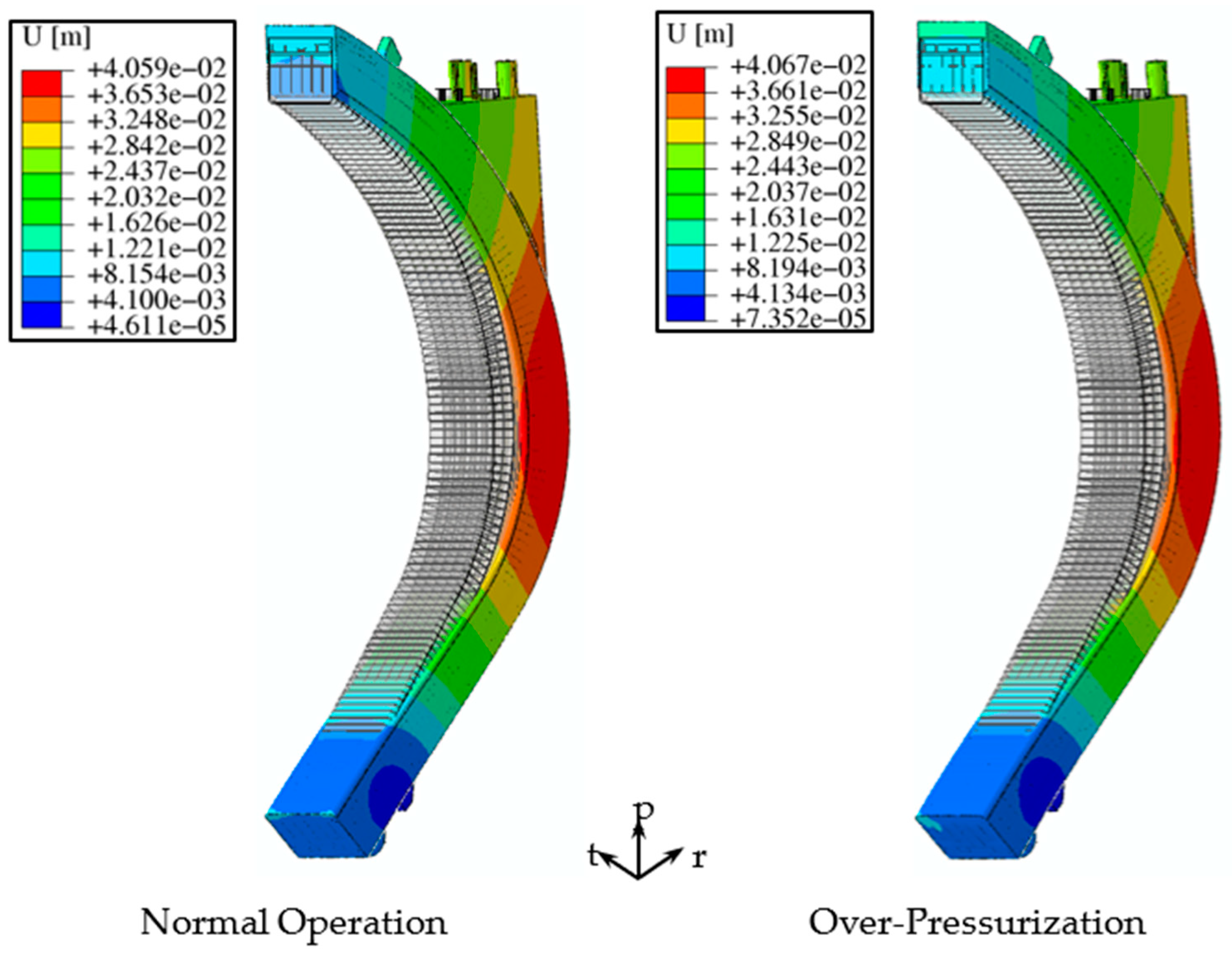
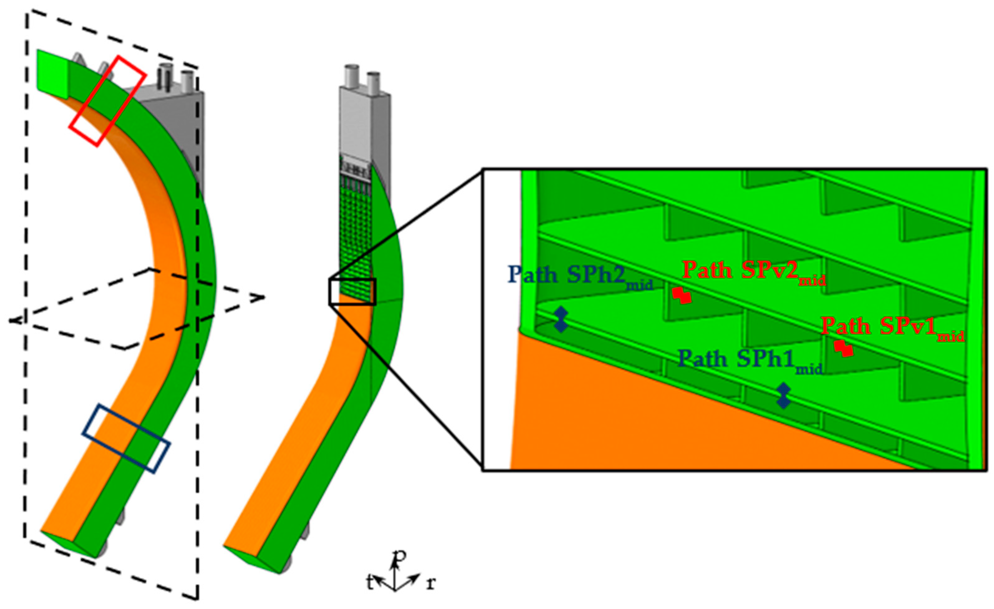
Since neither breeder nor water has been modelled, in order to reproduce their mechanical effect, a uniform pressure value was imposed upon all the wetted surfaces. In particular, the design pressure value, calculated as the nominal one times a safety factor equal to 1.15 [15], was imposed onto both breeder-wetted and water-wetted surfaces. So, for NO and UVDE loading scenario, a pressure equal to 17.825 MPa was considered for all the water-wetted surfaces; instead, a value equal to 0.575 was applied to the surfaces wetted by the PbLi. An equal value of 17.825 was considered for all the internal wetted surfaces in the OP loading scenario.
Additionally, the reference attachment system consisted of a set of supports aimed at fixing the blanket segments to the VV and, at the same time, withstanding very large electro-magnetic loads, thermal deformations and maintaining a good alignment of the FW. The supports were located at the bottom and at the top part of the segment and each face of these supports worked along a particular direction, as reported in Figure 10, thus ensuring the segment connection with the VV [16]. These contacts were simulated by means of springs, particular Abaqus element, in correspondence to each surface. So, each of the springs was assigned a specific value of elastic constant.
The gravitational load has been also applied to the whole model. However, since the liquid metal breeder and coolant were not modelled, their contribution was taken into account using an Eurofer equivalent density, as already done in previous analyses. The equivalent density value was obtained assuming that the percentage of steel, water and breeder were equal to that calculated for the equatorial region. So, temperature-dependent properties of Tungsten and Eurofer structural steel [9,11] were taken into account and implemented in the model, properly modifying the Eurofer density values.
As to the non-uniform deformation thermal field, it arose within the structure as an effect of the imposed temperature spatial distribution (Figure 9) and the volumetric expansion coefficient.
Finally, the electro-magnetic loads were also considered for all the assessed steady state loading scenarios. In fact, their action during normal and off-normal operation cannot be neglected and must be included during the investigation of the COB structural response [17]. Since steady state analyses were performed, the EM loads considered and used were relative to a specific instant of time, i.e., time step. During both the NO and OP loading scenario, as prescribed by [15], the same EM loads were considered. In particular, only the ferromagnetic loads contribution was considered, since the Lorentz’s forces one is negligible. Instead, this assumption cannot be done for the UVDE loading scenario and the Lorentz’s forces needed to be taken into account. So, as already done in [18], the EM loads related to two different time steps were considered for the thermo-mechanical evaluation under the UVDE loading scenario: the time steps corresponding to the maximum of the radial forces and moment, t = 11.52 s and t = 11.585 s, respectively. Thanks to a purposely developed computational procedure, the EM loads, calculated separately through a dedicated electro-magnetic analysis, were applied to the node mesh of the COB segment model. In particular, this procedure allowed matching the cloud of points on which the EM forces are calculated to the structural analysis mesh. Since the former was much coarser than the latter, the developed procedure was capable of assigning the EM forces calculated at the point (x, y, z) to the closest node of the structural analysis mesh. Since the EM model took into account the presence of breeder and DWTs, which are absent in the COB segment FEM model, the EM values in that regions were allocated to the nearby Eurofer portion in order to conservatively consider their effects.

4.2. Results

Steady state analyses of the reference COB segment under different loading scenarios were performed with the aim of evaluating its structural behaviour, as well as verifying that the safety criteria of the RCC-MRx for the structural material were fulfilled.
So, the von Mises equivalent stress fields obtained for each different loading scenario are reported in Figure 11 and Figure 12, in which only the Eurofer structural material is displayed. The deformed vs. undeformed shapes are likewise depicted in Figure 13 and Figure 14, also with the displacement fields for each assessed scenario. In particular, the deformed shapes are shown with an isotropic amplification factor equal to 20. Looking at the displacement fields, in each operating scenario analysed, the maximum displacement occured along the radial direction, as well as, looking the von Mises stress fields, the equatorial region being the particularly stressed one. In Table 5 the maximum and minimum values of displacement along all directions for all the assessed scenarios are reported, where Ur, Ut and Up indicate the displacements along the radial, toroidal and poloidal direction, respectively. The values obtained show the same trend and the largest displacement occurs in all the assessed scenarios along the radial direction, with the highest value raised in the OP loading scenario. Moreover, in the UVDE scenario, when the EM loads are considered at the time step of 11.585 s (maximum of radial moments), a larger displacement in toroidal direction than in the other scenarios can be highlighted.
In the end, a stress linearization procedure was performed along some significant paths located within the most stressed regions of the structure. Then, the fulfilment of Level A, C and D criteria, namely, for the NO, UVDE and OP loading scenario, respectively, prescribed by the RCC-MRx design code along them was checked. In particular, four criteria were taken into account for the structural evaluation: Immediate Excessive Deformation (IED), Immediate Plastic Instability (IPI), Immediate Plastic Flow Localization (IPFL) and Immediate Fracture due to exhaustion of ductility (IF). While the first two criteria only considered the primary stresses, the others also took into account secondary stresses occurring along the analysed path. For each criterion, the stress limit values were calculated, for the service level (A, C or D) to which each loading scenario analysed relates, in accordance with the structural material and the average path temperature. Therefore, since the cooling channels located within the FW-SW region were not modelled to reduce the computational burden, only the SPs grid was considered from the mechanical point of view and some paths lying on the poloidal-radial and toroidal-radial SPs (Figure 15), at three different poloidal height, highlighted in red and blue in Figure 15, were individuated.
The obtained results are reported in Table 6, Table 7, Table 8 and Table 9, also representing the average temperature values arising within each path. For each criterion, the ratio between the equivalent stress value and the corresponding stress limit is reported in the tables where the values greater than 1 are highlighted in red, indicating that the criterion was not fulfilled within the selected path. The evaluation of the results of the RCC-MRx criteria indicated that the vertical SPs were particularly stressed, in particular the path named SPv2, in each poloidal height considered. In each considered loading scenario, these paths did not totally fulfill the criteria for the immediate plastic flow localization, namely the (Pm + Qm)/Sem, unlike the path within the central poloidal-radial SP, which, due to its lower average temperature, verified this criterion in every operating scenario and at every segment height considered. Moreover, the path SPh1, located in the central part of a horizontal SP in the upper region, also did not fulfil the IPFL criterion, taking into account the secondary stresses. Globally, average temperatures were higher in the regions in which the criterion for the Immediate Plastic Flow Localization was not fulfilled, as reported in tables. Therefore, high temperatures, together with the action of the selected attachment system, could contribute to the failure of the RCC-MRx criteria verification.

5. Conclusions

In the frame of the European DEMO BB research activities, a study was carried out with the aim of investigating the thermomechanical performances of the DEMO WCLL COB under NO, UVDE and OP steady state loading scenarios, ensuring the fulfilment of the thermal and structural design requirements, the latter represented by the RCC-MRx structural design criteria. Once the cooling scheme from the thermal point of view was optimized, structural analyses were performed.
All the assessed scenarios showed a similar displacements field, with an evident radial displacement in the equatorial region, suggesting a revision of the attachment system to limit the displacement in this direction of the structure.
Concerning the fulfillment of the criteria of RCC-MRx design code, not all the criteria were fulfilled in the paths taken into consideration and, especially, the criterion considering the secondary stresses, namely, the Immediate Plastic Flow Localization, probably due to the resistance exerted by the SPs against the thermal expansion. Moreover, as the SB channels were not modelled due to the modelling assumption, no path was investigated within the highly stressed FW-SW region.
The present study concludes that the optimized WCLL COB segment geometric layout is also promising from the structural point of view, even though further analyses are necessary in order to study in detail the structural behaviour of the FW-SW region at different poloidal height of the COB segment, possibly adopting an updated version of the attachment system.

Author Contributions

Conceptualization, I.C., G.B. and P.A.D.M.; methodology, I.C., G.B. and P.A.D.M.; formal analysis, I.C., G.B. and P.A.D.M.; investigation, I.C. and G.B.; resources, I.C., G.B. and P.A.D.M.; data curation, I.C. and G.B.; writing—original draft preparation, I.C. and G.B.; writing—review and editing, I.C., G.B. and P.A.D.M.; visualization, I.C. and G.B.; supervision, P.A.D.M.; project administration, P.A.D.M.; funding acquisition, P.A.D.M. All authors have read and agreed to the published version of the manuscript.

Funding

This work has been carried out within the framework of the EUROfusion Consortium and has received funding from the Euratom research and training programme 2014 to 2018 and 2019 to 2020 under grant agreement No 633053. The views and opinions expressed herein do not necessarily reflect those of the European Commission.

Data Availability Statement

Data available on request from the authors.

Conflicts of Interest

The authors declare no conflict of interest.

References

  1. Cismondi, F.; Spagnuolo, G.A.; Boccaccini, L.; Chiovaro, P.; Ciattaglia, S.; Cristescu, I.; Day, C.; Del Nevo, A.; Di Maio, P.A.; Federici, G.; et al. Progress of the conceptual design of the European DEMO breeding blanket, tritium extraction and coolant purification systems. Fusion Eng. Des. 2020, 157, 111640. [Google Scholar] [CrossRef] [Green Version]
  2. Federici, G.; Boccaccini, L.; Cismondi, F.; Gasparotto, M.; Poitevin, Y.; Ricapito, I. An overview of the EU breeding blanket design strategy as an integral part of the DEMO design effort. Fusion Eng. Des. 2019, 141, 30–42. [Google Scholar] [CrossRef]
  3. Arena, P.; Del Nevo, A.; Moro, F.; Noce, S.; Mozzillo, R.; Imbriani, V.; Giannetti, F.; Edemetti, F.; Froio, A.; Savoldi, L.; et al. The DEMO Water-Cooled Lead-Lithium Breeding Blanket: Design status at the end of the Pre-Conceptual Design Phase. Appl. Sci. 2021, 11, 11592. [Google Scholar] [CrossRef]
  4. D’Amico, S.; Di Maio, P.A.; Jin, X.Z.; González, F.A.H.; Moscato, I.; Zhou, G. Preliminary thermal-hydraulic analysis of the EU-DEMO Helium-Cooled Pebble Bed fusion reactor by using the RELAP5-3D system code. Fusion Eng. Des. 2021, 162, 112111. [Google Scholar] [CrossRef]
  5. Catanzaro, I. Development and application of an alternative modelling approach for the thermo-mechanical analysis of a DEMO Water-Cooled Lithium Lead breeding blanket segment. Department of Engineering, University of Palermo, Palermo, Italy. 2021; under review. [Google Scholar]
  6. RCC-MRx, Design and Construction Rules for Mechanical Components of Nuclear Installations; AFCEN: Courbevoie, France, 2013.
  7. Abaqus Analysis User’s Guide: Online Documentation; Version 6.14-2; Dassault System; Simulia: Providence, RI, USA, 2015.
  8. Maviglia, F.; Vizvary, Z.; Richiusa, M.L.; Gerardin, J.; Firdaouss, M. DEMO PFC Surface Heat Load Specifications. 2020. Available online: http://idm.euro-fusion.org/?uid=2P985Q (accessed on 30 November 2021).
  9. Gaganidze, E. Material Properties Handbook—EUROFER97. 2020. Available online: http://idm.euro-fusion.org/?uid=2NZHBS (accessed on 30 November 2021).
  10. Martelli, D.; Venturini, A.; Utili, M. Literature review of lead-lithium thermophysical properties. Fusion Eng. Des. 2018, 183–195. [Google Scholar] [CrossRef]
  11. Gaganidze, E.; Schoofs, F. Material Properties Handbook—Tungsten. 2020. Available online: http://idm.euro-fusion.org/?uid=2P3SPL (accessed on 30 November 2021).
  12. Berry, T.; Eade, T. Activation Analysis and Evaluation of Inventories, Decay Heat, for Important Components—Activity 2019—CCFE Contribution (Calculation of Decay Heat in PbLi for Entire WCLL Reactor). Available online: http://idm.euro-fusion.org/?uid=2NQL5P (accessed on 30 November 2021).
  13. Incropera, F.P.; Dewitt, D.P.; Bergman, T.L.; Lavine, A.S. Principles of Heat and Mass Transfer, 7th ed.; Wiley: Hoboken, NJ, USA, 2013. [Google Scholar]
  14. Di Maio, P.A.; Arena, P.; Bongiovì, G.; Chiovaro, P.; Del Nevo, A.; Richiusa, M.L. On the numerical assessment of the thermo-mechanical behaviour of the DEMO Water Cooled Lithium Lead equatorial outboard blanket module. Fusion Eng. Des. 2017, 124, 725–729. [Google Scholar] [CrossRef]
  15. Spagnuolo, G.A.; Boccaccini, L.; Bongiovì, G.; Cismondi, F.; Maione, I. Development of load specifications for the design of the breeding blanket system. Fusion Eng. Des. 2020, 157, 111657. [Google Scholar] [CrossRef] [Green Version]
  16. Bachmann, C. IDD—Blanket Mechanical Supports. 2019. Available online: http://idm.euro-fusion.org/?uid=2NHC86 (accessed on 30 November 2021).
  17. Maione, I.A.; Lucca, F.; Marin, A.; Bertolini, C.; Roccella, M.; Villone, F.; Del Nevo, A. Analysis of EM loads on DEMO WCLL Breeding Blanket during VDE-up. Fusion Eng. Des. 2018, 136, 1523–1528. [Google Scholar] [CrossRef] [Green Version]
  18. Catanzaro, I.; Arena, P.; Basile, S.; Bongiovì, G.; Chiovaro, P.; Del Nevo, A.; Di Maio, P.A.; Forte, R.; Maione, I.A.; Vallone, E. Structural assessment of the EU DEMO WCLL Central Outboard Blanket segment under normal and off-normal operating conditions. Fusion Eng. Des. 2021, 167, 112350. [Google Scholar] [CrossRef]
Figure 1. Poloidal Segmentation of the DEMO BB and numbering of the Inboard and Outboard poloidal regions.
Applsci 12 01356 g001
Figure 2. COB Segment architecture and detail of the main components.
Applsci 12 01356 g002
Figure 3. WCLL v06b DWTs layout and recirculation scheme (inlet in red, first outlet/recirculation in orange, exit in green).
Applsci 12 01356 g003
Figure 4. Models of the two elementary cells equipped with 4 and 6 cooling channels.
Applsci 12 01356 g004
Figure 5. Thermal field raised within the Eurofer domain of the O4 region.
Applsci 12 01356 g005
Figure 6. Thermal field raised within the Eurofer domain of the O6 region.
Applsci 12 01356 g006
Figure 7. Alternative DWTs layout and detail of the crossing tubes.
Applsci 12 01356 g007
Figure 8. Alternative DWTs layout equipped with 26, 24, and 22 tubes.
Applsci 12 01356 g008
Figure 9. Thermal field obtained for the whole WCLL COB segment by the interpolation procedure.
Applsci 12 01356 g009
Figure 10. WCLL COB attachment system and indication of the directions of action of the springs.
Applsci 12 01356 g010
Figure 11. Von Mises stress field under NO and OP loading scenarios.
Applsci 12 01356 g011
Figure 12. Von Mises stress field under UVDE (t = 11.52 s and t = 11.585 s) loading scenarios.
Applsci 12 01356 g012
Figure 13. Deformed vs. Undeformed shapes under NO and OP loading scenarios.
Applsci 12 01356 g013
Figure 14. Deformed vs. Undeformed shapes under UVDE (t = 11.52 s and t = 11.585 s) loading scenarios.
Applsci 12 01356 g014
Figure 15. Paths within SPs grid in the equatorial region.
Applsci 12 01356 g015
Table 1. Total Heat Flux and average NWL poloidal distribution.
O1O2O3O4O5O6O7
Maximum Heat Flux [MW/m2]0.240.270.260.270.270.670.67
Average NWL [MW/m2]0.98341.15921.28021.33351.32871.18440.7539
Table 2. HTC values used for cooling channels and DWTs coolant.
O1O2O3O4O5O6O7
HTCCC
[W/m2∙K]
31,36833,60934,49035,57035,51838,89536,167
HTCDWTs
[W/m2∙K]
16,96519,90119,25819,90519,84720,03313,576
HTCDWTs,rec
[W/m2∙K]
26,54531,13933,53034,65634,55631,34621,243
Table 3. Maximum temperature per region equipped with v06b layout.
O1O2O3O4O5O6O7
Tmax on FW [°C]478.2503.3519.0526.6525.9566.4479.2
Tmax on SPs [°C]546.7580.5603.1612.9612.1585.2501.0
Table 4. BZ and FW-SW cooling layout per poloidal region.
O1O2O3O4O5O6O7
n. channels4444466
DWTs layoutv06b ref.alt. 22alt. 24alt. 24alt. 24alt.22v06b ref.
Tmax on SPs [°C]546.7534.0531.4538.9538.2539.2501.0
Tmax of FW [°C]478.2484.6497.8504.6504.0474.6479.2
Table 5. Maximum and minimum displacements values obtained.
NOOPUVDE
(t = 11.52 s)
UVDE
(t = 11.585 s)
Ur, max [mm]40.346140.531437.913740.3827
Ur, min [mm]−9.71531−9.59273−9.58886−9.56706
Ut, max [mm]5.460145.596496.195657.99158
Ut, min [mm]−5.0945−4.82734−5.11112−12.4684
Up, max [mm]23.732623.535723.965323.9025
Up, min [mm]−5.01018−5.88849−4.63463−5.45198
Table 6. Verification of RCC-MRx criteria under NO loading scenario.
Normal Operation
Tave [°C]Pm/Sm(Pm + Pb)/(Keff·Sm)(Pm + Qm)/Sem(Pm + Pb + Q + F)/Set
SPv1,mid346.00.3880.2590.6510.156
SPv2,mid519.30.5050.3372.0660.291
SPh1,mid435.60.1780.1200.5770.104
SPh2,mid473.00.1740.1240.7260.119
SPv1,top325.40.4520.3020.3280.078
SPv2,top462.60.5950.3981.3000.218
SPh1,top400.60.0840.0671.0290.216
SPh2,top458.80.2220.1770.7920.130
SPv1,bot339.20.0500.0330.2290.055
SPv2,bot503.70.0690.0481.4610.216
SPh1,bot430.00.0940.0880.7940.163
SPh2,bot478.10.0830.0580.8840.147
Table 7. Verification of RCC-MRx criteria under OP loading scenario.
Over-Pressurization
Tave [°C]Pm/Sm(Pm + Pb)/(Keff·Sm)(Pm + Qm)/Sem(Pm + Pb + Q + F)/Set
SPv1,mid346.00.3420.2280.3830.110
SPv2,mid519.30.4010.2681.2170.166
SPh1,mid435.60.8320.5590.6750.125
SPh2,mid473.00.7120.4820.6320.103
SPv1,top325.40.2140.1420.3120.089
SPv2,top462.60.2010.1360.6240.105
SPh1,top400.60.7250.4860.9570.213
SPh2,top458.80.6120.4090.6490.103
SPv1,bot339.20.2630.1750.2540.073
SPv2,bot503.70.2420.1610.8220.118
SPh1,bot430.00.7560.5170.7880.160
SPh2,bot478.10.6600.4410.6930.113
Table 8. Verification of RCC-MRx criteria under UVDE (t = 11.52 s) loading scenario.
UVDE (t = 11.52 s)
Tave [°C]Pm/Sm(Pm + Pb)/(Keff·Sm)(Pm + Qm)/Sem(Pm + Pb + Q + F)/Set
SPv1,mid346.00.2730.1820.5530.1326
SPv2,mid519.30.3370.2371.7390.246
SPh1,mid435.60.1550.1040.4890.088
SPh2,mid473.00.1550.1460.6150.104
SPv1,top325.40.2910.1950.2630.063
SPv2,top462.60.4020.2731.0630.179
SPh1,top400.60.0760.0600.8650.182
SPh2,top458.80.1870.1490.6530.108
SPv1,bot339.20.0880.0590.1770.042
SPv2,bot503.70.1050.0701.1850.175
SPh1,bot430.00.0920.0820.6740.138
SPh2,bot478.10.0800.0570.7500.126
Table 9. Verification of RCC-MRx criteria under UVDE (t = 11.585 s) loading scenario.
UVDE (t = 11.585 s)
Tave [°C]Pm/Sm(Pm + Pb)/(Keff·Sm)(Pm + Qm)/Sem(Pm + Pb + Q + F)/Set
SPv1,mid346.00.2920.1990.5420.130
SPv2,mid519.30.4110.3181.7060.245
SPh1,mid435.60.1360.0970.4800.087
SPh2,mid473.00.1460.2180.6120.111
SPv1,top325.40.3220.2170.2810.068
SPv2,top462.60.5110.3561.0940.184
SPh1,top400.60.0850.0640.8650.182
SPh2,top458.80.1650.1510.6660.111
SPv1,bot339.20.0440.0300.1990.048
SPv2,bot503.70.0510.0351.2500.185
SPh1,bot430.00.1290.1140.6680.139
SPh2,bot478.10.0450.0590.7040.120
Publisher’s Note: MDPI stays neutral with regard to jurisdictional claims in published maps and institutional affiliations.

