Article

Application of Inelastic Method and Its Comparison with Elastic Method for the Assessment of In-Box LOCA Event on EU DEMO HCPB Breeding Blanket Cap Region

by
Anoop Retheesh
*,
Francisco A. Hernández
and
Guangming Zhou
Karlsruhe Institute of Technology (KIT), Institute for Neutron Physics and Reactor Technology (INR), Hermann-von-Helmholtz-Platz 1, 76344 Eggenstein-Leopoldshafen, Germany
*
Author to whom correspondence should be addressed.
Appl. Sci. 2021, 11(19), 9104; https://doi.org/10.3390/app11199104
Submission received: 31 August 2021 / Revised: 24 September 2021 / Accepted: 27 September 2021 / Published: 30 September 2021
(This article belongs to the Special Issue Structural and Thermo-Mechanical Analyses in Nuclear Fusion Reactors)

Abstract

:
The Helium Cooled Pebble Bed (HCPB) breeding blanket, being developed by the Karlsruhe Institute of Technology (KIT) and its partners is one of the two driver blanket candidates to be selected for the European demonstration fusion power plant (EU DEMO). The in-box Loss of Coolant Accident (LOCA) is a postulated initiating event of the breeding blanket (BB) that must be accounted within the design basis. In this paper, the BB cap region is analyzed for its ability to withstand an in-box LOCA event. Initially, an assessment is performed using conventional elastic design codes for nuclear pressure vessels. However, it is thought that the elastic rules are not ‘equipped’ to assess the material damage modes which are essentially inelastic. Therefore, a non-linear inelastic analysis is further performed to better understand the damage in the material. Two predominant inelastic failure modes are thought to be relevant and addressed: exhaustion of ductility and plastic flow localization. While the design of HCPB BB has been predominantly based on the elastic design-by-analysis studies, results from the present study show that the elastic rules may be overly conservative for the given material and loading and could lead to inefficient designs. To our knowledge, this study is the first attempt to investigate the structural integrity of the European DEMO blankets under in-box LOCA conditions using the inelastic methods.

1. Introduction

The EU DEMO denotes a crucial step between the International Thermonuclear Experimental Reactor (ITER) and the commercial generation of fusion power in Europe [1]. The HCPB breeding blanket is one of the two “driver” blanket concepts being considered for the EU DEMO [2]. The reference structural material for EU DEMO blankets is a Reduced Activation Ferritic-Martensitic (RAFM) steel: Eurofer97, which is capable of withstanding high neutron irradiation with low-activation. While for ITER, due to its experimental nature, an austenitic stainless steel type 316L(N)-IG is used as the structural material for the blankets is [3]. Figure 1 shows a brief overview of the present HCPB BB concept within the DEMO tokamak. Each BB segment consists of a breeder zone volume formed between a first wall and a backplate, which is supported by a back supporting structure (BSS). The breeder zone is filled with a hexagonal arrangement of pressure tubes connecting the first wall and the backplate and acting as radial stiffeners. The ceramic breeder material (Li4SiO4 + 35% mol Li2TiO3) in the form of a pebble bed is filled inside breeder pins and inserted into each of the pressure tubes. Further, the pressure tubes are surrounded by hexagonally shaped (prismatic) neutron multiplier blocks (NMB) made up of Beryllium alloy (Be12Ti). More details of the present HCPB BB architecture can be found in [4].
Several HCPB BB concepts were extensively investigated using linear design-by-analysis methods with respect to codes and standards over the last decade [5,6,7,8,9,10,11,12,13,14]. Additionally, a few studies employed non-linear methods to conduct the failure analysis under normal operation (NO) conditions [15,16,17]. In-box LOCA is an identified design basis accident scenario [13,14,18] for the BB, in which the blanket box has to withstand the pressure exerted by the leakage of high-pressure coolant. The structural assessments of the HCPB breeding blanket under the in-box LOCA conditions are carried out in [5,9,14].
In contrast to the breeding zone at other regions, the cap region of the BB is considered predominantly a structural element, which does not contribute largely to tritium breeding. Therefore, the design of this region is oriented towards its structural strength and stiffness; while the breeding zone structural material has to be minimized to reduce the neutronic parasitic absorption. Consequently, the LOCA instead of the NO condition is considered as the design driver of the cap region. In this paper, the analysis is focused on the structural integrity of the BB cap region under the thermo-mechanical loading from an in-box LOCA event.
The elastic design-by-analysis codes and standards with the relatively large safety factors are thought of as a conservative criteria. However, it has been reported in [19] that the elastic rules failed to predict the failure due to non-standard loading on a pressure vessel, which could only be successfully predicted by the nonlinear elastoplastic analysis. The ductile material failure mechanism is essentially inelastic and nonlinear, while the elastic design codes are evolved from a linear, single-strength concept that does not account for the plastic deformation or its growth history [20]. It is reasoned in [21,22] that elastoplastic methods may be especially significant for the fusion community where non-standard components and construction are prevalent; in which the actual stresses may bear little resemblance to that predicted by the elastic rules. However, within the European fusion community, specific design criteria for the DEMO in-vessel components are under development and in early stages. For irradiated structures subjected to monotonic loading, the nuclear components design codes RCC-MRx [23] and SDC-IC [24] define two potential failure modes due to reduced ductility: Immediate plastic flow localization (IPFL) and Immediate local fracture due to exhaustion of ductility (ILFED). For DEMO divertor plasma-facing components, the IPFL is not considered as a potential failure mechanism for inelastic assessment because it is argued that the flow localization helps in strain redistribution and the ultimate failure will be captured by the ILFED criteria [21]. However, since the irradiated Eurofer retains considerable durability after necking, IPFL is considered the main concern for Eurofer instead of ILFED [23,25]. For BB’s first wall, IPFL was the criteria used for the inelastic assessment in [17].
It is explained in [25] that the IPFL is related to the uniform elongation of the material and the ILFED to its total elongation. The uniform elongation indicates the limit of the force that the structure can handle, and the total elongation is the limit of the strain/displacement that can be developed in a structure. Therefore, it can be realized that the IPFL is the relevant criteria for force-limited failures (due to primary loads) that can occur in the structure, whereas ILFED is the criteria for displacement-limited (due to secondary loads) failures. It is thought that the assessment with respect to any one of these criteria alone may not give a complete picture of the reliability of the design. For example, if the plastic instability is reached at any point in the structure, a slight further increase in primary loads can cause failure by rapidly consuming the ductility. Likewise, even if the primary loads are not causing the plastic instability, the secondary loading like thermal expansion can cause the structure to fail, by straining the structure beyond its total elongation point. Hence, in this paper, the inelastic assessment is carried out against both IPFL and ILFED criteria.

2. Materials and Methods

For the thermo-mechanical assessment of the BB cap region, LOCA pressure (primary) and thermal (secondary) loads were considered; inertial loads were assumed to be negligible and not considered. The procedure involved two analyses: at first, a steady-state thermal analysis is carried out corresponding to the normal operation (NO) to calculate the temperature distribution of the structure. Next, a linear-elastic static structural analysis is carried out with the temperature distribution of the structure obtained from the previous thermal analysis. The static-structural analysis is further repeated using the inelastic (incorporating material and geometric nonlinearities) method, and the results are then assessed and compared.

2.1. Thermal Analysis

By taking advantage of quasi-symmetry, only a half portion of the BB cap region is considered for the analysis. The analysis domain with major components is presented in Figure 2. For the sake of simplicity, convection due to the helium purge gas within the cap region and radiation from the NMB to their environment are assumed negligible. The following thermal loads and boundary conditions were applied.
  • Plasma heat flux on the plasma-facing surface;
  • Nuclear heating as spatially varying heat generation within each material;
  • Helium coolant flow modelled as a 1-dimensional fluid flow with a constant, average heat transfer coefficient;
  • Bulk helium coolant temperatures assumed as uniform ambient temperatures at the corresponding surfaces with conservative heat transfer coefficients;
  • Bonded thermal contact defined between all surfaces that are in contact with each other;
  • Constant gap thermal conductance value corresponding to the thermal conductivity of helium at relevant pressure is used to define thermal contact between closely spaced surfaces;
  • Symmetry boundary conditions on the boundary section surfaces.

2.2. Linear-Elastic Structural Analysis

The structural analysis is carried out with primary and secondary loading, as required for the assessment under design codes. Only structural components of the cap region with Eurofer material are included in the analysis. As the primary load, a pressure of 9.2 MPa (design pressure of 8 MPa + 15% to account for uncertainties) is applied on all the surfaces in contact with the coolant and the purge gas after an in-box LOCA occurs. Thermal expansion due to the temperature distribution on the structural material obtained from the thermal analysis constituted the secondary load. Bonded contacts are defined between the components representing the welded regions. As boundary conditions, frictionless support is applied on the poloidal direction and the symmetry boundary condition is applied on the toroidal direction, on the corresponding section surfaces. Furthermore, an edge on the BSS is radially constrained, thus making the model fully constrained for the static structural analysis. The analysis domain with highlighted boundary conditions is shown in Figure 3.

2.3. Assessment according to Elastic Analysis Criteria

For the purpose of this work, the in-box LOCA is considered a design-basis accident, which should be assessed under Level-D criteria [14]. Hence, the failure is assessed with respect to two predominant modes that are thought to be relevant: the IPFL and the ILFED. The SDC-IC and RCC MRx recommend the following criteria to prevent IPFL failure mode [23,24,25].
P L + Q L ¯     S e m   ( R C C M R x )   o r   P L + Q L ¯     S e   ( S D C I C )
where P L and Q L are the primary and secondary local membrane stress, respectively, and S e m or S e is the allowable elastic stress limit for the material dependent on the temperature and neutron fluence. This limit is defined in different ways as per both the codes, and the Level-D limit is further derived using a lower safety factor. From [25], it can be seen that the limit values estimated according to SDC-IC are conservative compared to those according to RCC-MRx at temperatures above 350 °C, the usual operating temperature range of HCPB BB. This is due to the difference in the way of accounting for the uniform elongation of the material within the definition of the stress limits. In order to be conservative, the stress limit values according to SDC-IC criteria are used for the assessment of IPFL failure mode in this work. The SDC-IC defines the stress limit S e as a function of the tensile strength ( S u ) , which is dependent on irradiation and temperature; as well as the uniform strain for uniform strain values greater than 2%. Since irradiated Eurofer97 has uniform strain values less than 2% in the expected operating temperature range of HCPB BB (350 °C to 600 °C), it is decided to ignore the dependence on it. Furthermore, since the limit values apply throughout the lifetime with a range of irradiation, the minimum tensile strength at unirradiated condition is used for the calculation of the stress limit S e . The Level-D criteria limit is estimated by multiplying the calculated S e limit value with a safety factor of 2 to the as per the SDC-IC. In Figure 4, stress limits for Eurofer97 material are estimated and plotted.
The criterion for ILFED failure mode as per the RCC-MRx includes the peak stresses while SDC-IC recommends an additional criterion without incorporating the peak stresses [23,24].
P L + P B + Q + F ¯     S e t   ( R C C M R x )   a n d   P L + P B + Q ¯     S d   ( S D C I C )
where the term P L + P B + Q + F ¯ represents the total primary plus secondary stress including the peak stresses and the term P L + P B + Q ¯ represents the total primary plus secondary stress excluding the peak stresses; S e t and S d are the corresponding allowable total stress limits. Since the peak stresses in the FE solution can be affected by singularities and modelling approximations, it is decided to use the SDC-IC criteria without incorporating the peak stresses for the present work. Similar to the calculation IPFL stress limits, it is decided to ignore the dependence on failure strain and the stress triaxiality on stress limit S d for uniform strain values greater than 2%, and the limit values are calculated using the minimum tensile strength at the unirradiated condition. Resulting stress limits are plotted in Figure 4. A safety factor value of 1.35 is used to multiply S d limit to estimate the Level-D criteria limit as per SDC-IC.

2.4. Nonlinear-Inelastic Structural Analysis

The nonlinear static-stress analysis is essentially carried out with the same boundary conditions and loads as in the previous linear static structural analysis. Additionally, two key changes are incorporated in the simulation settings: (1) Material nonlinearity defined using a classical von Mises plasticity-based hardening model and (2) geometric nonlinearity activated by turning on the large deflection parameter. Both of these changes essentially cause the stiffness matrix to be re-evaluated throughout the simulation accommodating the change in the material properties or the shape of the structure. As result, the model response becomes more realistic; however at the cost of demanding computational resources.
The tensile stress–strain curves for Eurofer97 are known to be affected by the irradiation. The irradiation hardening causes an increase in yield and tensile strengths with a corresponding loss of ductility characterized by the reduction in uniform and total elongation. However, this effect is reduced at temperatures above 350 °C, which is the operating range of HCPB BB [23,25]. Therefore, for the present work, tensile stress–strain curves at unirradiated conditions are used. It is assumed that this is the conservative stress–strain curve. However, due to the nonlinear nature of plastic deformation, in the future, the analysis could be repeated with stress–strain curves at different irradiated conditions when such data becomes available. Thus, a temperature-dependent, multi-linear plasticity is defined using the data from the uniaxial tension test at unirradiated conditions up to the point of uniform elongation, with perfect plasticity assumed after this point.

2.5. Assessment according to the Inelastic Criteria

The SDC-IC defines load factors and strain factors with which the primary and secondary loads should be multiplied for the assessment of the IPFL and ILFED failure modes. For the Level-D criteria, these factors are Γ L = 1.35   ( m e c h a n i c a l p r i m a r y   l o a d s ) and Γ S = 1.0   ( t h e r m a l s e c o n d a r y   l o a d s ) for both IPFL and ILFED. Further, the SDC-IC defines the below criteria [24].
( ε ˜ m ) p l ε u ( T m , Φ t m ) 2   ( IPFL )   and   ( ε ˜ ) p l ε t r ( T , Φ t ) T F   ( ILFED )
where ( ε ˜ m ) p l and ( ε ˜ ) p l are the significant mean plastic strain and significant local plastic strain, respectively, which represent the greatest maximum principal strain values, evaluated from the corresponding strain tensors. ε u ( T m , Φ t m ) is the minimum uniform elongation dependent on the thickness-averaged temperature, T m and the thickness-averaged neutron fluence, Φ t m . Similarly, ε t r ( T , Φ t ) is the minimum true strain at rupture dependent on the local temperature T and the local neutron fluence Φ t . The parameter T F is the triaxiality factor defined as the ratio of Hydrostatic stress and von Mises stress normalized to unity for uniaxial loading, i.e., T F = 3 σ H / σ v M . In Figure 5, the strain limits, ε u and ε t r for Eurofer97 material is estimated and plotted. Minimum saturation values of the irradiated properties are used in the temperature range of 20 °C to 350 °C. Unirradiated properties are used above 500 °C since the effect of irradiation is considered negligible above that temperature [25]. Values are linearly interpolated in the range between 350 °C to 500 °C.
The ILFED strain limits are further dependent on the stress triaxiality according to the SDC-IC criteria as mentioned above. This dependence is plotted in Figure 6. According to the equation, the limit strain values increase for T F values less than 1. However, it is thought that the void nucleation-dominated material failure at low triaxial values may not be appropriately represented by the equation. Therefore, a constant limit value is used for T F values less than 1, which is assumed to be conservative in the range.

3. Results

From the thermal analysis, the temperature distribution of the BB cap region during normal operation is shown in Figure 7. It can be seen that the maximum temperature observed on the Eurofer structures is in the range of 300 °C to 576 °C with a localized peak temperature hot-spot on the middle section top region.

3.1. Elastic Analysis Results and Assessment

The von Mises stress distribution of the structural components in the BB cap region is plotted in Figure 8. After neglecting the non-physical stress concentrations near the boundary conditions and the bonded contact regions, it is observed that some locations of the first wall, breeder pins, and tubes are under relatively high stress (>350 MPa). The assessment following the elastic criteria for IPFL and ILFED damage modes is performed at a few selected locations and the results are presented in Table 1. Safety margins for both criteria are estimated as (Stress Limit—linearized stress value)/Stress Limit and expressed as a percentage. Identified high stressed regions and components are shown in Figure 9. It can be seen that both IPFL and ILFED margins are not satisfied in regions of first wall and breeder pins. Due to coolant flow with a large temperature range, there are high thermal gradients between the components. The resulting secondary thermal stresses increase the total stresses higher than the elastic margins recommended by the elastic criteria.

3.2. Inelastic Analysis Results and Assessment

The maximum principal plastic strain values on the BB cap region structural components from the inelastic simulation results are plotted in Figure 10. The pattern of the stress contour is similar to the linear analysis. It can be also seen that some locations in the first wall and breeder pins are under relatively high plastic strain. Assessment following the inelastic criteria in Section 2.5 is performed for the IPFL and ILFED damage modes and the results are presented in Table 2. Similar to the elastic assessment, safety margins for IPFL criteria are estimated by comparing the linearized strain values with the corresponding strain limit. In order to estimate the ILFED safety margin, the local strain values are multiplied by the corresponding stress triaxiality factor—TF, and then compared with the uniaxial strain limits. The distribution of the TF contour is plotted in Figure 11. Due to the reasons explained in Section 2.4, TF values less than 1 are increased so that the minimum value of TF remains 1.

4. Discussion

By comparing the results from both elastic and inelastic assessments, it can be seen that the elastic criteria provide a too conservative estimate of the design safety. Compared to normal ductile materials, Eurofer97 has a limited strain-hardening capability, but the material retains considerable ductility after necking. The elastic design-by-analysis code does not take this factor into account. Consequently, the stress limits derived from the ultimate tensile strength values for the elastic assessment are affected by the lack of strain hardening capability of Eurofer97. Particularly for the IPFL damage mode, the stress limits are much below the yield point as shown in Figure 4. Corresponding inelastic assessment is based on the plastic strain limits and hence it is not affected by this problem. This is reflected in the improved assessment results for IPFL damage mode using the inelastic criteria.
For the inelastic assessment of ILFED damage mode, the strain limits are derived from the total elongation values (true strain at rupture), which remain high for Eurofer97 even at irradiated conditions. As a result, these limits are never crossed in simulation. It should be noted that the linear safety margins calculated from the inelastic assessment results cannot properly represent the nonlinear behavior involved. For example, a small increase in primary loads could induce plastic instability in the structure and rapidly consume the calculated linear strain safety margin in the structure.

5. Conclusions and Outlook

The nonlinear inelastic and elastic analyses on the cap region of HCPB BB have been conducted. Assessments following the inelastic route and elastic route show that the inelastic assessment could help to reduce the conservatism in the design of Eurofer structures. Specific to the HCPB BB structure that is dominated by the temperature-driven secondary loads, it still needs to be decided whether IPFL damage limits based on the uniaxial uniform strain values are appropriate in comparison to the ILFED damage limits. Nevertheless, there remain many assumptions that need to be addressed in further studies to confidently move forward. Some of these are listed out below:
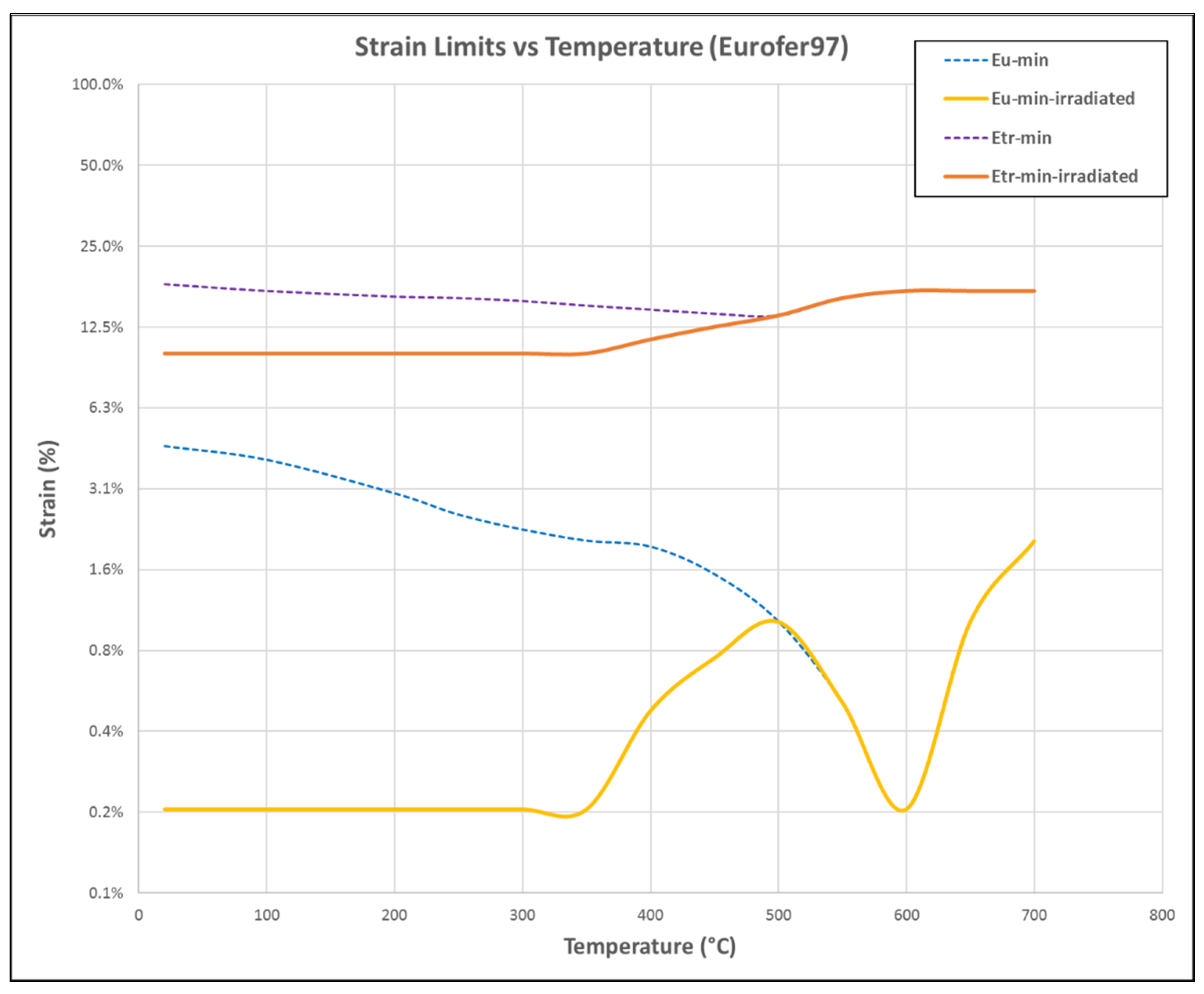
  • Material hardening behavior after the uniform strain point is not precisely known. Conventional uniaxial tension test data is affected by the necking at the uniform strain point and may not be valid after necking. Since Eurofer material has very low uniform strain even at unirradiated conditions, the hardening behavior at higher strains needed to be understood.
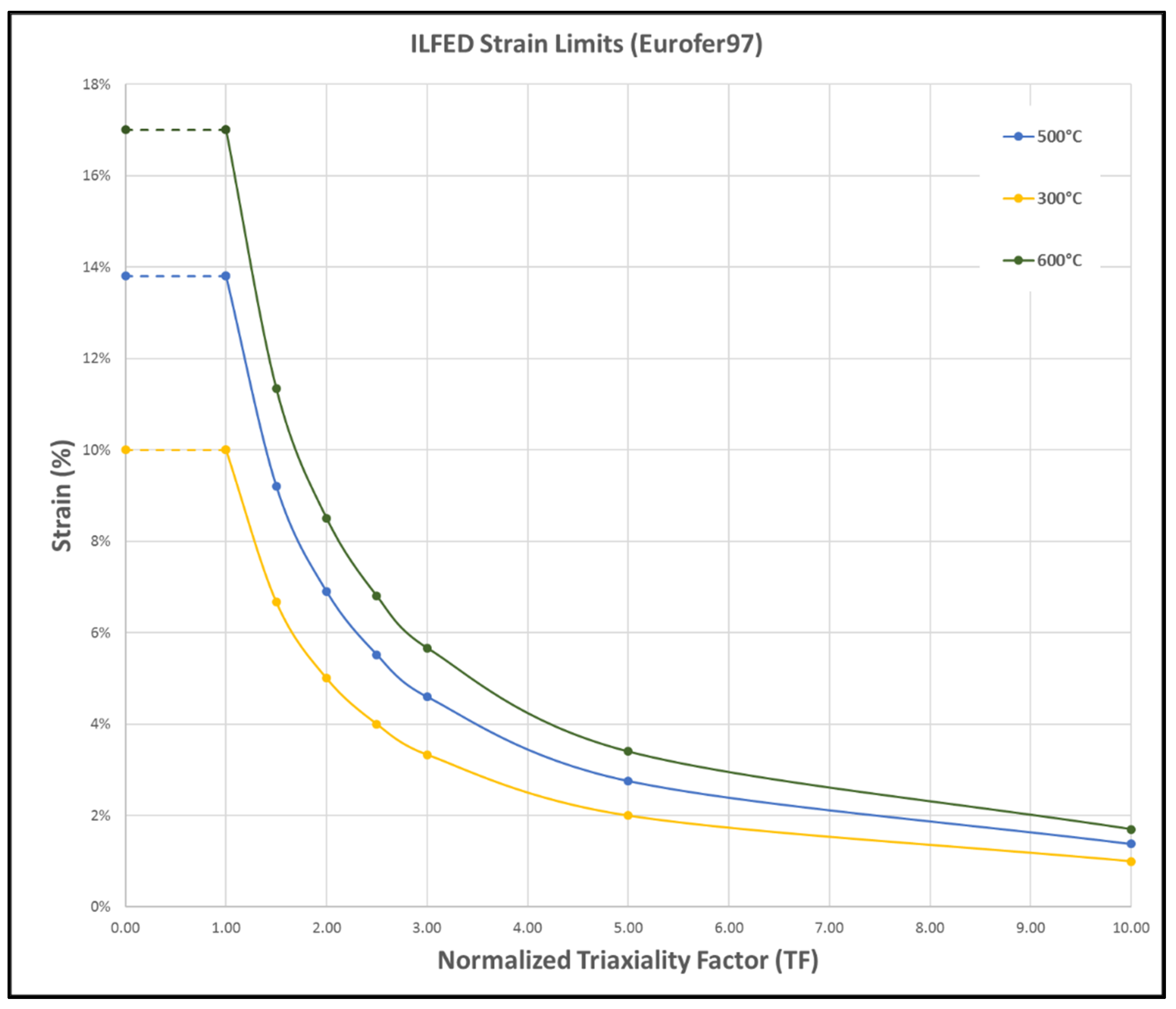
  • It is assumed that the failure strain–triaxial relationship for Eurofer is as represented in Figure 6, estimated from the equation for SDC-IC ILFED criteria. However, it is known that this equation may not properly represent the material failure dominated by void nucleation at low triaxiality values as opposed to the failure dominated by void growth at high triaxiality. Even at high triaxiality values, the relationship needs to be verified for Eurofer97 material.
  • As described in Section 2.4, the work here is performed using tensile stress–strain data at unirradiated conditions. Since at irradiated conditions, the yield stress and ultimate stress increases due to hardening, it is assumed that the unirradiated stress–strain curve is conservative. However, the plastic flow localization is an instability phenomenon and hence it could be affected by any change in the hardening behavior.
  • For the HCPB BB, component level tests under similar operating conditions (high secondary-thermal loads combined with relatively low primary loads) could be performed to validate the applicability of IPFL damage limits against the more relaxed ILFED damage limits.

Author Contributions

Conceptualization, A.R.; methodology, A.R., F.A.H. and G.Z.; software, A.R.; validation, F.A.H. and G.Z.; formal analysis, A.R.; investigation, A.R.; resources, F.A.H. and G.Z.; data curation, A.R.; writing—original draft preparation, A.R.; writing—review and editing, F.A.H. and G.Z.; visualization, A.R.; supervision, F.A.H. and G.Z.; project administration, F.A.H.; funding acquisition, F.A.H. All authors have read and agreed to the published version of the manuscript.

Funding

This work has been carried out within the framework of the EUROfusion Consortium and has received funding from the Euratom research and training program 2014–2018 and 2019–2020 under grant agreement No. 633053. The views and opinions expressed herein do not necessarily reflect those of the European Commission.

Institutional Review Board Statement

Not applicable.

Informed Consent Statement

Not applicable.

Data Availability Statement

The data are not publicly available due to ongoing research based on the current data.

Acknowledgments

The IT and hardware support from L. Freiner and the reviews and suggestions from H. Neuberger and F. Arbeiter at KIT-INR is gratefully acknowledged.

Conflicts of Interest

The authors declare no conflict of interest. The funders had no role in the design of the study; in the collection, analyses, or interpretation of data; in the writing of the manuscript, or in the decision to publish the results.

References

  1. Donné, A.J.H. The European Roadmap towards Fusion Electricity. Philos. Trans. R. Soc. Math. Phys. Eng. Sci. 2019, 377, 20170432. [Google Scholar] [CrossRef] [Green Version]
  2. Federici, G.; Boccaccini, L.V.; Cismondi, F.; Gasparotto, M.; Poitevin, Y.; Ricapito, I. An Overview of the EU Breeding Blanket Design Strategy as an Integral Part of the DEMO Design Effort. Fusion Eng. Des. 2019, 141, 30–42. [Google Scholar] [CrossRef]
  3. Raffray, A.R.; Calcagno, B.; Chappuis, P.; Fu, Z.; Furmanek, A.; Jiming, C.; Kim, D.-H.; Khomiakov, S.; Labusov, A.; Martin, A.; et al. The ITER Blanket System Design Challenge. Nucl. Fusion 2014, 54, 033004. [Google Scholar] [CrossRef] [Green Version]
  4. Hernández, F.A.; Pereslavtsev, P.; Zhou, G.; Kang, Q.; D’Amico, S.; Neuberger, H.; Boccaccini, L.V.; Kiss, B.; Nádasi, G.; Maqueda, L.; et al. Consolidated Design of the HCPB Breeding Blanket for the Pre-Conceptual Design Phase of the EU DEMO and Harmonization with the ITER HCPB TBM Program. Fusion Eng. Des. 2020, 157, 111614. [Google Scholar] [CrossRef]
  5. Cismondi, F.; Kecskes, S.; Aiello, G. HCPB TBM Thermo Mechanical Design: Assessment with Respect Codes and Standards and DEMO Relevancy. Fusion Eng. Des. 2011, 86, 2228–2232. [Google Scholar] [CrossRef]
  6. Hernández, F.; Cismondi, F.; Kiss, B. Thermo-Mechanical Analyses and Assessment with Respect to the Design Codes and Standards of the HCPB-TBM Breeder Unit. Fusion Eng. Des. 2012, 87, 1111–1117. [Google Scholar] [CrossRef]
  7. Zhou, G.; Hernández, F.; Boccaccini, L.V.; Chen, H.; Ye, M.Y. Preliminary Structural Analysis of the New HCPB Blanket for EU DEMO Reactor. Int. J. Hydrog. Energy 2016, 41, 7053–7058. [Google Scholar] [CrossRef]
  8. Zhou, G.; Hernández, F.; Boccaccini, L.V.; Chen, H.; Ye, M.Y. Preliminary Steady State and Transient Thermal Analysis of the New HCPB Blanket for EU DEMO Reactor. Int. J. Hydrog. Energy 2016, 41, 7047–7052. [Google Scholar] [CrossRef]
  9. Hernández, F.; Pereslavtsev, P.; Kang, Q.; Norajitra, P.; Kiss, B.; Nádasi, G.; Bitz, O. A New HCPB Breeding Blanket for the EU DEMO: Evolution, Rationale and Preliminary Performances. Fusion Eng. Des. 2017, 124, 882–886. [Google Scholar] [CrossRef]
  10. Zhou, G.; Hernández, F.; Boccaccini, L.V.; Chen, H.; Ye, M. Design Study on the New EU DEMO HCPB Breeding Blanket: Thermal Analysis. Prog. Nucl. Energy 2017, 98, 167–176. [Google Scholar] [CrossRef]
  11. Zhou, G.; Hernández, F.A.; Zeile, C.; Maione, I.A. Transient Thermal Analysis and Structural Assessment of an Ex-Vessel LOCA Event on the EU DEMO HCPB Breeding Blanket and the Attachment System. Fusion Eng. Des. 2018, 136, 34–41. [Google Scholar] [CrossRef] [Green Version]
  12. Zeile, C.; Hernández, F.A.; Maione, I.A.; Zhou, G.; Bachmann, C. Structural Assessment of the HCPB Breeding Blanket Segments in the EU DEMO Reactor under Normal Operation and a Central Plasma Disruption. Fusion Eng. Des. 2018, 136, 335–339. [Google Scholar] [CrossRef]
  13. Hernández, F.; Arbeiter, F.; Boccaccini, L.V.; Bubelis, E.; Chakin, V.; Cristescu, I.; Ghidersa, B.-E.; Gonzalez, M.; Hering, W.; Hernandez, T.; et al. Overview of the HCPB Research Activities in EUROfusion. IEEE Trans. Plasma Sci. 2018, 46, 2247–2261. [Google Scholar] [CrossRef]
  14. Zhou, G.; Hernández, F.; Zeile, C. A Methodology for Thermo-Mechanical Assessment of in-Box LOCA Events on Fusion Blankets and Its Application to EU DEMO HCPB Breeding Blanket. Kerntechnik 2018, 83, 256–260. [Google Scholar] [CrossRef] [Green Version]
  15. Aktaa, J.; Kecskés, S.; Cismondi, F. Non-Linear Failure Analysis of HCPB Test Blanket Module. Fusion Eng. Des. 2012, 87, 1085–1090. [Google Scholar] [CrossRef]
  16. Aktaa, J.; Kecskés, S.; Pereslavtsev, P.; Fischer, U.; Boccaccini, L.V. Non-Linear Failure Analysis of HCPB Blanket for DEMO Taking into Account High Dose Irradiation. Fusion Eng. Des. 2014, 89, 1664–1668. [Google Scholar] [CrossRef]
  17. Aktaa, J.; Carin, Y.; Vallory, J. Non-Linear Assessment of Critical Failure Modes in the First Wall of the European TBM. Fusion Eng. Des. 2018, 128, 223–230. [Google Scholar] [CrossRef] [Green Version]
  18. Jin, X.Z. Preliminary Safety Analysis of LOCAs in One EU DEMO HCPB Blanket Module. Fusion Eng. Des. 2017, 124, 1233–1236. [Google Scholar] [CrossRef]
  19. Stonehouse, M.; Seipp, T.G.; Kanamaru, S.; Morrison, S. A Novel Comparison of Design-by-Analysis Methods. J. Press. Vessel. Technol. 2012, 134, 054502-1–054502-4. [Google Scholar] [CrossRef]
  20. Zhu, X.-K. Strength Criteria Versus Plastic Flow Criteria Used in Pressure Vessel Design and Analysis. J. Press. Vessel. Technol. 2016, 138, 041402-1–041402-7. [Google Scholar] [CrossRef]
  21. Fursdon, M.; You, J.-H.; Li, M. Towards Reliable Design-by-Analysis for Divertor Plasma Facing Components—Guidelines for Inelastic Assessment (Part 1: Unirradiated). Fusion Eng. Des. 2019, 147, 111234. [Google Scholar] [CrossRef]
  22. Fursdon, M.; You, J.-H.; Barrett, T.; Li, M. A Hybrid Analysis Procedure Enabling Elastic Design Rule Assessment of Monoblock-Type Divertor Components. Fusion Eng. Des. 2018, 135, 154–164. [Google Scholar] [CrossRef] [Green Version]
  23. AFCEN. RCC-MRx 2012: Design and Construction Rules for Mechanical Components of Nuclear Installations. Addenda Included; AFCEN: Courbevoie, France, 2013. [Google Scholar]
  24. ITER. SDC-IC: Structural Design Criteria for In-vessel Components; ITER: Saint-Paul-lès-Durance, France, 2012. [Google Scholar]
  25. Aiello, G.; Aktaa, J.; Cismondi, F.; Rampal, G.; Salavy, J.-F.; Tavassoli, F. Assessment of Design Limits and Criteria Requirements for Eurofer Structures in TBM Components. J. Nucl. Mater. 2011, 414, 53–68. [Google Scholar] [CrossRef]
Figure 1. HCPB BB concept within the DEMO tokamak.
Applsci 11 09104 g001
Figure 2. (a) HCPB BB cap region with highlighted symmetry section. (b) Symmetry section considered for simulation.
Applsci 11 09104 g002
Figure 3. Static-structural analysis domain and boundary conditions.
Applsci 11 09104 g003
Figure 4. Stress limits with respect to temperature for Eurofer97 material.
Applsci 11 09104 g004
Figure 5. Strain limits with respect to temperature for Eurofer97 material.
Applsci 11 09104 g005
Figure 6. ILFED strain limits with respect to the triaxiality factor.
Applsci 11 09104 g006
Figure 7. Temperature distribution (a) on the whole BB cap region, and (b) on Eurofer97 structures.
Applsci 11 09104 g007
Figure 8. Von Mises stress results contour on BB cap region—elastic analysis.
Applsci 11 09104 g008
Figure 9. Identified high stressed locations according to elastic assessment.
Applsci 11 09104 g009
Figure 10. Maximum principal strain contour on BB cap region—inelastic analysis.
Applsci 11 09104 g010
Figure 11. Stress triaxiality contour on BB cap region—inelastic analysis.
Applsci 11 09104 g011
Table 1. Assessment against IPFL and ILFED damage modes according to elastic criteria.
PartLoc.Taverage
(°C)
P L + Q L ¯
(MPa)
S e D
(MPa)
IPFL Margin
(%)
Tpoint
(°C)
P L + P b + Q ¯
(MPa)
S d D
(MPa)
ILFED Margin
(%)
Cap TopA4806828776%51421138846%
B4883928386%52119938248%
C46520129532%46630039825%
D4712762925%47430839422%
E38428232914%38631144430%
F5519424462%57210433068%
G51816726938%52423735433%
First WallA338740342Failed351801462Failed
B341569341Failed353584460Failed
C381576330Failed380585445Failed
D386573328Failed388598443Failed
E3973003247%40133943823%
F370443333Failed3704464501%
G390331327Failed39637844114%
H391341326Failed39735444120%
I495333279Failed4963593775%
J38427232917%39533844424%
Back PlateA51122927015%51424136434%
B52314926243%52416935452%
C51618726730%51625336030%
BSSA51621026721%51628436021%
B51422226817%51427636224%
Pressure TubesA4142993186%41436342915%
B441328306Failed44633341320%
C442316306Failed44632141322%
D40927332015%41029443132%
Breeder PinsA500920276Failed4991006373Failed
B517354266Failed517372359Failed
C517366266Failed517395359Failed
D516360267Failed515393360Failed
E518337265Failed5183483583%
F516436267Failed516451360Failed
G518285265Failed51830935814%
H509788271Failed508880366Failed
I506926273Failed5061015368Failed
Table 2. Assessment against IPFL and ILFED damage modes according to inelastic criteria.
PartLoc.Taverage
(°C)
( ε ˜ m ) p l
(%)
ε u 2
(%)
IPFL
Criteria
Margin
Tpoint
(°C)
( ε ˜ ) p l × T F
(%)
ε t r
(%)
ILFED Criteria Margin
Cap TopA4800.0005%0.4475%100%5140.01%14.60%100%
B4880.0010%0.4692%100%5210.02%14.83%100%
C4650.0010%0.4076%100%4660.00%13.00%100%
D4710.0001%0.4230%100%4740.00%13.26%100%
E3840.0000%0.1915%100%3860.00%10.76%100%
F5510.0000%0.2461%100%5720.00%16.38%100%
G5180.0000%0.4006%100%5240.00%14.92%100%
First WallA3380.5416%0.1000%Failed3510.84%10.16%92%
B3410.2048%0.1000%Failed3530.33%10.19%97%
C3810.2736%0.1815%Failed3800.34%10.63%97%
D3860.2676%0.1965%Failed3880.29%10.80%97%
E3970.0036%0.2245%98%4010.01%11.10%100%
F3700.0502%0.1534%67%3700.05%10.45%99%
G3900.0100%0.2065%95%3960.06%10.98%99%
H3910.0092%0.2091%96%3970.06%11.01%99%
I4950.0000%0.4870%100%4960.00%14.00%100%
J3840.0072%0.1895%96%3950.08%10.96%99%
Back PlateA5110.0000%0.4374%100%5140.00%14.60%100%
B5230.0000%0.3702%100%5240.00%14.92%100%
C5160.0000%0.4108%100%5160.00%14.66%100%
BSSA5160.0000%0.4084%100%5160.00%14.66%100%
B5140.0000%0.4197%100%5140.00%14.60%100%
Pressure TubesA4140.0060%0.2706%98%4140.04%11.43%100%
B4410.0014%0.3436%100%4460.01%12.36%100%
C4420.0000%0.3456%100%4460.00%12.36%100%
D4090.0012%0.2581%100%4100.01%11.33%100%
Breeder PinsA5000.3824%0.4993%23%4990.42%14.10%97%
B5170.1057%0.4028%74%5170.13%14.69%99%
C5170.2214%0.4020%45%5170.28%14.69%98%
D5160.0655%0.4108%84%5150.08%14.63%99%
E5180.0913%0.3978%77%5180.10%14.73%99%
F5160.1854%0.4094%55%5160.19%14.66%99%
G5180.0000%0.3973%100%5180.00%14.73%100%
H5090.2996%0.4487%33%5080.32%14.40%98%
I5060.4854%0.4626%Failed5060.50%14.33%97%
Publisher’s Note: MDPI stays neutral with regard to jurisdictional claims in published maps and institutional affiliations.

