Article

Computational Model Development for Hybrid Tilting Pad Journal Bearings Lubricated with Supercritical Carbon Dioxide

1
Department of Mechanics and Design, Kookmin University, Seoul 02707, Korea
2
School of Mechanical Engineering, Kookmin University, Seoul 02707, Korea
*
Author to whom correspondence should be addressed.
Appl. Sci. 2022, 12(3), 1320; https://doi.org/10.3390/app12031320
Submission received: 19 November 2021 / Revised: 17 January 2022 / Accepted: 21 January 2022 / Published: 26 January 2022
(This article belongs to the Special Issue Advances in Fluid Film Bearings)

Abstract

:

Featured Application

Power generation systems based on supercritical carbon dioxide.

Abstract

Fluid film bearings lubricated with supercritical carbon dioxide (sCO2) eliminate the infrastructural requirement for oil lubricant supply and sealing in turbomachinery for sCO2 power systems. However, sCO2’s thermohydrodynamic properties, which depend on pressure and temperature, pose a challenge, particularly with computational model development for such bearings. This study develops a computational model for analyzing sCO2-lubricated tilting pad journal bearings (TPJBs) with external pressurization. Treating sCO2 as a real gas, the Reynolds equation for compressible turbulent flows solves the pressure distribution using the finite element method, and the Newton−Raphson method determines the static equilibrium position by simultaneously calculating forces, moments, flow rates of externally pressurized sCO2, and pressure drop due to flow inertia. The finite difference method solves the energy equation for temperature distribution. The density and viscosity of sCO2 are converged using the successive substitution method. The obtained predictions agree with the previous and authors’ computational fluid dynamics predictions, thus validating the developed model. Hybrid lubrication increases the minimum film thickness and stiffness up to 80% and 65%, respectively, and decreases the eccentricity ratio by up to 65% compared to those of pure hydrodynamic TPJB, indicating significant improvement in the load capacity. The bearing performance is further improved with increasing sCO2 supply pressure.

1. Introduction

The supercritical carbon dioxide (sCO2) cycle enables higher thermal efficiency than the conventional steam Rankine cycle, resulting in reduced fuel cost and greenhouse gas production [1]. Thus, the sCO2 cycle is extensively applied in various power-conversion systems, including concentrated solar thermal and nuclear power [2,3,4,5], waste heat recovery from large engines [6], and geothermal [1].
The high density of sCO2 at high-pressure can cause compact turbomachinery, critical equipment in circulatory systems for the sCO2 thermodynamic cycle, at low capital costs [2]. To achieve commercial viability, various types of bearings have been investigated to support the rotors of such high-speed turbomachinery.
Wright et al. [2] replaced angular contact ball bearings initially installed in a turbocompressor for the sCO2 Brayton cycle with gas-foil bearings (GFBs). The GFBs lubricated with sCO2, enabled a simple configuration without the sealing mechanism to prevent oil contamination and ensured a long bearing life. During preliminary tests, the authors found that high-pressure sCO2 in the foil thrust bearing generates significant power loss, which is attributed to the rotational speed. Cho et al. [7] employed GFBs to support the shaft in their 10-kWe-class unrecuperated sCO2 Brayton cycle [7]. Preliminary operations were successfully conducted at 30 krpm and at a turbine inlet temperature and pressure of 83 °C and 8500 kPa, respectively. Cho et al. [8] also reported a 60-kWe-class recuperated Brayton cycle facility with turbomachinery supported on oil-lubricated tilting-pad bearings. To prevent oil contamination of the process fluid (sCO2), carbon ring-type mechanical seals are fixed between the turbine and the bearing unit, resulting in a long shaft. The above-cited studies focused on cycle analysis rather than the constituents. Although Ahn et al. [9] and Utamura et al. [10] studied the design of the experimental loop for sCO2 power cycles, they did not detail the bearings employed for turbomachinery.
To achieve the desired performance of turbomachinery for sCO2 power cycles, the performance of their bearings is an important design consideration [10]. Thus, researchers have developed computational models to predict the performance of various types of sCO2-lubricated bearings. Conboy [11] used an isothermal and real gas model to investigate the static performance of a sCO2-lubricated gas-foil thrust bearing (GFTB). The author used the thermodynamic properties of sCO2 reported in Ref. [12] and showed that GFTB has a larger load capacity and power loss when lubricated with sCO2 than with air. Qin et al. [13,14] investigated the static performance of sCO2-lubricated GFTBs using computational fluid dynamics (CFD). Dousti and Allaire [15] studied a plain sCO2-lubricated journal bearing using a density model linearized with pressure. The isothermal model considers pressure-dependent density on only the Reynolds equation’s left-hand side (Poiseuille terms). The overly simplified compressible model predicted a greater load capacity of the bearing than did the incompressible model. Heshmat et al. [16] assumed sCO2 as an isothermal ideal gas and analyzed a gas-foil journal bearing (GFJB) with the same diameter and length as the journal bearing reported in Ref. [15]. The authors predicted a comparable load capacity of GFJB for the plain journal bearing. In addition, they reported that the load capacity obtained using the compressible model is higher than that obtained using the incompressible model, which is inconsistent with the results reported in Ref. [15]. Dimond and Allaire [17] studied sCO2-lubricated tilting pad journal bearings (TPJBs). The predictive model neglects the most crucial parameters associated with sCO2, such as the density and viscosity dependency on pressure and temperature. The authors compared oil- and sCO2-lubricated TPJBs and discovered that using sCO2 as a TPJB lubricant requires increased bearing size to have dynamic coefficients comparable to those of oil-lubricated TPJBs. Xu and Kim [18] developed a thermoelastohydrodynamic model for CO2-lubricated externally pressurized GFTB. The lubricant, CO2, was treated as a real gas. The authors compared laminar and turbulent flow models for CO2- and R245fa-lubricated bearings. Preuss [19] analyzed hybrid journal and thrust bearings lubricated with sCO2 and calculated the load capacity using the rule of thumb. To calculate the rotordynamic coefficients, the author used a commercial tool developed by San Andres and Childs [20] for water-lubricated journal bearings and reported that the stiffness coefficient increases with an increase in the bearing diameter for angled injection hybrid journal bearing. Chunxiao et al. [21] reported a detailed dynamic analysis of sCO2-lubricated plain journal bearings. The turbulent flow model employs the look-up table method to extract the thermodynamic properties of sCO2 in Ref. [12], similar to that in Ref. [11]. Kim et al. [22] conducted theoretical and experimental studies on the rotor dynamic instability of magnetic journal bearings operating in an sCO2 ambiance. To understand the unstable shaft levitation at high speeds, sCO2 pressure forces developed between the shaft and the magnetic bearings were calculated using the one-dimensional Reynolds equation.
Herein, we developed a computational model for hybrid (hydrostatic/hydrodynamic) TPJB lubricated with sCO2 and predict its static and dynamic performances. In the hybrid TPJB, pressurized sCO2 is supplied through a hole located at the center of the pad’s recess to enhance the load capacity and dynamic characteristics, as reported for water- and air-lubricated bearings [20,23,24]. The Reynolds equation for turbulent compressible fluid flows solves hydrodynamic pressure generation. The mass flow balance between the orifice flow and the Poiseuille and Couette flows at the pad recess boundaries calculates the recess pressure. The fluid inertia effects at the recess boundaries, which cause a pressure drop, were modeled using the average velocities of film flows. The real gas model is used for sCO2, whose thermophysical properties are functions of pressure and temperature.

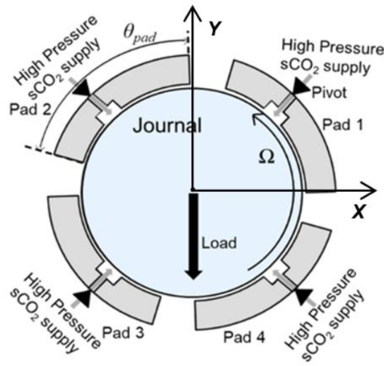
2. Hybrid TPJB Lubricated with sCO2 and Its Computational Model

Figure 1 shows a schematic of TPJB with four pads and an angular extent of θpad in the load-between-pad (LBP) configuration. Each pad has a rectangular recess with a hole at its geometric center to supply pressurized sCO2 through the pivot support. The supplied sCO2 flows into the gap between the rotating journal and the pads.

2.1. Thermohydrodynamic Model for Turbulent Compressible Fluid Flows

The Reynolds equation for turbulent and compressible fluid flows governs pressure distribution in the film land area. Note that sCO2 is a highly compressible fluid, and its large density and low viscosity result in a large Reynolds number:
x G x ρ h 3 μ p x + z G z ρ h 3 μ p z = U 2 ρ h x + ρ h t
where ρ, h, µ, p, U, t, x, and z denote the lubricant density, film thickness, viscosity, pressure, journal surface speed, time, circumferential coordinate, and axial coordinate, respectively. Gx and Gz are the turbulent coefficients empirically determined using the Hirs bulk flow model [25], which considers the inertia effects inherent to the flow turbulence:
G x = 1 2 + m 0 G z ,   G z = 2 1 + m 0 n 0 R e - ( 1 + m 0 )
where m0 (=−0.25) and n0 (=0.066) are empirical constants applicable exclusively to smooth surfaces. Re is the local flow Reynolds number dependent on the local density ρ, viscosity µ, and film thickness h:
R e = ρ U h μ
The flow becomes turbulent when Re is greater than or equal to the critical Reynolds number Rec, which is equal to 1000 [15,26,27]. For Re less than the critical value, Gx and Gz are equal to 1/12 for the laminar flow.
The equation of film thickness is modified from that in Ref. [28] by including the recess depth Dr to account for the depth of the recess:
h = C p + e cos θ c θ r p ζ cos θ θ p δ R p + t p sin θ θ p + D r
where Cp (=RpRj), e, θc, θ, rp (=RpRb), ζ, θp, δ, tp, and Dr are the pad radial clearance, journal eccentricity, angle between the line passing through the bearing and journal centers and the horizontal axis X, circumferential coordinate starting from the axis X, preload, pivot deflection, pivot circumferential location, pad tilt angle, pad thickness, and depth of the recess, respectively. Rp, Rb, and Rj are the pad, bearing, and journal radii, respectively. The mathematical model for the pivot deflection ζ is detailed in Refs. [28,29,30]. Note that Dr is null at the film land region.
In the recess region, externally pressurized sCO2 with pressure ps is provided through the orifice restrictor, causing a pressure drop from ps to pre, which then flows over the land area on each pad’s surface. The gaseous mass flow rate through the orifice restrictor Qo for the choked and unchoked conditions are derived from the Bernoulli’s equation considering mechanical energy balance between two arbitrary points on a streamline. The relations for both choked and unchoked conditions can be given from [18,31] as follows:
Un - choked :   p r e p s > 2 κ + 1 κ κ 1 Q o = C d A o R g T s 2 κ κ 1 p r e p s 2 κ p r e p s κ + 1 κ Choked :   p r e p s 2 κ + 1 κ κ 1 Q o = C d A o R g T s 2 κ κ + 1 2 κ + 1 1 κ 1
where Cd, Ao, Rg, and Ts are the discharge coefficient, orifice area, gas constant, and supply temperature, respectively, and κ is the ratio of the specific heat capacity at constant pressure cp to that at constant volume cv.
The mass flow balance between the orifice mass flow (Mo = ρQo) and Poiseuille and Couette flows at the recess’s circumferential leading (Γi) and trailing ( Γ i ) boundaries and axial leading (Γj) and trailing ( Γ j ) boundaries gives recess pressure (pre):
Γ i Γ i G x ρ h 3 μ p x ρ U h 2 d z + Γ j Γ j G z ρ h 3 μ p z d x = M o
The pressure drop due to inertia forces at the boundary edges of the recess is modeled based on Bernoulli type relationships [32,33]. These relationships were derived for step bearings by assuming inertia effect dependency on average velocity instead of local velocity. The equations for turbulent flows can be given as follows:
Circumferential direction:
p r e p d c = ρ 2 Q l 2 1 h l 2 1 h r e 2 + 0.412 ρ Q l 2 δ l h l 2 δ r e h r e 2 1.725 ρ V 2 β l β r e where   β = 0.885 R e 0.367 ,   δ = 1.95 R e 0.43 l : film   land ,   r e : recess
Axial direction:
p r e p d a = ρ 2 Q l 2 1 h l 2 1 h r e 2
where pdc and pda are the pressures at the entrances of the film land in the circumferential and axial directions, respectively. Ql, hl, and hre are the flux, film thickness at the land area, and film thickness at the recess area, respectively.
The numerical scheme to find the recess pressure (pre) and pressure drops (pre-pdc, pre-pda) at the entrance boundary of the film land for a given supply pressure (ps) is explained in the next section.
The energy equation calculates the temperature distribution T. In the energy equation, thermal energy transport due to fluid flow advection and heat convection into the bearing and journal surfaces balance the compression work and frictional power dissipation as follows [34]:
c p ( ρ h V T ) x + ( ρ h W T ) z + h t b T T b + h t j T T j = β t h T V p x + W p z + h U 2 p x + μ h 1 G x V 2 + W 2 + U 2 V + U G x U 4 V
where V and W are the bulk flow velocities in the circumferential and axial directions, respectively, and htb and htj are the convective heat transfer coefficients for the bearing surface at temperature Tb and journal at temperature Tj, respectively. βt is the volumetric expansion coefficient [34], which can be calculated using the following relation:
β t = 1 ρ ρ T ρ
Notably, βt is 0 for incompressible liquids and 1 for ideal gases. The thermal energy mixing model for the inlet flow between adjacent pads follows Ref. [28].

2.2. Real Gas Model for sCO2

CO2 is a real gas whose density and viscosity vary with temperature and pressure, particularly in the supercritical region. Therefore, the current study takes the density and viscosity models proposed by Wang et al. [35] and Fenghour and Wakeham [36], respectively, to predict the pressure and temperature-dependent density and viscosity of CO2.
The empirical model for calculating the density of CO2 is valid for pressure and temperature ranging from 3 to 60 MPa and from 303 to 473 K, respectively. The density can be expressed as follows:
ρ = a 1 T r 3 + a 2 T r 2 + a 3 T r + a 4 p r 6 + b 1 T r 3 + b 2 T r 2 + b 3 T r + b 4 p r 5 + c 1 T r 3 + c 2 T r 2 + c 3 T r + c 4 p r 4 + d 1 T r 3 + d 2 T r 2 + d 3 T r + d 4 p r 3 + e 1 T r 3 + e 2 T r 2 + e 3 T r + e 4 p r 2 + f 1 T r 3 + f 2 T r 2 + f 3 T r + f 4 p r + g 1 T r 3 + g 2 T r 2 + g 3 T r + g 4
where Tr (=T/Tc) and pr (=p/pc) are the ratios of the local temperature and pressure to the temperature and pressure at the critical point of CO2, respectively. Note that Tc = 304.1 K, and pc = 7.37 MPa. See Ref. [35] for the values of the coefficients (ai, …, gi, i = 1, …, 4). Note that the value of c4 is mistyped in Ref. [35] and the correct value is −23259.58953 [15].
The viscosity equation is also empirically derived, which models CO2 as a function of temperature and density:
μ = 1.00697 T G * T * + l 11 ρ + l 21 ρ 2 + l 61 ρ 6 T * 3 + l 81 ρ 8 + l 82 ρ 8 T * ln G * T * = n = 0 4 λ n ln T * n , T * = κ T ε , ε κ = 251.196
where T* is the reduced temperature. The coefficients l11, l21, l81, l82, and λn = 0…4 can be found in Ref. [36].

2.3. Boundary Conditions for Pressure and Temperature

The pressure at all the edges of the pad and the pad’s backside is equal to the ambient pressure pa. The recess pressure pre is constant throughout the recess region owing to the large recess depth relative to the film thickness in the land area [37]. The bearing and journal surface temperatures are set equal to the supply lubricant temperature [38]. The film flow temperature at the inlet of each pad is calculated using the thermal energy mixing model [28], which considers the mixture of the hot lubricant from the upstream pad with the cold (supplied) lubricant.

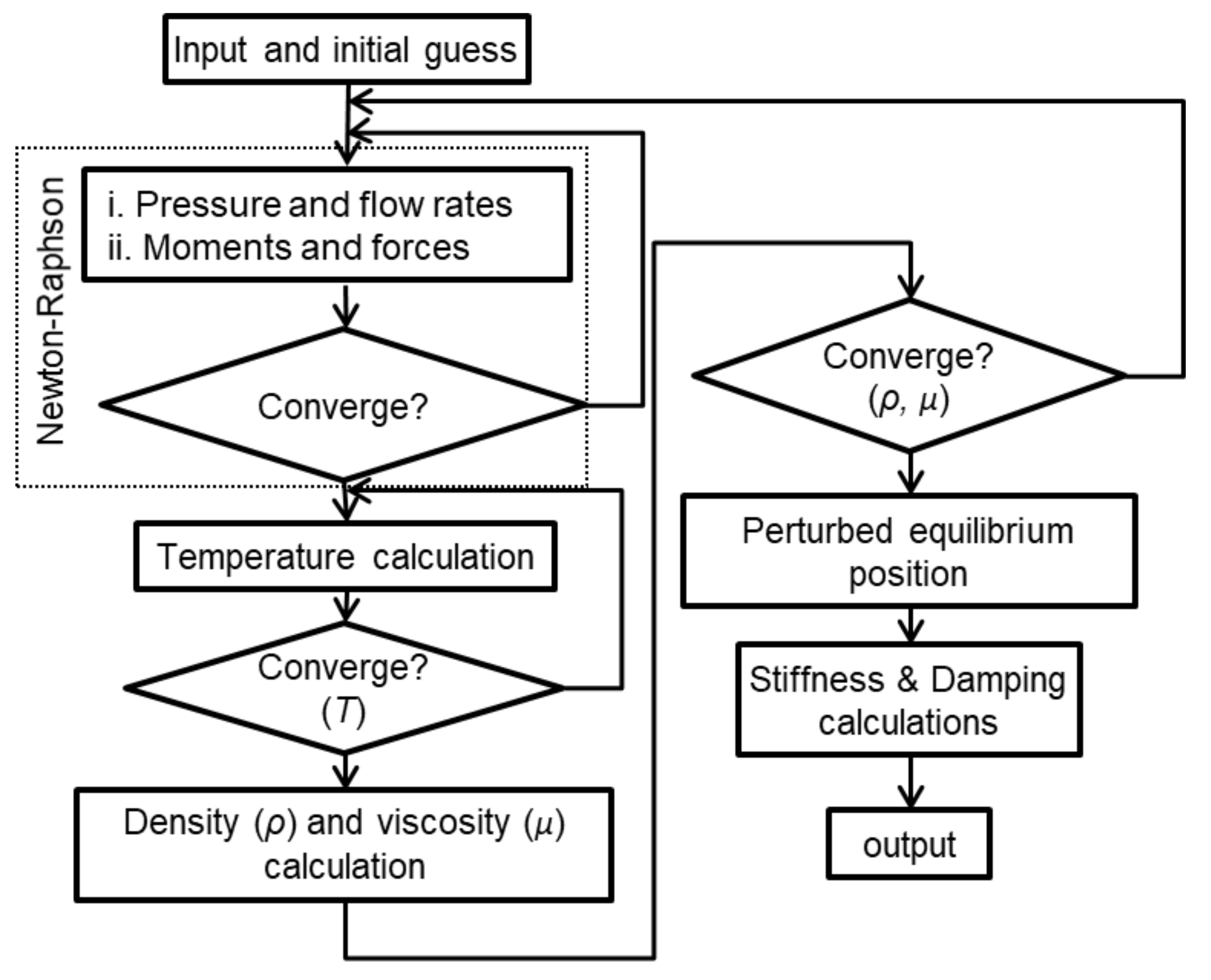
3. Numerical Procedure

The current computational model and numerical scheme are based on those for hydrodynamic TPJBs considering pivot stiffness in Ref. [28], which is extended further to consider hydrostatic pressurization at the recess region, flow turbulence, and pressure/temperature-dependent thermochemical properties of the lubricant (sCO2). The finite element method solves the Reynolds equation for pressure, the finite difference method solves the energy equation for the temperature distribution, and the Newton–Raphson method determines the equilibrium position. Figure 2 shows a flowchart of the numerical procedure.
Each step in Figure 2 is briefly explained as follows:
  • The bearing geometry, lubricant properties at the initial condition, the initial guesses for the pad tilting angle δ, pivot deflection ζ, eccentricity ratio ϵ, the angle between the X-axis and the line of the centers θc, and the pressure ratios pratio (pre/ps), pratiod (pdc/ps), pratioa (pda/ps) are provided as the input. For the initial guess for δ, Equation (4) assumes zero film thickness at the trailing edge of a pad, which indicates the maximum δ. Half of the maximum δ is then taken as the initial guess for δ of each pad. The initial guess for ζ is 0.1% of the bearing clearance. Similarly, the initial guess for ε, pratio, pratiod, and pratioa must be positive and less than 1, and θc is guessed to be 90°, indicating that the rotor is displaced only in the vertical direction.
  • The finite element method solves the Reynolds equation to compute the pressure distribution over each pad. The generated hydrodynamic pressure exerts a force Fpad on the surface of the pad, which deflects the supporting pivot and gives rise to a restoring force Fp in it [28]. As shown in Equation (13), TPJB with the number of pads Npad in the static equilibrium requires that Fp balance Fpad all the moments and bearing horizontal force FX balance to zero, the bearing vertical force FY balance the static load Fp0, and the orifice flow rate Qo balance the summation of the flow rates at the recess boundaries Qr. The circumferential and axial pressure drops at the recess edges due to inertia are also calculated iteratively as follows:
    F p a d F p n = 1 N p a d M 1 N p a d F X F Y F p 0 Q r + Q o n = 1 N p a d p d c i p d c i 1 n = 1 N p a d p d a i p d a i 1 n = 1 N p a d = 0 0 0 0 0 0 0
    where i and i − 1 denote the current and previous iterations, respectively. The Newton–Raphson method calculates the equilibrium position.
  • Once the static equilibrium position converges, the thermal energy mixing model calculates the fluid’s inlet temperature at the pad’s leading edge. The control-volume finite difference technique with an upwind scheme solves the two-dimensional energy equation (Equation (9)) for the temperature distribution (see Ref. [34] for more details).
  • The converged pressure and temperature are then used to calculate the density and viscosity.
  • Once the density and viscosity are converged iteratively using the successive substitution method, the journal is perturbed to a new position, and static equilibrium is achieved again.
  • The stiffness and damping coefficients are calculated from the ratio of the difference between the forces at the new and old equilibrium positions to the difference in distance and velocity, respectively, at both points. Note that the squeeze velocity term given on the right-hand side of the Reynolds equation accommodates the calculation of stiffness and damping coefficients.

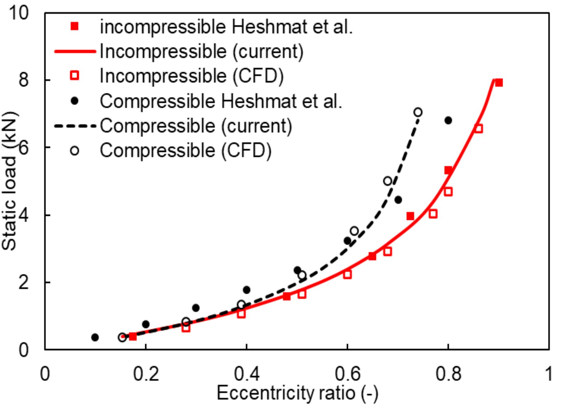
4. Model Validations

The experimental and theoretical performance of hybrid TPJBs lubricated with SCO2 has not yet been reported. Therefore, we performed comprehensive model validations by comparing the obtained model predictions to the reported predictions or test data available in the literature for density and viscosity models of SCO2, load-carrying performance of SCO2-lubricated hydrodynamic journal bearings, and the load-carrying performance of a multi-recess hybrid journal bearing lubricated with low viscosity fluid, including water, operating with significant flow turbulence.

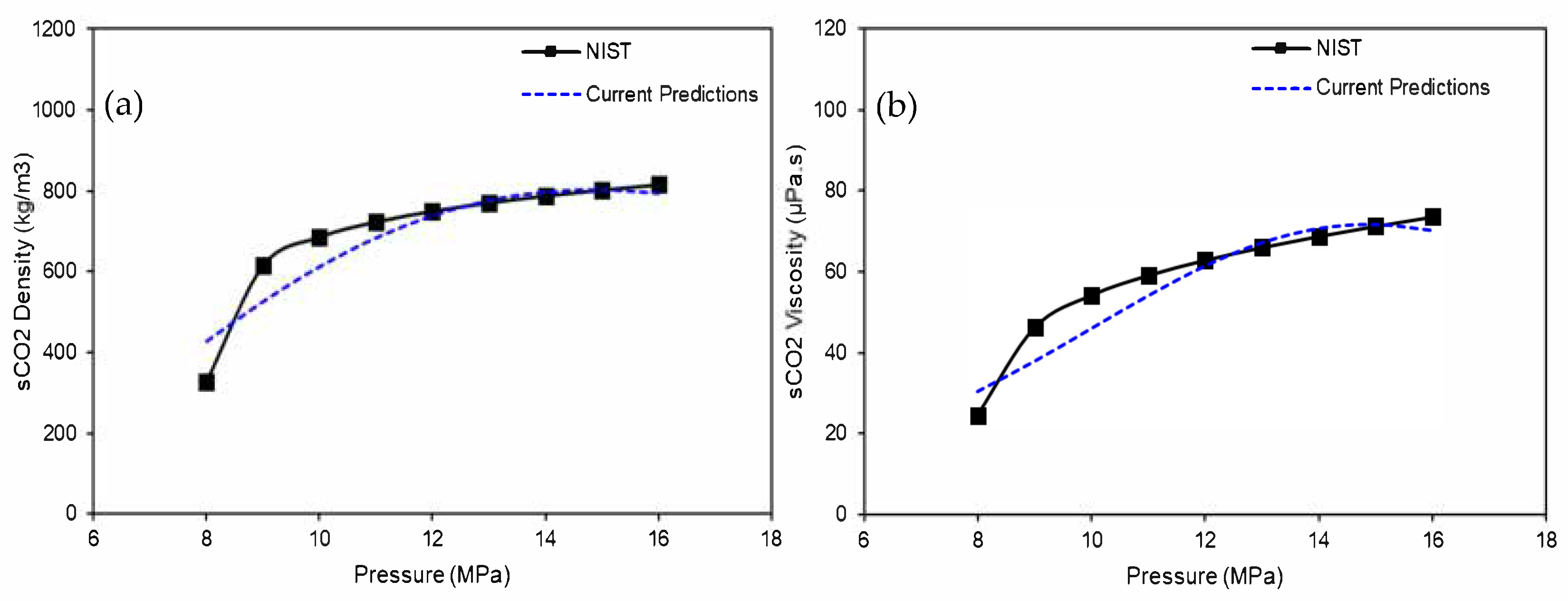
4.1. Density and Viscosity of sCO2

Figure 3 compares (a) density and (b) viscosity predictions plotted against pressure at a temperature of 37℃ to the predictions from National Institute of Standards and Technology (NIST) [12]. Note that the predicted data from NIST are the most reliable for bearing lubrication models [11,21]. Both density and viscosity increase nonlinearly with an increase in pressure. The density and viscosity calculated using Equations (11) and (12), respectively, agree well with the predictions in Ref. [12].

4.2. Fixed-Pad Hydrodynamic Journal Bearings

Figure 4 compares the predicted static load versus eccentricity ratio for an sCO2-lubricated plain journal bearing to the predictions in Ref. [16] with incompressible and compressible fluid flows. The analyzed bearing has an axial length and a diameter of 40 mm (L/D = 1) with a radial clearance of 40 µm, and the rotating speed is 60 krpm [16]. CFD model predictions using ANSYS FLUENT software are also compared with both predictions. In the CFD model, the ANSYS design modeler is used to create the fluid film model. The fluid film is meshed with 10 divisions in the radial direction and 900 divisions in the circumferential direction, and it has an element face size of 0.4 mm in the axial direction, resulting in 900,000 hexahedron elements. The interfaces attached to the bearing and journal sides are specified as stationary and rotating no-slip walls, respectively. Three-dimensional (3D) compressible Reynolds-averaged Navier–Stokes (RANS) with an SST k-omega turbulence model is solved using a coupled numerical scheme until the predefined convergence criteria are reached. Note that the CFD tool also uses Equations (11) and (12) to model the density and viscosity of sCO2, respectively. The static load increases nonlinearly with the eccentricity ratio for all predictions. Compressible fluid flow models show higher load capacity than the incompressible ones, particularly for high eccentricity ratios, because the density and viscosity of compressible fluids (sCO2) increase with an increase in hydrodynamic pressure under heavy loads (Figure 3). The current bulk flow model predictions agree well with those obtained using CFD. For the compressible fluid flow model, the discrepancies between the current model predictions and those reported in Ref. [16] can be attributed to the difference in the density and viscosity models. Reference [16] treats sCO2 as an isoviscous ideal gas, whereas the proposed model considers it a real gas with temperature- and density-dependent viscosity. The mean square errors for the current predictions and those in Ref. [16] are 0.13% and 0.35% for incompressible and compressible fluids, respectively.

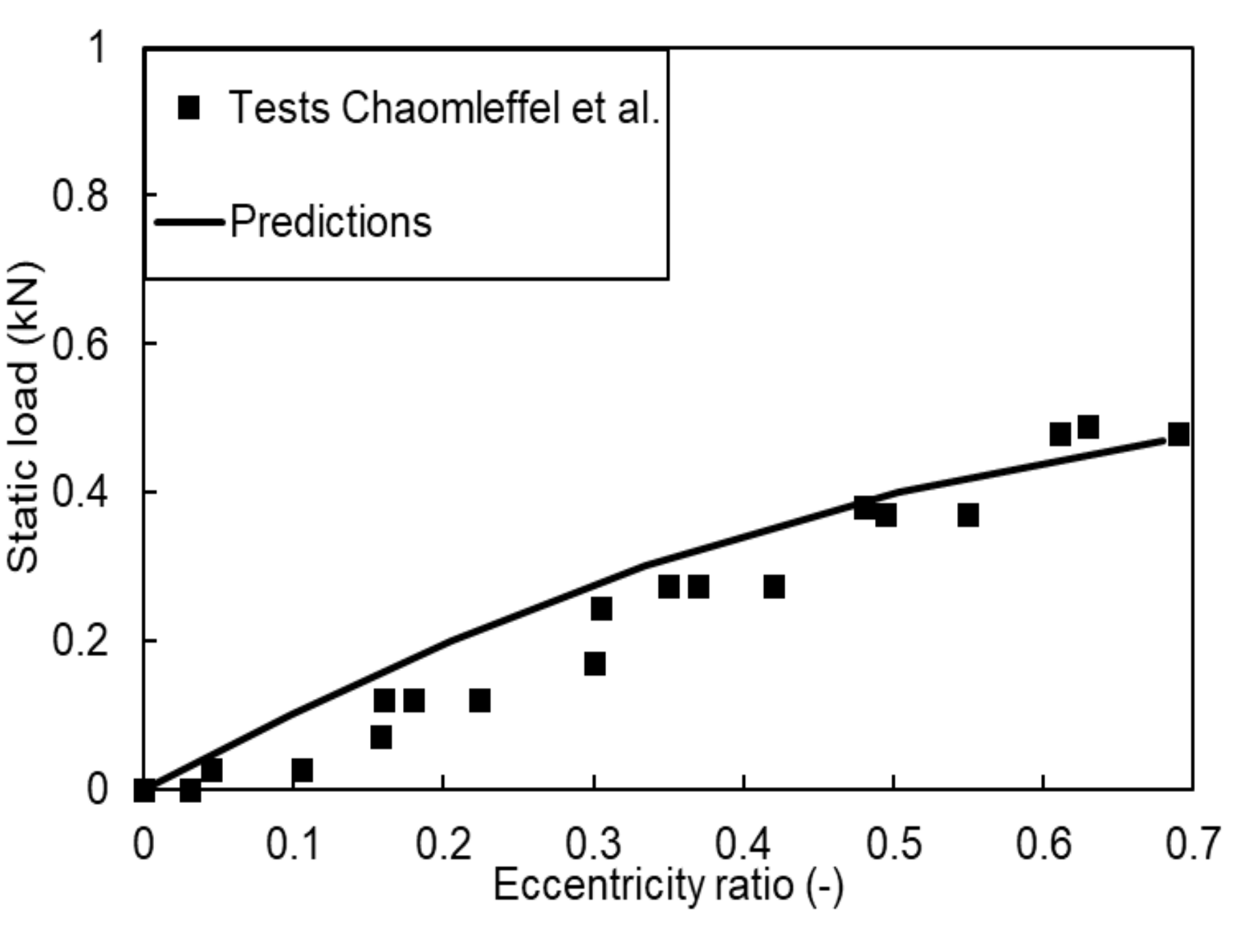
4.3. Fixed-Pad Hydrostatic and Hybrid Journal Bearings
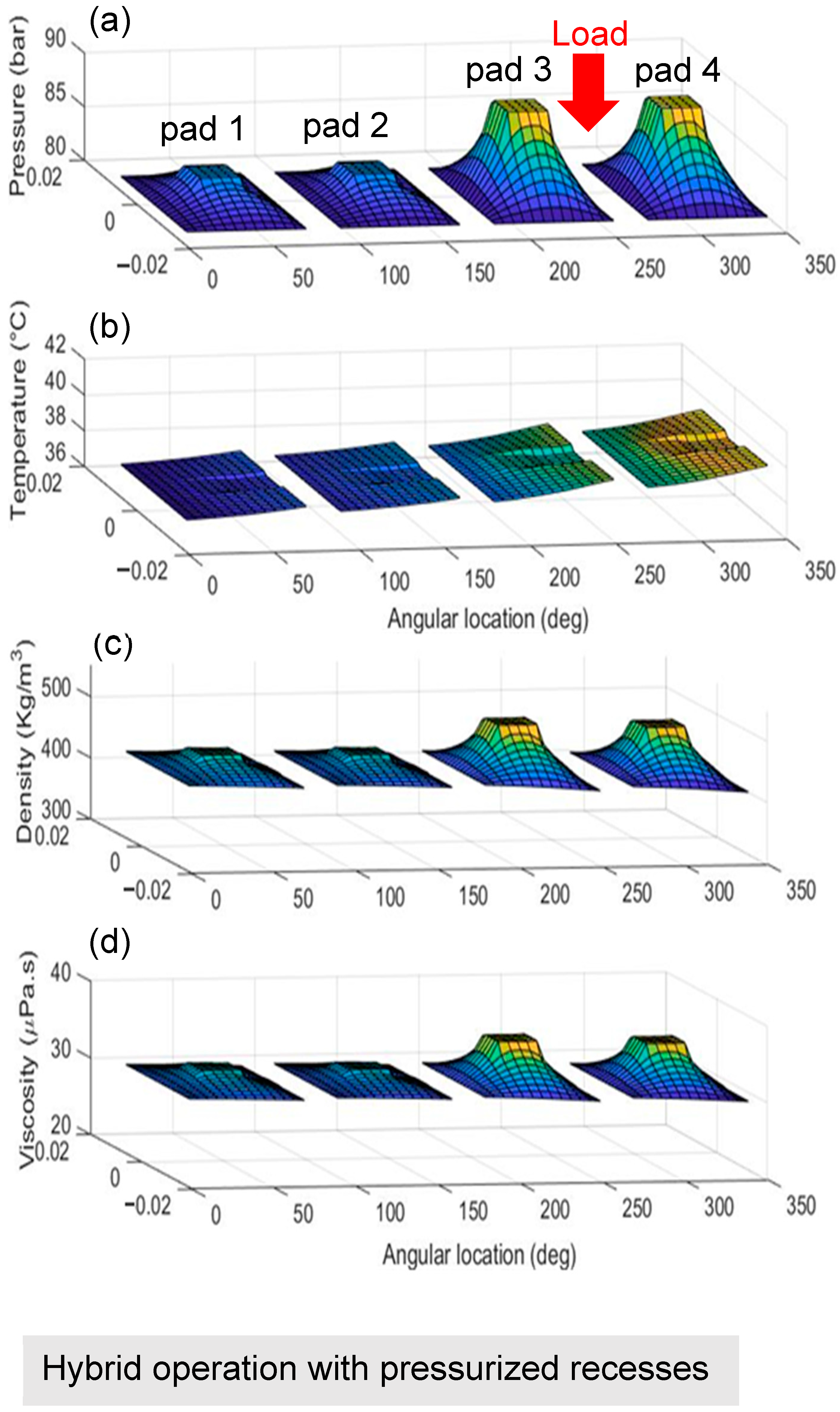
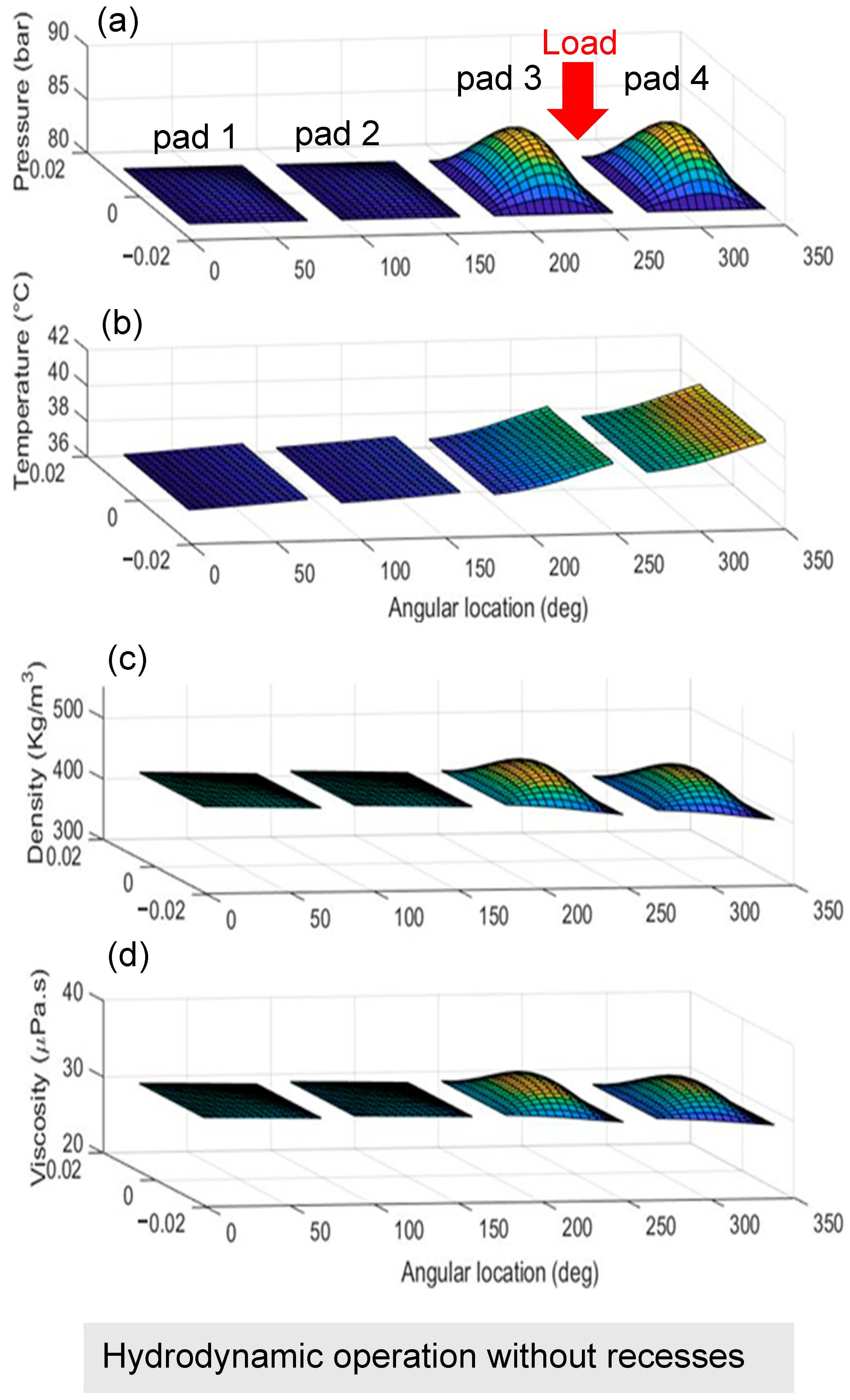
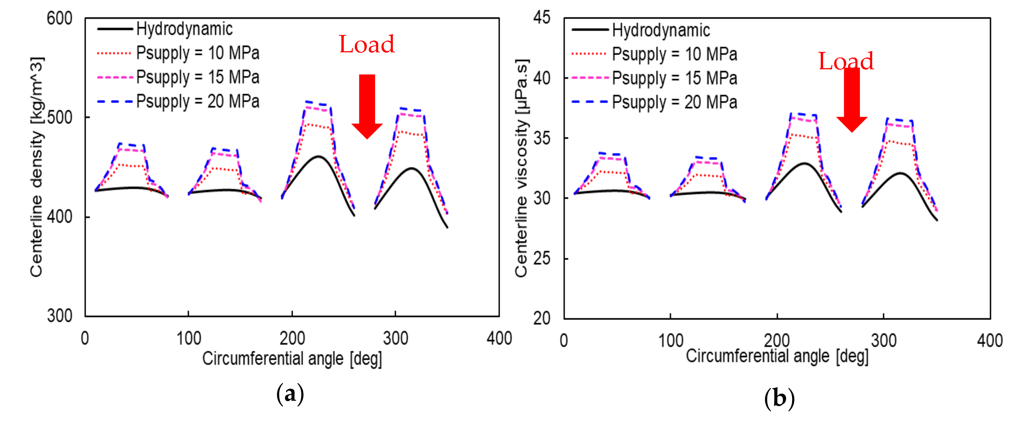
The test data for the water-lubricated, three-recess hybrid fixed-pad journal bearing reported in Ref. [39] validate the proposed bulk flow model for hydrostatic/hydrodynamic hybrid operations. The analyzed bearing has an axial length and a diameter of 80 mm (L/D = 1) with a radial clearance of 125 µm. The circumferential angle and width of the recess are 90° and 50 mm, respectively, and the recess depth is 10 mm [39]. The low viscosity of water may lead to flow turbulence at high operating speeds and significant fluid inertia at recess edges. Figure 5 compares the predicted static load plotted against the eccentricity ratio with the test data from Ref. [39] at 0 rpm, i.e., pure hydrostatic operation. In general, the predictions agree well with the test data, with a mean square error of 0.3%.
Figure 6 shows the predicted centerline pressure ratio (P/Ps) compared to the test data from Ref. [39] at rotor speeds of 5 and 8 krpm with a static load of 356 N applied at 270°. Note that the figure shows one-third of the bearing geometry and film pressure between two externally pressurized flow supply tubes located circumferentially at 210° and 330°. The predicted pressure ratios are compared to test data measured at 11 locations from 210° to 310° with an increment of 10°. The film pressure ratio is higher at the recess regions. The sudden pressure drop at the entrance of the film land is attributed to the increase in the flow inertia with an increase in rotor speed. The predictions agree well with test data with mean square errors of 0.04% and 0.05% for 5- and 8-krpm rotor speeds, respectively, thus validating the proposed bearing model for hybrid operations.

5. Results

Table 1 lists TPJB, pivot, and recess geometries and the properties of sCO2 at the initial condition. The journal diameter and axial pad length are both equal to 25 mm. The four pads, each with an angular extent of 70°, a pad thickness of 8 mm, a pivot offset of 0.5, and a preload factor of 0.5, constitute the TPJB. The pivot is of the rocker-back shape, a cylindrical type whose radius is 18 mm with a housing radius of 21 mm. The rocker-back pivot length is equal to the bearing length (25 mm). Each pad has a rectangular recess whose geometrical center is concentric with the pad’s pivot. The recess has a circumferential length of 5 mm (22.9°), an axial length of 5 mm, and a depth of 0.1 mm, thus covering about 6.67% of the pad area. The orifice at the center of the recess has a diameter of 0.5 mm, and the orifice discharge coefficient is 0.68 [31]. The bearing is lubricated with sCO2 with an ambient pressure and temperature of 8.0 MPa and 37 °C, respectively, at which its density and viscosity are 426.6 kg/m3 and 30.4 μPa·s, respectively. The temperature of the high-pressure sCO2 supplied through the orifice is similar to that of the ambiance. Note that sCO2 supplied through the orifice must have a higher pressure than the ambient pressure to pressurize the bearing hydrostatically.
Figure 7 shows plots of the 3D distributions of the (a) pressure, (b) temperature, (c) density, and (d) viscosity of the lubricant (sCO2) over each pad for hybrid TPJB with pressurized recesses. The supply pressure of sCO2 at the orifice is 10 MPa, and the static load applied at 270° and rotor speed are 100 N and 60 krpm, respectively. Each pad has peak constant pressure at the recess region. The loaded pads (pads 3 and 4) have the highest recess pressure, whereas the unloaded pads (pads 1 and 2) have the lowest values. The temperature is lowest at the pad leading edge and highest at the trailing edge. For each pad, the stepped track from the recess toward the trailing edge is attributed to the cooling effect of the fresh orifice flow. The density and viscosity of sCO2 are maximum at the recess region. The loaded pads (pads 3 and 4) have the highest values, whereas the unloaded pads (pads 1 and 2) have the lowest values, similar to the case of pressure. Though the density and viscosity of sCO2 are functions of both pressure and temperature, it mainly follows the trend of the film pressure, as the temperature rise is relatively insignificant owing to the large specific heat of the lubricant.
Figure 8 shows the 3D distributions of (a) pressure, (b) temperature, (c) density, and (d) viscosity of sCO2 over pads for conventional hydrodynamic TPJB without recesses but with a load and speed similar to those in Figure 7. The loaded pads (pads 3 and 4) have the highest hydrodynamic pressure, whereas the unloaded pads (pads 1 and 2) have the lowest pressure. Note the relatively small film pressure on the unloaded pads for the hydrodynamic TPJB compared to that of hybrid TPJB. The film temperature rises from the lowest value at the leading edge of the unloaded pad (pad 1) to the maximum value at the trailing edge of the loaded pad (pad 4). Note that hydrodynamic TPJB has a higher temperature than hybrid TPJB, particularly at the loaded pads; the hydrostatically pressurized fresh fluid flow from the orifice cools the film for hybrid TPJB. Temperature changes in the axial direction are relatively insignificant, as in hybrid TPJBs.
Figure 9 shows the centerline (a) film thickness, (b) pressure, and (c) temperature plotted against the circumferential coordinate for the supply pressures of 10, 15, and 20 MPa for the hybrid TPJB with a static load of 100 N and rotor speed of 60 krpm. The predictions for the hydrodynamic TPJB without recesses are also presented for comparison purposes. Note that the large film thickness at the recess area for hybrid TPJBs is due to the recess depth of 0.1 mm. The film thickness for hybrid TPJBs is larger than that for the hydrodynamic TPJB at the loaded pads, and it increases with an increase in supply pressure. The centerline pressure for the hybrid TPJB is also greater than that of the hydrodynamic TPJB and increases with an increase in the supply pressure for both loaded and unloaded pads. The pressure drop is attributed to the inertia effects at the boundary edges of the recess, as experimentally obtained in Ref. [39]. The pad tilting angle, pivot radial deflection, and maximum pivot stress for different supply pressures are provided in Appendix A. The pad tilting angle generally decreases, and the pivot deflection and maximum stress increase with an increase in the supply pressure. The predicted values for the pivots are not fatal when considering the pad’s and pivot’s mechanical and material design limits. The predicted centerline temperature for the hybrid TPJB at the unloaded pads is slightly higher than that of the hydrodynamic TPJB. At the loaded pads, hybrid TPJB has a higher temperature than the hydrodynamic TPJB until the trailing edge of the recess of pad 3, after which it becomes lower owing to the influence of externally pressurized sCO2. The result shows that the freshly supplied sCO2 cools the hybrid TPJB effectively, particularly in the loaded region.
Figure 10 shows the centerline (a) density and (b) viscosity of an sCO2 film flow versus the circumferential coordinate for different supply pressures. As expected, the density increases significantly with an increase in supply pressure following the trends of the centerline pressure in Figure 9b. Note that the density at the loaded pads’ trailing edges becomes smaller than the ambient value (426 kg/m3) because of the significant temperature rise in Figure 9c. The viscosity follows the trends of the density with an increase in supply pressure.
Figure 11 shows the journal eccentricity ratio versus rotor speed for different supply pressures at a static load of 100 N. An increase in the supply pressure dramatically reduces the eccentricity ratio. The decrease in journal eccentricity with a supply pressure of 20 MPa is ~65% compared to that for hydrodynamic TPJB at 60 krpm. The journal eccentricity ratio also decreases as the rotor speed increases owing to the increased hydrodynamic effect. However, the effect of the rotor speed on the eccentricity is relatively less significant for hybrid TPJBs, as in Refs. [23,24].
Figure 12 displays the minimum film thickness versus rotor speed for increasing supply pressures. In general, the minimum film thickness is greater for the hybrid TPJB than for hydrodynamic TPJB owing to the decreased eccentricity ratio, and it further increases with an increase in the supply pressure. The minimum film thickness for the hybrid TPJB with a supply pressure of 20 MPa increases by ~80% compared with that for the hydrodynamic case at the lowest rotor speed. The minimum film thickness increases with increasing rotor speed; however, the degree of increment for the hybrid TPJB is lower than that for the hydrodynamic TPJB. The significant increment in the minimum film thickness indicates a considerable improvement in the load capacity due to the external pressurization.
Figure 13 shows the variation of the maximum film pressure with increasing rotor speed for different supply pressures. The maximum pressure increases with an increase in the supply pressure and rotor speed. The hydrodynamic TPJB has the lowest maximum pressure. As shown in Figure 14, the predicted bearing drag power loss increases nonlinearly with the rotor speed. The hybrid TPJB has a higher power loss than the hydrodynamic TPJB because of the increase in the viscosity of sCO2. The change in power loss as the supply pressure increases from 10 to 20 MPa is small.
Figure 15 shows the direct stiffness coefficient plotted against the rotor speed for the increasing supply pressures. The stiffness coefficient increases with an increase in rotor speed for both hydrodynamic and hybrid lubrication. Most importantly, external pressurization significantly increases the stiffness coefficient. Note that the stiffness increases by ~85% for a supply pressure of 20 MPa compared to that for the hydrodynamic TPJB at the highest rotor speed. As shown in Figure 16, the direct damping coefficient decreases slightly with an increase in rotor speed. The increasing supply pressure increases the damping coefficient, as in Ref. [20]. The hybrid TPJB predicts damping coefficients lower than those of the hydrodynamic TPJB without recesses.

6. Conclusions

sCO2-lubricated TPJBs enable a simple configuration of turbomachinery for sCO2 power cycles by eliminating not only the issue of mixing-up of oil lubricant and sCO2 process fluid but also the need for oil pumps and sealing devices for the lubricant.
The present study develops a computational model for sCO2-lubricated TPJB with hydrostatic pressurization at the tilting pad recesses to improve its static and dynamic performances. The finite element and finite difference methods solve the Reynolds and energy equations for the pressure and temperature distributions, respectively. The Newton–Raphson method is employed to find the equilibrium position, and the successive substitution method finds the numerical solution for the local density and viscosity of sCO2, which depend nonlinearly on pressure and temperature.
The models for the density and viscosity of sCO2, hydrodynamic lubrication with compressible and incompressible fluid flows, and hydrostatic lubrication with a turbulent flow and high Reynolds numbers are validated by comparing their results with predictions and test data in the literature. A parametric study of the hybrid TPJB reveals that an increase in supply pressure significantly increases the pad pressure. At a rotor speed of 60 krpm, with an increase in supply pressure, the journal eccentricity decreases by 65%, and the minimum film thickness increases by 80%, thus enhancing the load capacity compared to that of the hydrodynamic TPJB. Hydrostatic pressurization has the most significant effects on the load capacity at the lowest rotor speed, where hydrodynamic pressure generation is the lowest. The stiffness coefficients increase, but the damping coefficients decrease owing to external pressurization. For the hybrid TPJB, with an increase in the supply pressure, the stiffness significantly increases, but the damping coefficients change slightly.

Author Contributions

Conceptualization, S.M.M. and T.H.K.; methodology, S.M.M.; model development, S.M.M.; formal analysis, S.M.M.; writing—original draft preparation, S.M.M.; writing—review and editing, T.H.K.; supervision, T.H.K.; project administration, T.H.K.; funding acquisition, T.H.K. All authors have read and agreed to the published version of the manuscript.

Funding

This study was supported by the National Research Foundation of Korea (NRF) grant funded by the Korea Ministry of Science and ICT (MSIT) (No. NRF2021R1F1A105960211), “Feasibility Study on High-Speed, Long-Life Bearing-Seal Units in Turbopumps for Small Reusable Liquid-Propellant Space Launch Vehicles” and the Korea Energy Technology Evaluation and Planning (KETEP) grant funded by the Korea Ministry of Trade, Industry and Energy (MOTIE) (No. 2021202080026D), “Development of Infrastructure/Platform Technology and Operation Management System for AI/ICT-Based Variable Fluid Device Design and Condition Diagnosis.”

Institutional Review Board Statement

Not applicable.

Informed Consent Statement

Not applicable.

Data Availability Statement

Not applicable.

Acknowledgments

This work was supported by the National Research Foundation of Korea (NRF) grant funded by the Korea Ministry of Science and ICT (MSIT) (Grant No. NRF2021R1F1A105960211) and the Korea Energy Technology Evaluation and Planning (KETEP) grant funded by the Korea Ministry of Trade, Industry and Energy (MOTIE) (Grant No. 2021202080026D). The first author acknowledges the support of the Global Scholarship Program for Foreign Graduate Students at Kookmin University, South Korea.

Conflicts of Interest

The authors declare that they have no conflicts of interest.

Nomenclature

(ag)1…4Empirical coefficients
AoOrifice area [m2]
bRecess axial length [m]
CdOrifice discharge coefficient [-]
CbRadial bearing clearance [m]
cpSpecific heat capacity at constant pressure [J/kg/K]
cvSpecific heat capacity at constant volume [J/kg/K]
CpRadial pad clearance [m]
Cα,β = X,Y Damping coefficient
doOrifice diameter [m]
DrRecess depth [m]
eEccentricity [m]
FpPivot restoring force [N]
FpadForce on pad [N]
FpoBearing static load [N]
FXHorizontal direction fluid film force [N]
FYVertical direction fluid film force [N]
GxTurbulent coefficient in circumferential direction [-]
GzTurbulent coefficient in axial direction [-]
hFilm thickness [m]
hlFilm thickness at a land area adjacent to recess [m]
hreFilm thickness at recess area adjacent to film land [m]
htjConvective heat transfer coefficient to journal surface [W/m2·K]
htbConvective heat transfer coefficient to bearing [W/m2·K]
Kα,β = X,Y Stiffness coefficient
LBearing axial length [m]
lRecess circumferential length [m]
l11, l21, l81, l82Empirical coefficients
MPad moment [N.m]
mPreload factor (1 − Cb/Cp) [-]
m0, n0Empirical constants used for calculating turbulent coefficients
MoOrifice mass flow rate [kg/s]
NpadNumber of pads [-]
pFluid film pressure [Pa]
paAmbient pressure [Pa]
pcCritical point pressure of CO2 [Pa]
pdcPressure drop due to inertia at the circumferential trailing edge of the recess [Pa]
pdaPressure drop due to inertia at the axial trailing edge of the recess [Pa]
psSupply pressure of the externally pressurized fluid [Pa]
prRatio of local pressure to critical pressure of sCO2 [-]
pratioRatio of recess pressure to supply pressure [-]
preRecess pressure [Pa]
QlFlow flux at the land adjacent to recess boundary [m2/s]
QoOrifice volumetric flow rate [m3/s]
QrSummation of the flow rates at the recess boundaries [m3/s]
ReReynolds number [-]
RecCritical Reynolds number [-]
RhPivot’s housing radius [m]
RpPad radius [m]
RgGas constant [J/kg/K]
rpPreload [m]
ttime [s]
tppad thickness [m]
TFluid film temperature [°C]
TbBearing temperature [°C]
TcCritical point temperature of CO2 [°C]
TjJournal temperature [°C]
TrRatio of local temperature to the critical temperature of sCO2 [-]
TsFluid film supply temperature [°C]
T*Reduced temperature of CO2 [°C]
UJournal surface speed [m/s]
VBulk flow velocity in the circumferential direction [m/s]
WBulk flow velocity in the axial direction [m/s]
X, YInertial coordinates [m]
xCircumferential coordinate [m]
zAxial coordinate [m]
δPad’s tilting angle [rad]
βFluid’s thermoviscosity coefficient [°C−1]
βtFluid’s thermal expansion coefficient [°C−1]
βlReynolds number dependent coefficient in the land area used in the calculation of pressure drop
βreReynolds number dependent coefficient in recess area used in the calculation of pressure drop
ρFluid’s local density [kg·m−3]
ρ0Fluid density at the initial condition [kg·m−3]
ζDeflection of pivot [m]
µFluid’s local viscosity [Pa·s]
µ0Fluid’s viscosity at initial condition [Pa·s]
θCircumferential coordinate [rad]
θcAngle between a line passing through bearing and journal centers and horizontal axis [rad]
θpPivot’s angular location [rad]
θpadPad’s angular extent [rad]
νPoisson’s ratio
Journal rotational speed [rad·s−1]
κratio of the specific heat capacity at constant pressure to the specific heat capacity at constant volume [-]
(λ)0…4 Empirical coefficients

Appendix A. Pad Tilting Angle, Pivot Deflection, and Pivot Maximum Stress

Figure A1 shows the pad tilting angle versus supply pressure for each pad. The null pressure indicates hydrodynamic lubrication. As the supply pressure increases from 10 to 20 MPa, the pad tilt angle decreases, except for pad 3.
Pivot deflection, stiffness, and stress based on the Hertzian contact theory:
The pivot model in Refs. [28,29,30] calculates the pivot deflection in this study. In addition, Equation (A1) calculates the pivot maximum stress σmax based on Hertzian contact theory [40].
σ max = 0.798 E D h D p F p 2 1 ν 2 D h D p
where Fp, ν, E, Dh, and Dp are the force concentrated on the pivot, Poisson’s ratio, Young’s modulus, housing diameter, and pivot diameter, respectively. During the design, the maximum stress under given pivot forces must be calculated to avoid surface damage.
Figure A2 shows the pivot deflection and maximum pivot stress versus supply pressure for each pivot at a rotor speed of 60 krpm with a static load of 100 N. As the supply pressure increases, the pivot deflection increases. The loaded pads (pads 3 and 4) have pivot deflections larger than those for the unloaded pads (pads 1 and 2). Akin to pivot deflections, the maximum pivot stress increases with an increase in the supply pressure, and the highest pivot stress occurs at the loaded pads (pads 3 and 4). The highest value of the pivot stress for a supply pressure of 20 MPa is 6.4 MPa, which is well below the yield strength (240 MPa) of structural steel, indicating a high design safety factor.

References

  1. Brun, K.; Friedman, P.; Dennis, R. Fundamentals and Applications of Supercritical Carbon Dioxide (SCO2) Based Power Cycles; Brun, K., Friedman, P., Richard, D., Eds.; Woodhead Publishing: Sawston, UK, 2017; ISBN 9781845697693. [Google Scholar]
  2. Wright, S.A.; Radel, R.F.; Vernon, M.E.; Rochau, G.E.; Pickard, P.S. Operation and Analysis of a Supercritical CO2 Brayton Cycle; Sandia National Laboratory: Albuquerque, NM, USA, 2010. [Google Scholar]
  3. Conboy, T.; Wright, S.; Pasch, J.; Fleming, D.; Rochau, G.; Fuller, R. Performance characteristics of an operating supercritical CO2 Brayton cycle. J. Eng. Gas Turbines Power 2012, 134, 111703. [Google Scholar] [CrossRef]
  4. Turchi, C.S.; Ma, Z.; Neises, T.W.; Wagner, M.J. Thermodynamic study of advanced supercritical carbon dioxide power cycles for concentrating solar power systems. J. Sol. Energy Eng. 2013, 135, 041007. [Google Scholar] [CrossRef]
  5. Dostal, V.; Hejzlar, P.; Driscoll, M.J. High-performance supercritical carbon dioxide cycle for next-generation nuclear reactors. Nucl. Technol. 2006, 154, 265–282. [Google Scholar] [CrossRef]
  6. Uusitalo, A.; Ameli, A.; Turunen-Saaresti, T. Thermodynamic and turbomachinery design analysis of supercritical Brayton cycles for exhaust gas heat recovery. Energy 2019, 167, 60–79. [Google Scholar] [CrossRef]
  7. Cho, J.; Choi, M.; Baik, Y.-J.; Lee, G.; Ra, H.-S.; Kim, B.; Kim, M. Development of the turbomachinery for the supercritical carbon dioxide power cycle. Int. J. Energy Res. 2016, 40, 587–599. [Google Scholar] [CrossRef]
  8. Cho, J.; Shin, H.; Ra, H.S.; Lee, G.; Roh, C.; Lee, B.; Baik, Y.J. Development of the supercritical carbon dioxide power cycle experimental loop in KIER. In Proceedings of the ASME Turbo Expo 2016: Turbomachinery Technical Conference and Exposition, Seoul, Korea, 13–17 June 2016; Volume 9, pp. 1–8. [Google Scholar]
  9. Ahn, Y.; Lee, J.; Kim, S.G.; Lee, J.I.; Cha, J.E. The design study of supercritical carbon dioxide integral experimental loop. In Proceedings of the ASME Turbo Expo 2013: Turbine Technical Conference and Exposition, San Antonio, TX, USA, 3–7 June 2013; pp. 1–7. [Google Scholar]
  10. Utamura, M.; Hasuike, H.; Yamamoto, T. Demonstration test plant of closed cycle gas turbine with supercritical CO2 as working fluid. Strojarstvo 2010, 52, 459–465. [Google Scholar]
  11. Conboy, T.M. Real-gas effects in foil thrust bearings operating in the turbulent regime. J. Tribol. 2013, 135, 031703. [Google Scholar] [CrossRef]
  12. Lemmon, E.W.; McLinden, M.O.; Huber, M.L. NIST Reference Fluid Thermodynamic and Transport Properties-REFPROP. Available online: https://webbook.nist.gov/chemistry/fluid/# (accessed on 1 January 2019).
  13. Qin, K.; Jahn, I.; Gollan, R.; Jacobs, P. Development of a computational tool to simulate foil bearings for supercritical CO2 cycles. J. Eng. Gas Turbines Power 2016, 138, 092503. [Google Scholar] [CrossRef]
  14. Qin, K.; Jahn, I.H.; Jacobs, P.A. Effect of operating conditions on the elastohydrodynamic performance of foil thrust bearings for supercritical CO2 cycles. J. Eng. Gas Turbines Power 2017, 139, 042505. [Google Scholar] [CrossRef]
  15. Dousti, S.; Allaire, P. A compressible hydrodynamic analysis of journal bearings lubricated with supercritical carbon dioxide. In Proceedings of the 5th International Supercritical CO2 Power Cycles Symposium, San Antonio, TX, USA, 29–31 March 2016; pp. 1–18. [Google Scholar]
  16. Heshmat, H.; Walton II, J.F.; Cordova, J.L. Technology readiness of 5th and 6th generation compliant foil bearing for 10 MWE s-CO2 turbomachinery systems. In Proceedings of the 6th International Supercritical CO2 Power Cycles Symposium, Pittsburgh, PA, USA, 27–29 March 2018; pp. 1–29. [Google Scholar]
  17. Dimond, T.; Younan, A.; Allaire, P. Journal bearing lubrication using sCO2—A theoretical study. In Proceedings of the 2nd International Supercritical CO2 Power Cycles Symposium, Troy, NY, USA, 29–30 April 2009. [Google Scholar]
  18. Xu, F.; Kim, D. Three-dimensional turbulent thermo-elastohydrodynamic analyses of hybrid thrust foil bearings using real gas model. In Proceedings of the ASME Turbo Expo 2016: Turbomachinery Technical Conference and Exposition, Seoul, Korea, 13–17 June 2016; Volume 7B-2016, pp. 1–10. [Google Scholar]
  19. Preuss, J.L. Application of hydrostatic bearings in supercritical CO2 turbomachinery. In Proceedings of the 5th International Supercritical CO2 Power Cycles Symposium, San Antonio, TX, USA; 2016; pp. 1–10. [Google Scholar]
  20. San Andrés, L.; Childs, D.W. Angled Injection—Hydrostatic Bearings Comparison to Test Results. J. Tribol. 1997, 119, 179–187. [Google Scholar] [CrossRef]
  21. Bi, C.; Han, D.; Yang, J. The frequency perturbation method for predicting dynamic coefficients of supercritical carbon dioxide lubricated bearings. Tribol. Int. 2020, 146, 106256. [Google Scholar] [CrossRef]
  22. Kim, D.; Baik, S.; Lee, J.I. Instability Study of Magnetic Journal Bearing under S-CO2 Condition. Appl. Sci. 2021, 11, 3491. [Google Scholar] [CrossRef]
  23. San Andrés, L. Hybrid-flexure pivot-tilting pad gas bearings: Analysis and experimental validation. J. Tribol. 2006, 128, 551–558. [Google Scholar] [CrossRef]
  24. San Andrés, L.; Ryu, K. Flexure pivot tilting pad hybrid gas bearings: Operation with worn clearances and two load-pad configurations. J. Eng. Gas Turbines Power 2008, 130, 042506. [Google Scholar] [CrossRef]
  25. Hirs, G.G. A Bulk-flow theory for turbulence in lubricant films. J. Lubr. Technol. 1973, 137–145. [Google Scholar] [CrossRef]
  26. Okabe, E.P.; Cavalca, K.L. Rotordynamic analysis of systems with a non-linear model of tilting pad bearings including turbulence effects. Nonlinear Dyn. 2009, 57, 481–495. [Google Scholar] [CrossRef]
  27. Orcutt, F.K. The steady-state and dynamic characteristics of the tilting-pad journal bearing in laminar and turbulent flow regimes. J. Lubr. Technol. 1967, 89, 392–400. [Google Scholar] [CrossRef]
  28. Mehdi, S.M.; Jang, K.E.; Kim, T.H. Effects of pivot design on performance of tilting pad journal bearings. Tribol. Int. 2018, 119, 175–189. [Google Scholar] [CrossRef]
  29. Lee, T.W.; Kim, T.H. Finite element analysis of pivot stiffness for tilting pad bearings and comparison to Hertzian contact model calculations. J. Korean Soc. Tribol. Lubr. Eng. 2014, 30, 205–211. [Google Scholar] [CrossRef] [Green Version]
  30. Choi, T.G.; Kim, T.H. Analysis of Tilting Pad Journal Bearings Considering Pivot Stiffness. J. Korean Soc. Tribol. Lubr. Eng. 2014, 30, 77–85. [Google Scholar]
  31. Brian Rowe, W. FiMeche Hydrostatic, Aerostatic and Hybrid Bearing Design, 1st ed.; Elsevier Inc.: London, UK, 2012; ISBN 9780123969941. [Google Scholar]
  32. Constantinescu, V.N.; Galetuse, S. Pressure Drop Due To Inertia Forces in Step Bearings. J. Lubr. Technol. 1975, 167–174. [Google Scholar] [CrossRef]
  33. Bou-Said, B.; Chaomleffel, J.P. Hybrid Journal Bearings: Theoretical and Experimental Results. J. Tribol. 1989, 111, 265–269. [Google Scholar] [CrossRef]
  34. San Andrés, L. Notes10: Thermohydrodynamic Bulk-Flow Model in Thin Film Lubrication. Available online: http://phn.tamu.edu/me626 (accessed on 20 August 2016).
  35. Wang, Z.; Sun, B.; Yan, L. Improved density correlation for supercritical CO2. Chem. Eng. Technol. 2015, 38, 75–84. [Google Scholar] [CrossRef]
  36. Fenghour, A.; Wakeham, W.A.; Vesovic, V. The viscosity of carbon dioxide. J. Phys. Chem. Ref. Data 1998, 27, 31–44. [Google Scholar] [CrossRef]
  37. Liu, Z.; Wang, Y.; Cai, L.; Zhao, Y.; Cheng, Q.; Dong, X. A review of hydrostatic bearing system: Researches and applications. Adv. Mech. Eng. 2017, 9, 1687814017730536. [Google Scholar] [CrossRef]
  38. Balbahadur, A.C.; Kirk, R. Part I-Theoretical Model for a Synchronous Thermal Instability Operating in Overhung Rotors. Int. J. Rotating Mach. 2004, 10, 469–475. [Google Scholar] [CrossRef] [Green Version]
  39. Chaomleffel, J.P.; Nicolas, D. Experimental investigation of hybrid journal bearings. Tribol. Int. 1986, 19, 253–259. [Google Scholar] [CrossRef]
  40. Young, W.C.; Budnyas, R.G. Roark’s Formulas for Stress and Strain, 7th ed.; McGraw-Hill: New York, NY, USA, 2002; ISBN 0-07-072542-X. [Google Scholar]
Figure 1. Schematic of a four-pad tilting-pad journal bearing (TPJB) in a load-between-pad (LBP) configuration with recesses for high-pressure supercritical carbon dioxide (sCO2) supply.
Applsci 12 01320 g001
Figure 2. Flowchart of the numerical procedure.
Applsci 12 01320 g002
Figure 3. (a) Density and (b) viscosity of supercritical carbon dioxide (sCO2) vs. pressure at 37 °C. Comparison between the developed model and that in NIST [12].
Applsci 12 01320 g003
Figure 4. Static load vs. eccentricity ratio for compressible and incompressible fluid flows compared to the predictions in Ref. [16] and those obtained using computational fluid dynamics (CFD). Rotor speed = 60 krpm.
Applsci 12 01320 g004
Figure 5. Static load vs. eccentricity ratio for a fixed-pad three-recess hybrid journal bearing compared to test data in Ref. [39]. Ps = 0.4 MPa, and rotor speed = 0 rpm (hydrostatic operation).
Applsci 12 01320 g005
Figure 6. Centerline pressure vs. circumferential coordinates (from 220° to 320°) for a fixed-pad three-recess hybrid journal bearing compared to the test data reported in Ref. [39]. Ps = 0.4 MPa, and static load = 356 N. Rotor speed = 5 and 8 krpm (hybrid operation).
Applsci 12 01320 g006
Figure 7. Three-dimensional plots of (a) pressure, (b) temperature, (c) density, and (d) viscosity for hybrid tilting-pad journal bearing with ps = 10 MPa for each pad. Static load = 100 N, and rotor speed = 60 krpm.
Applsci 12 01320 g007
Figure 8. Three-dimensional plots of (a) pressure, (b) temperature, (c) density, and (d) viscosity for hydrodynamic tilting-pad journal bearings without recesses. Static load = 100 N, and rotor speed = 60 krpm.
Applsci 12 01320 g008
Figure 9. Centerline (a) film thickness, (b) pressure, and (c) temperature vs. circumferential coordinate for increasing supply pressures. Static load = 100 N, and rotor speed = 60 krpm.
Applsci 12 01320 g009
Figure 10. Centerline (a) density and (b) viscosity vs. circumferential coordinate for increasing supply pressures. Static load = 100 N, and rotor speed = 60 krpm.
Applsci 12 01320 g010
Figure 11. Journal eccentricity ratio vs. rotor speed for increasing supply pressures. Static load = 100 N.
Applsci 12 01320 g011
Figure 12. Minimum film thickness vs. rotor speed for increasing supply pressures. Static load = 100 N.
Applsci 12 01320 g012
Figure 13. Maximum pressure vs. rotor speed for increasing supply pressures. Static load = 100 N.
Applsci 12 01320 g013
Figure 14. Power loss vs. rotor speed for increasing supply pressures. Static load = 100 N.
Applsci 12 01320 g014
Figure 15. Stiffness coefficient vs. rotor speed for increasing supply pressures. Static load = 100 N.
Applsci 12 01320 g015
Figure 16. Damping coefficient vs. rotor speed for increasing supply pressures. Static load = 100 N.
Applsci 12 01320 g016
Figure A1. Pad tilt angle vs. supply pressure. Rotor speed = 60 krpm, and static load = 100 N.
Applsci 12 01320 g0a1
Figure A2. (a) Pivot deflection and (b) maximum stress vs. supply pressure. Rotor speed = 60 krpm, and static load = 100 N.
Applsci 12 01320 g0a2
Table 1. Tilting-pad journal bearing (TPJB), pivot, and recess geometries and lubricant properties.
ParametersValues
Load configurationLBP
Journal diameter, D (mm)25
Pad axial length, L (mm)25
Number of pads, Npad (-)4
Pad arc angle, θpad (deg)70
TPJBPad thickness, tp (mm)8.0
Pivot offset (-)0.5
Radial pad clearance, Cp (µm)67
Preload factor, m (-)0.5
Pivot typeRocker-back
Pivot’s housing radius, Rh (mm)21.0
PivotPivot radius, Rp (mm)18.0
Rocker-back length, LR (mm)25.0
Young’s modulus, E (GPa)200
Recess typeRectangular
Circumferential length of recess, l (mm)5.0
RecessAxial length of recess, b (mm)5.0
Depth of recess, Dr (mm)0.1
Orifice diameter, do (mm)0.5
Orifice discharge coefficient, Cd0.68
Lubricant typesCO2
Pressure, Pa (MPa)8.0
LubricantTemperature, Ta (°C)37
Density, ρ0 (kg/m3)426.6
Viscosity, µ0 (µPa·s)30.4
Publisher’s Note: MDPI stays neutral with regard to jurisdictional claims in published maps and institutional affiliations.

