Abstract
Under the load of an internal explosion shock wave, the failure of a cylindrical shell is the basis of safety evaluation and failure analysis of explosion vessel design. This paper carried out the explosion loading experiment of a cylindrical shell, and used the nonlinear dynamic finite element analysis program LS-DYNA for the dynamic response of the cylindrical shell along the directions of thickness and length, and analyzed the failure law of a cylindrical shell. The results showed that the deformation of the core section of the cylindrical shell was not different in the same specific distance, the strain decreased more slowly with the increase of thickness at the end of the explosion center, and the expansion failure process and fracture mode of metal shell under explosive load were affected by the material and structure size of the shell, as well as the characteristics and mode of the load. Based on the plastic theory, this paper discussed the evolution characteristics of the stress state during the expansion process of cylindrical shells under different explosion pressures, and analyzed the explosion pressure effect on the tensile fracture and shear fracture. The expansion failure experiment of a 20# steel-made cylindrical shell and the microscopic and metallographic analysis of the recovered debris were carried out.
1. Introduction
The dynamic deformation and crushing characteristics of metal cylindrical shells under an internal explosive load are of great theoretical significance and practical value. In the military field, the mechanical response and endpoint effect of the cylindrical shell structure under the explosive load are always the focus of attention [1,2]. In the field of public security, to effectively limit the scope of explosion shock waves and detonation products, an explosion-proof container can be used to deal with suspected explosive objects [3,4]. In the petrochemical field, pressure vessels often operate under high temperature and high pressure. In the event of sudden failure, the internal inflammable and explosive medium may explode [5,6].
Early studies at home and abroad mainly focus on the physical mechanism of crack formation, fracture strain analysis, and the statistical distribution law of fragments in the late stage of column shell expansion. According to the energy balance model, Gurnery [7] estimated the fragment velocity after the explosion and expansion fracture of the cylindrical shell. Based on the tensile fracture hypothesis and elastoplastic theory, Taylor [8] proposed stress state and fracture criterion in cylindrical shells. Hoggatt’s [9] observation showed that with the increase of detonation pressure, the fracture mode of cylindrical shells changed from tensile to shear type. From the viewpoint of the statistical method and energy conservation, Mott [10] and Grady [11] systematically studied the statistical distribution law of a large number of fragments formed after the cylindrical shell was broken, and gave a corresponding fragment distribution model. With the development of computer technology in recent years, numerical simulation has become a widely used research method. Based on the experimental and numerical simulation methods, Hiroe [12] studied the effects of different materials, detritus structure, explosive energy, and initiation position on the deformation and fracture of the column shell. Through numerical simulation, Tan-Pronraweekit [13] studied the initial velocity, dispersion angle and mass distribution of the cylindrical shell after natural crushing, and the influence of different material properties on the fracture performance of the cylindrical shell was analyzed. Olive.F [14] obtained the rupture behavior of metals in explosive expansion. By using the smooth particle numerical method, Kong [15] calculated the dynamic fracture behavior, fragment distribution, and dispersion velocity of the cylindrical shell under inside-explosion loading. As can be seen above, the fracture characteristics of shells under different conditions have been barely studied in a systematical way [16,17,18]. For this kind of dynamic-loaded cylindrical shell structure, there is no general criterion for evaluating the fragility both at home and abroad [19,20,21].
The experiment of cylindrical shells was carried out under inside-explosion loading, their elastic-plastic dynamic response was analyzed by using the nonlinear dynamic finite element software, their macroscopic deformation and fracture characteristics were studied, and their fracture mode and mechanism under internal explosive were explored in this paper.
2. Implosive Loading Experiments
2.1. Introduction of Experimental Conditions
Figure 1 shows the schematic diagram for the cylindrical shell’s experimental structure, composed of the cylindrical shell, connection rod, end cover, and explosive. The 20# steel-made test shell featuring a high-quality carbon structure included chemical compositions of 0.24%C, 0.27%Si, 0.52%Mn, ≤0.035%S, ≤0.035%P, ≤0.25%Cr, ≤0.25%Ni, and ≤0.25%Cu. The yield strength and tensile strength were 245 MPa and 410 Mpa, respectively. The experimental parameters of the cylindrical shell are shown in Table 1, while thicknesses of 8, 14, and 20 mm-, and minimum scaled distances (see Formula 1) of 0.091, 0.075, and 0.065 m/kg1/3 were applied. The above size is based on the design size of an explosion-proof container with a scale ratio of 1:3 to 1:5, and the specific distance was also selected according to the actual designed explosive yield.
where is the minimum scaled distance, m/kg1/3; is the minimum distance from the inside of the cylindrical shell to the explosive, m; and is the explosion yield, kgTNT.
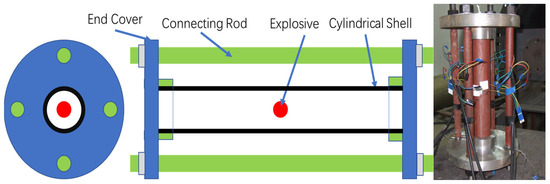
Figure 1.
The cylindrical shell experiment structure.

Table 1.
The arrangement of each experiment.
Two kinds of explosives were used in the experiment. One is a spherical explosive detonated at the center, which had a less than 30 g TNT equivalent and is pressed with micron Penta erythrite Tetranitrate (PETN) powder, as shown in Figure 2a. It is used for initiation by a soft lead skin blasting cable with a diameter of 1 mm and a linear charge density of 0.5 gRXD/m. The white crystal PETN is a simple explosive, with a melting point of 141.3 °C, crystal density of 1.77 g/cm3, explosive velocity of 8300 m/s, and explosive heat of 5895 kJ/kg. In addition, it is not hygroscopic, and is insoluble in water but dissolves easily in acetone. The explosive of more than 30 g TNT equivalent is composed of two main hemispheric explosives and a small explosive ball for detonating in the center, as shown in Figure 2b. The white ball with a diameter of 10 mm is a detonating ball (PETN) with 1 gTNT equivalent, and the main explosive composition of Hexogen/Trinitrotoluene (RDX/TNT:60/40) has an equivalent ratio of 1.25 and a density of 1.65 g/cm3.

Figure 2.
Two kinds of explosives. (a) PETN; (b) RDX/TNT.
A strain gauge was pasted on the outer wall of the cylindrical shell to measure the dynamic strain and to understand the stress and deformation of the container. Parameters of stain gauge are shown in Table 2. From the center of the explosion, four strain measuring points were laid at 0 mm, R, and 2R, respectively, each being divided into two channels of a toroidal and axial signals, forming a total of eight channels of signals and eight test cables. The signal produced and then amplified by the strain gauge was transmitted to the oscilloscope for recording.

Table 2.
Strain gauge.
2.2. Experimental Results
The experimental results are shown in Figure 3 and Figure 4. Figure 3 shows the cylindrical deformation in different scaled distances and thicknesses, while Figure 4 shows the deformation experiment of an 8-mm-thick shell. As can be seen from Figure 3, the maximum deformation presents a drum package near the explosion center under 16 g TNT, with a deformation rate of 5%, without the presence of the rupture of the cylinder shell. The explosion center begins to rupture under 27 g TNT, and the deformation of the shell center is 13%. Penetrable cracks appear at the explosion center under 41.6 g TNT. The maximum deformation is about 3.5% for a 14-mm thickness shell under 80 g TNT, but the shell cracks appear inside the cylindrical shell in the direction of crack propagation. Moreover, the middle section of the 14-mm thickness shell has been broken and disintegrated under 145 g TNT. The maximum deformation of a 20-mm thickness shell is about 2.5% under 233 g TNT, without the presence of the shell rupture. There is an obvious bulge near the explosion center of the 20-mm thickness shell under 403 g TNT without the presence of shell rupture, and the largest deformation is about 3.5% near the middle section. However, the shell is broken and disintegrated with a 20-mm-thick under 623 g TNT, and the shell deformation is estimated to be about 13.5%.
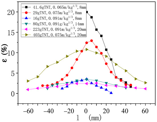
Figure 3.
Deformation in different scaled distances and shell thicknesses.
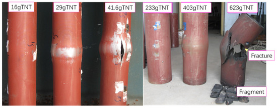
Figure 4.
Shell deformation experiment picture of 0.8 m and 2 cm thickness.
With the increase in the explosive quantity, the cylindrical shell’s longitudinal fracture, a shear oblique section that is basically parallel to the axis becomes more serious, while the crack forms an angle in the radial direction (about 45 °C) instead of extending along the radial direction.
3. Experimental and Numerical Simulation Data Analysis
As the inertia effect of the structure and the strain rate effect should be considered in the deformation process, the stress state and its analysis method of the shell are essentially different between the inside explosion and static load [22,23]. Therefore, the nonlinear dynamic finite element software LS-DYNA was used to not only simulate the elastic-plastic dynamic response of the shell under the explosion, but to analyze the stress state [24,25].
3.1. Finite Element Modeling
The nonlinear dynamic finite element analysis program LS-DYNA was used to analyze the dynamic response of the shell along the thickness and length directions. The calculated explosive density was 1.65 g/cm3, the shape and equivalent of explosion were consistent with that in the actual experiment, and the explosive was detonated at the middle of the cylindrical shell. The Arbitrary Lagrangian Eulado matter algorithm was applied for the explosive and air units in LS-DYNA [26], and the Lagrangian algorithm was used for the cylindrical shell units. The ALE and Lagrange grids overlapped and crossed each other during modeling, and the fluid−structure coupling simulation of the structural mechanical loading by explosive products in the explosion process was realized by the coupling of Lagrange and ALE. According to previous experimental measurements, the detonation velocity of TNT with a density of 1.65 g/cm3 was about 7.8 km/s, while the detonation pressure was 176 GPa [27]. The steel cylinder was made of ideal elastic-plastic material, with a yield strength of 1000 Mpa, while the strain rate and strain strengthening effect were not considered. Figure 5 shows the numerical model diagram for simulating the cylinder deformation under an explosive load.

Figure 5.
Numerical model.
3.2. Material Constitutive Model
The explosive action belongs to the strong impact action, indicating that the metal materials have a strain rate effect under a strong impact load. The material for the numerical model is selected for a constitutive model that can describe the mechanical behavior of metal under a high strain rate, and mainly considers two factors: (1) material strength, that is, the charge of material strength under a large strain rate, and (2) equation of state, that is, the material will have plastic flow due to its large deformation or even failure. Therefore, there must be a state equation describing the fluid mechanical behavior of the material in the constitutive relation.
The strength model adopts the Johnson−Cook model:
where A is the yield stress, B is the strain hardening coefficient, ε is the equivalent plastic strain, n is the strain hardening index, C is the strain rate correlation index, ε* is the reference strain ratio, T is the relative temperature, and m is the temperature softening coefficient, as shown in Table 3. The three parentheses reflect the strain (pressure) effect, the strain rate effect, and the thermodynamic effect, respectively.

Table 3.
Material parameters.
The temperature term of the Johnson−Cook constitutive equation obtained from the macroscopic test can describe the thermal softening property of the material itself, but fails to better reflect the softening property of the material under adiabatic shear that is described by introducing the failure model of plastic shear softening.
where D is the adiabatic shear, εcr is the initial strain for the occurrence of adiabatic shear damage, and εf is the failure strain when the material produces adiabatic shear. Once damage occurs inside the material, the flow stress in the damage zone is as follows:
where σ is the flow stress, σ0 is the initial flow stress, and D is the adiabatic shear. This state equation is similar to the Gruneisen state equation in LS-DYNA. The failure criterion is based on the ideal material, which is not limited by defects and other factors. In this study, a single failure threshold (strain 0.25) was selected as the failure criterion.
3.3. Numerical Simulation Results
Figure 6, Figure 7 and Figure 8 show the circumferential strain cloud diagrams of 8 mm, 14 mm, and 20 mm-thick cylindrical shells under different charges by numerical simulation, while the numerical calculation results were compared with the experimental results, as shown in Figure 9.

Figure 6.
Circumferential strain cloud of 8 mm-thick shell at 16, 29 and 41.6 g TNT.

Figure 7.
Circumferential strain cloud of 14 mm-thick shell at 80, 145, and 233 g TNT.

Figure 8.
Circumferential strain cloud of 20 mm-thick shell at 233, 403, and 623 g TNT.
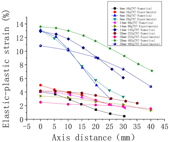
Figure 9.
Comparison between experimental and numerical results.
The numerical results show that the deformation of cylindrical shells with different thicknesses at the blast center is basically identical at the same specific distance. The experimental results show that under the same specific distance, the deformation at the explosion center of 20-mm-thick cylindrical shell is smaller than that at the explosion of the 8-mm-thick cylindrical shell. The experimental results are inconsistent with those by numerical simulation, mainly because the influence of the stress gradient along the thickness direction of the shell and different fracture modes on the overall strength of the material was not considered in the numerical simulation. This problem can be solved by accumulating experimental data and constantly modifying the parameters of the numerical simulation.
The calculation results of the dynamic response of the cylindrical shell under loading of 41.6 g TNT explosive shock wave are analyzed as an example. Figure 10 shows the pressure time−history curve of the explosive shock wave loaded onto the inner surface of the cylindrical shell directly opposite to the explosion core. It can be seen from the curve that the explosive shock wave formed by the TNT explosion is loaded onto the inner surface of the cylindrical shell after propagating for a period of time (about 11 μs in front of the pressure curve of the shock wave loaded on the inner surface of the cylindrical shell). The shock wave pressure rises rapidly on the inner surface of the shell, and the peak pressure on the blast core reaches 1000 MPa. Under the action of high intensity shock wave pressure, the shell rapidly deforms in the radial direction. According to the principle of explosion mechanics, the load intensity of the blast wave decreases with the increase of the distance from the explosion center. Therefore, the point on the inner surface of the cylindrical shell with a larger distance from the explosion center section will bear a smaller load of the blast wave, resulting in overall deformation of the cylindrical shell that is radially bulging.
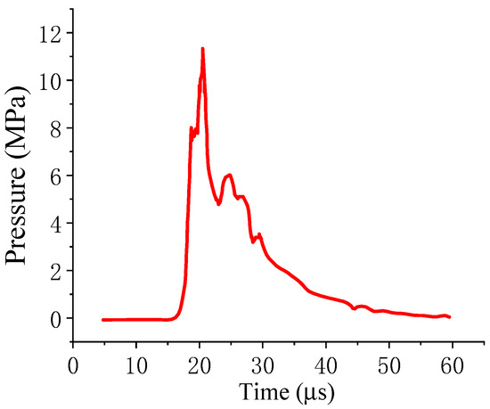
Figure 10.
Pressure and time curve of the blast wave.
The explosive loading of the destruction process of 20# steel-made cylindrical shell is shown in Figure 11. It can be seen that along with the column shell expansion process, the plastic damage zone is first formed within the shell, and then the crack produced by the shell wall of the damage area extends outward along the direction of the shear surface, and finally forms the internal initial shear failure along the shear direction.
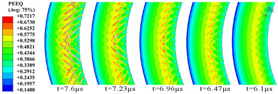
Figure 11.
Time−history diagram of shell failure under 41.6 g TNT.
Table 4 shows the numerical simulation results. It can be seen that the deformation of the middle section at the same specific distance has little difference under different thicknesses of shells, while the deformation decreases more slowly as the thickness increases at the far end of the core section.

Table 4.
The numerical simulation of 20# steel.
The numerical simulation results of the 8-mm-thick steel shell of under 16 g TNT are analyzed. The steel shell is divided into three thickness units along the radial direction (Units 1, 2, and 3), with positions of 0 mm, 4 mm, and 8 mm. Unit 1 is the inside surface of shell, Unit 2 the middle section, and Unit 3 the outer side of the shell. It obtains the time history law of the radial stress, hoop stress, and axial stress of three points. Figure 12 shows the time history curves of radial stress of three point and experimental fracture. The shell is in the state of compressive stress in radial, hoop, and axial directions at the initial stage of the explosion shock wave loading and unloading (about the time period of 12–25 μs), but the compressive stress and response time decrease gradually in the radial, hoop, and axial directions from the inside to the outer surface. The Unit 3 point of the shell changed to a tensile stress state after a short-time hoop compressive stress. There are two reasons for this: One is the high strength and short time of the radial loading of the shell by the blast shock wave, which causes an extremely high hydrostatic stress for a short period of time (2–3 μs). The other is the high speed of the radial propagation of the stress wave in the shell, which results in the time of less than 2 μs for the stress wave passing through the whole shell, as well as a period of about 90 μs for the radial expansion vibration of the shell. Therefore, the one-quarter period of the structure response is much larger than the time of the stress wave passing through the whole shell wall. In the initial stage of radial deformation (about 15–25 μs for the blast loading), the radial, hoop, and axial stresses are compressive stress in a certain range near the inside surface, while the shell is in the tensile stress state in a certain range near the outer surface. With the increase of the radial deformation of the shell, the pressure of the explosion shock wave is gradually unloaded, the stress wave inside the shell is gradually reduced, and the axial and hoop stress state of the shell is gradually changed from the compressive stress state to the tensile stress state within a certain range of the inner surface. However, the tensile stress on the outer surface of the shell is greater than that on the inner surface for a considerable period of time (about 100 μs). The results show that the internal stress state of the shell is controlled by the high-intensity explosive shock wave load and the radial deformation of the shell. This is a remarkable difference from the normal axisymmetric static stress state. In addition, the axial tensile stress is smaller than the hoop tensile stress in the local radial deformation process of the shell.
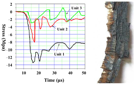
Figure 12.
The time−history curves of radial stress of three point and experimental fracture4. Dynamic Fracture Analysis of Cylindrical Shells.
Figure 13 shows the metallography of 20# shell before experiment. Figure 14 shows the cross-section diagram of recovered fragments of the shell during the solid filling loading of RDX/TNT. It can be seen that adiabatic shear bands, starting from the inner wall area, are distributed along the radial direction of 45° or 135° on the inner surface of the shell, and have different degrees of development; some only appear on the inner surface, and a few well-developed ones have basically extended to the outer surface and lead to steps on the outer surface of the shell, as shown in Figure 14a. The cracks start from the inner wall and develop along the adiabatic shear band to the outer surface. Figure 14b,c shows the characteristics of shear bands in local areas. The adiabatic shear bands are in cross distribution on the inner wall, and the interval between their starting points is about 320~450 μm.
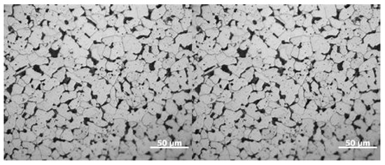
Figure 13.
Metallography of 20# shell before the experiment.
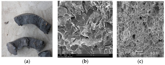
Figure 14.
Shear characters and metallography of fragment surface. (a) Fragment of section; (b) Metallographic 1; (c) Metallographic 2.
4. Conclusions
The research mainly comes from the military field on the deformation, damage, and failure modes of cylindrical shell structures under explosive loading. It is a complex process that expansion of shell under explosive load which involves material failure under a strong impact load and structural failure under high strain rate loading. This problem is of great significance in structural protection and weapon design. Therefore, the problem has always been the focus of research, namely the expansion and fracture of cylindrical shells under an explosive load. There are various factors related to the failure process and fracture mode of the metal cylindrical shell under the detonation load. A thorough understanding of the physical mechanism of the expansion fracture of metallic cylindrical shells under explosion loading can provide a basis for military and industrial design and manufacturing.
Based on the plasticity theory, the paper discusses the evolution characteristics of stress state during the expansion process of cylindrical shells under different explosion pressures, and provides an analysis of the explosion pressure effect on the tensile fracture and shear fracture. Experiments were carried out to investigate the effects of load pulse width and explosive pressures on the fracture characteristics of the shell. Through the macroscopic and microscopic analysis of the recovered fragments, the effects of different load characteristics on the expansion deformation, failure process, and fracture mode of the 20# shell structure were discussed. The results show the following:
- (1)
- The results from the plasticity theory show that when the detonation pressure is small, the closer the zero hydrostatic interface to the inner wall, the larger the tensile fracture zone. As the explosion pressure increases, the hydrostatic stress zone increases, indicating that the thermoplastic instability of the material is more likely to occur near the inner surface, resulting in a shear weak zone and adiabatic shear failure starting near the inner wall.
- (2)
- The adiabatic shear band was only found in front of the crack starting from the inner wall, rather than in the inner wall area. With the increase of the load peak value, cross or parallel adiabatic shear bands appear in the inner wall of the shell, and their spacing decreases with the increase of the load peak value. When the load peak is further increased, the shell locally presents a single-spin failure mode, and there are a large number of adiabatic shear bands parallel to the fault plane along the direction of the shell wall thickness.
Author Contributions
Conceptualization, D.W.; methodology, X.Q. and W.C.; validation, D.W.; formal analysis, D.W. and W.C.; investigation, D.W.; data curation, D.W.; writing—original draft preparation, D.W.; writing—review and editing, D.W., X.Q. and S.W.; supervision, S.W.; funding acquisition, S.W. All authors have read and agreed to the published version of the manuscript.
Funding
This work was supported by the key project of Intergovernmental International Scientific and Technological Innovation Cooperation in China under Grant No.2016YFE0128900, and the National Natural Science Foundation of China under Grant No.11775166.
Institutional Review Board Statement
Not applicable.
Informed Consent Statement
Not applicable.
Data Availability Statement
All data included in this study are available upon request by contact with the corresponding author.
Conflicts of Interest
The authors declare no conflict of interest.
References
- Arnold, W.; Rottenkolber, E. Fragment mass distribution of metal cased explosive charges. Int. J. Impacting Eng. 2008, 35, 1393–1398. [Google Scholar] [CrossRef] [Green Version]
- Shen, Z.X.; Li, Y.Z.; Zhang, H.L. Experimental studies on failure mode of low-speed projectiles by local modification on steel plates. Chin. J. High Pressure Phys. 2017, 31, 202–207. [Google Scholar]
- Wang, Z.R.; Jiang, J.C.; Xu, J. Dynamic response of pressure-shock-resistant vessel subjected to gas explosion load. J. Petrochem. Univ. 2006, 19, 76–80. [Google Scholar]
- Xin, J.; Ma, L.; Hu, Y. Fracture analysis of stainless-steel tube under internal blasting loading. Pressure Vessel Technol. 2013, 30, 66–72. [Google Scholar]
- Lu, S.Z.; Wang, W.; Zhang, B.Y. Experimental research on destruction mechanism of large-scale floating-roof oil tank under blast loading. Explosive. Shock. Waves 2011, 31, 158–164. [Google Scholar]
- Chen, F.Z.; Zhang, M.G.; Wang, Y. Risk analysis of coupling domino effect in petroliferous tank farm. J. China Saf. Sci. 2017, 10, 111–116. [Google Scholar]
- Gurnery, R.W. The initial velocities of fragments from bombs, shells and grenades: BRL 405. In Initial Velocities of Fragments from Bombs Shell Grenades, Lawrence Livermore National Laboratory; Defense Technical Information Center: Fort Belvoir, VA, USA, 1943. [Google Scholar]
- Taylor, G.I. Analysis of the Explosion of a Long Cylindrical Bomb Detonated at One End; The National Archives: Richmond, UK, 1941.
- Hoggatt, R.H.; Recht, R.F. Fracture behavior of tubular bombs. J. Appl. Phys. 1968, 39, 1856–1862. [Google Scholar] [CrossRef]
- Mott, N.F. Fragmentation of shell cases. Math. Phys. Sci. 1947, 189, 300–308. [Google Scholar]
- Grady, D.E. Fragmentation of Rings and Shells; Springer: New York, NY, USA, 2006. [Google Scholar]
- Hiroe, T.; Fujiwara, K.; Hata, H. Deformation and fragmentation behavior of exploded metal cylinders and the effects of wall materials, configuration, explosive energy and initiated locations. Int. J. Impacting Eng. 2008, 35, 1578–1586. [Google Scholar] [CrossRef] [Green Version]
- Tanapornraweekit, G.; Kulsirikasem, W. FEM simulation of HE blast-fragmentation warhead and the calculation of lethal range. World Acad. Sci. Eng. Technol. 2012, 6, 411–415. [Google Scholar]
- Olive, F.; Nicaud, A.; Marilleau, J. Rupture behavior of metals in explosive expansion. Inst. Phys. Conf. Ser. 1979, 47, 242–252. [Google Scholar]
- Kong, X.S.; Wu, W.G.; Li, J. A numerical investigation on explosive fragmentation of metal casing using smoothed particle hydrodynamic method. Mater. Des. 2013, 51, 729–741. [Google Scholar] [CrossRef]
- Shen, Z.X.; Yuan, S.Q.; Chen, J. Fragmentation of metal cylindrical shell treated by local quenching. Chin. J. High Pressure Phys. 2015, 29, 293–298. [Google Scholar]
- Razzakov, S.R.; Matniyazov, B.I.; Berdiev, O.B. Calculation of the Bearing Capacity of Conical Shells with Cyclic Symmetry under Long-Term Loading, Risk Assessment and Safety in Construction; MGSU: Moscow, Russia, 2012; pp. 159–168. [Google Scholar]
- Razakov, S.R.; Friedman, G.S.; Razzakov, N.S. Evolution of dynamic parameters the composite spatial constructions in the process operation. In Collection of Reports of an International Scientific and Practical Conference; MISI-MGSU: Moscow, Russia, 2018; pp. 356–361. [Google Scholar]
- Razzakov, K.S. Load-carrying capacity of reinforced concrete plates of shells on the flat contour. In Proceedings of the I International Azerbayjan-Ukraina «Building Innovations-2018», Baku, Ukraine, 20 May 2018; pp. 189–191. [Google Scholar]
- Razzakov, S.R. Seismic Resistance of Nonlinearly Deformable Large-Span Spatial Structures, taking into Account Changing Dynamic Stiffness. Key Eng. Mater. 2021, 887, 672–679. [Google Scholar] [CrossRef]
- Gao, F.Y.; Long, Y.; Ji, C.; Zhang, C.X. Research on Dynamic Response of Q235 Steel Cylindrical Shell Subjected to Lateral Explosion Loading. Adv. Mater. Res. 2013, 631–632, 864–869. [Google Scholar] [CrossRef]
- Lei, J.H.; Liu, X.S.; Wang, Q.; Zhang, M.E. Study on machining deformation control of fiber-metal laminates. J. Polym. Compos. 2020, 41, 2866–2874. [Google Scholar] [CrossRef]
- Wang, L.; Hao, S. Machining deformation prediction of thin-walled workpieces in five-axis flank milling. J. Int. J. Adv. Manuf. Technol. 2018, 97, 4179–4193. [Google Scholar] [CrossRef]
- Hao, X.Z.; Li, Y.G.; Zhao, Z.W.; Liu, C.Q. Dynamic machining process planning incorporating in-process workpiece deformation data for large-size aircraft structural parts. J. Int. J. Comput. Integr. Manuf. 2019, 32, 136–147. [Google Scholar] [CrossRef]
- Fu, S.L.; Feng, P.F.; Ma, Y.; Wang, L.P. Initial residual stress measurement based on piecewise calculation methods for predicting machining deformation of aeronautical monolithic components. J. Int. J. Adv. Manuf. Technol. 2020, 108, 2063–2078. [Google Scholar] [CrossRef]
- Deng, J.; Zhou, S.J.; Gao, H.J.; Lin, M.H.; Li, X. Numerical Simulation Investigation on Machining Deformation of Aviation Thin-Walled Parts Caused by Residual Stress. Mater. Sci. Forum 2021, 1032, 186–191. [Google Scholar] [CrossRef]
- Li, X.Y.; Li, L.; Yang, Y.F.; Zhao, G.L.; He, N.; Ding, X.C.; Shi, Y.W.; Fan, L.X.; Lan, H.; Jamil, M. Machining Deformation of Single-Sided Component Based on Finishing Allowance Optimization. Chin. J. Aeronaut. 2019, 33, 2434–2444. [Google Scholar] [CrossRef]
Publisher’s Note: MDPI stays neutral with regard to jurisdictional claims in published maps and institutional affiliations. |
© 2022 by the authors. Licensee MDPI, Basel, Switzerland. This article is an open access article distributed under the terms and conditions of the Creative Commons Attribution (CC BY) license (https://creativecommons.org/licenses/by/4.0/).