Article

Theoretical and Experimental Investigation on SiC/SiC Ceramic Matrix Composites Machining with Laser Water Jet

1
School of Mechatronics Engineering, Harbin Institute of Technology, Harbin 150001, China
2
Key Laboratory of Micro-Systems and Micro-Structures Manufacturing, Ministry of Education, Harbin Institute of Technology, Harbin 150001, China
*
Authors to whom correspondence should be addressed.
Appl. Sci. 2022, 12(3), 1214; https://doi.org/10.3390/app12031214
Submission received: 17 December 2021 / Revised: 15 January 2022 / Accepted: 21 January 2022 / Published: 24 January 2022
(This article belongs to the Special Issue Laser Micro/Nano Machining Technology)

Abstract

:
SiC/SiC ceramic matrix composites (CMCs) are widely applied in the aerospace and nuclear industries due to their excellent material nature (strength, hardness, and irradiation tolerance) at high-temperature loads. However, high-quality machining cannot be easily realized because of the anisotropic material structure and its properties. In this study, a laser water jet (LWJ) was adopted for CMCs machining. Firstly, the finite element model (FEM) was established describing a representative three-dimensional microstructure including weft yarn, warp yarn, SiC base, and the pyrolytic carbon (PyC) fiber coating. The temperature distribution, as well as its evolution rule on substrate surface under LWJ machining, was analyzed. Moreover, a single-dot ablation test was carried out to verify the accuracy of the numerical simulation model. Secondly, the variation in maximum temperatures under different laser pulse energy was obtained by means of FEM. Nonetheless, a non-negligible deviation emerged in the ablation depth of the numerical calculation and experimental results. Although the simulation results were obviously superior to the experimental results, their proportions of different machining parameters reached an agreement. This phenomenon can be explained by the processing characteristics of LWJ. Finally, single-row and multi-row scribing experiments for CMCs with 3 mm thickness were developed to clarify the processing capacity of LWJ. The experimental results indicated that single-tow scribing has a limiting value at a groove depth of 2461 μm, while complete cutting off can only be realized by multi-row scribing of LWJ. In addition, the cross-section of CMCs treated by LWJ presented a surface morphology without a recast layer, pulling out of SiC fibers, and delamination. The theoretical and experimental results can offer primary technical support for the high-quality machining of CMCs.

1. Introduction

As a type of emerging composite, SiC CMCs have been widely employed in the aerospace and nuclear industries owing to their unique material parameters including a better strength to weight ratio, high toughness, superior resistance to heat effects, and low density [1,2,3]. For example, CMCs are composed of braided SiC fibers whose hardness is 9.5 on the Mohs scale. Furthermore, the CMCs could maintain their high strength property even under a high-temperature load of 1500 K, which is 150 K higher than Nickel-based superalloys [4]. It is worth noting that the density of CMCs material is only 30% of superalloys, which is beneficial for its application in the aerospace field [5]. Due to their excellent material performance, researchers have shown an increased interest in application studies of CMCs. However, a series of challenges have been raised by the outstanding material properties for CMCs machining.
Due to the anisotropic woven SiC fibers, ultrahigh hardness, and strength, it is difficult to obtain a promising result for conventional machining techniques. Various manufacturing deficiencies exist, such as pulling out of SiC fibers, delamination, and burrs in the processing area [6]. Differing from conventional machining, special processing techniques were introduced into CMCs machining with non-contact including laser processing, water jet machining, electric discharge processing, and LWJ [7]. The heat-affected zone (HAZ) and recast layer in the machining area can hardly be avoided during laser and electric discharge processing [8,9]. The pullout of SiC fibers is always accompanied by water jet machining on account of super high water pressure (100–400 Mpa) [10]. Among these techniques, the LWJ may achieve a satisfactory processing result for CMCs with high precision due to its unique properties. This technology was first introduced in the material processing field in 1996 by Dr. Richerzhagen, with the successful coupling of the water jet and focused laser spot [11]. LWJ could be considered as a kind of “cold machining” technique owing to the forced cooling and scouring effect of the water jet, so that characteristics such as low taper, high depth-to-width/ diameter ratio, less/no HAZ, and recast layer could be easily acquired [12,13]. In particular, there is a great advantage for LWJ compared to a conventional laser in that focusing the laser spot on the material in processing is no longer necessary. Moreover, all the compact sections of the water jet play a role as machine tools that could reach a maximum length of 100 mm [14].
According to the literature results up to now, there has been no detailed investigation on removal mechanism as well as high-quality processing of CMCs under LWJ machining in any systematic way. In this study, the three-dimensional FEM describing a representative microstructure of CMCs was established to explore the ablation mechanism during LWJ machining. The temperature distribution and its evolution rule on a temporal and spatial scale were analyzed through a numerical simulation. Then, the effect of cooling and scouring brought about by a water jet was validated by a series of relevant experiments. The influences of different laser pulse energies on the ablation depth were also revealed with the interpretation of FEM. Single-row scribing experiments were put forward to discover the limit value of groove depth. On this basis, a multi-row scribing experiment was established to realize the thorough cutting of the CMCs substrate with the absence of a recast layer, pulling out of SiC fibers, and delamination. In addition, the mechanism of CMCs machining with LWJ was summarized according to theoretical and experimental research.

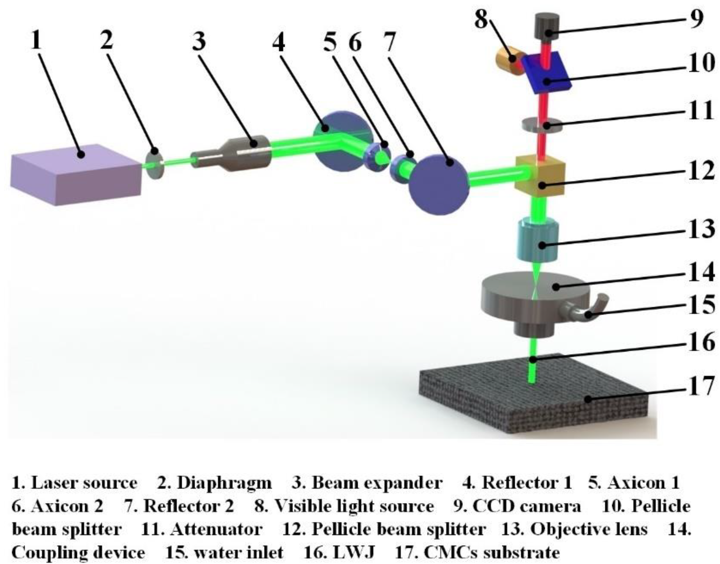
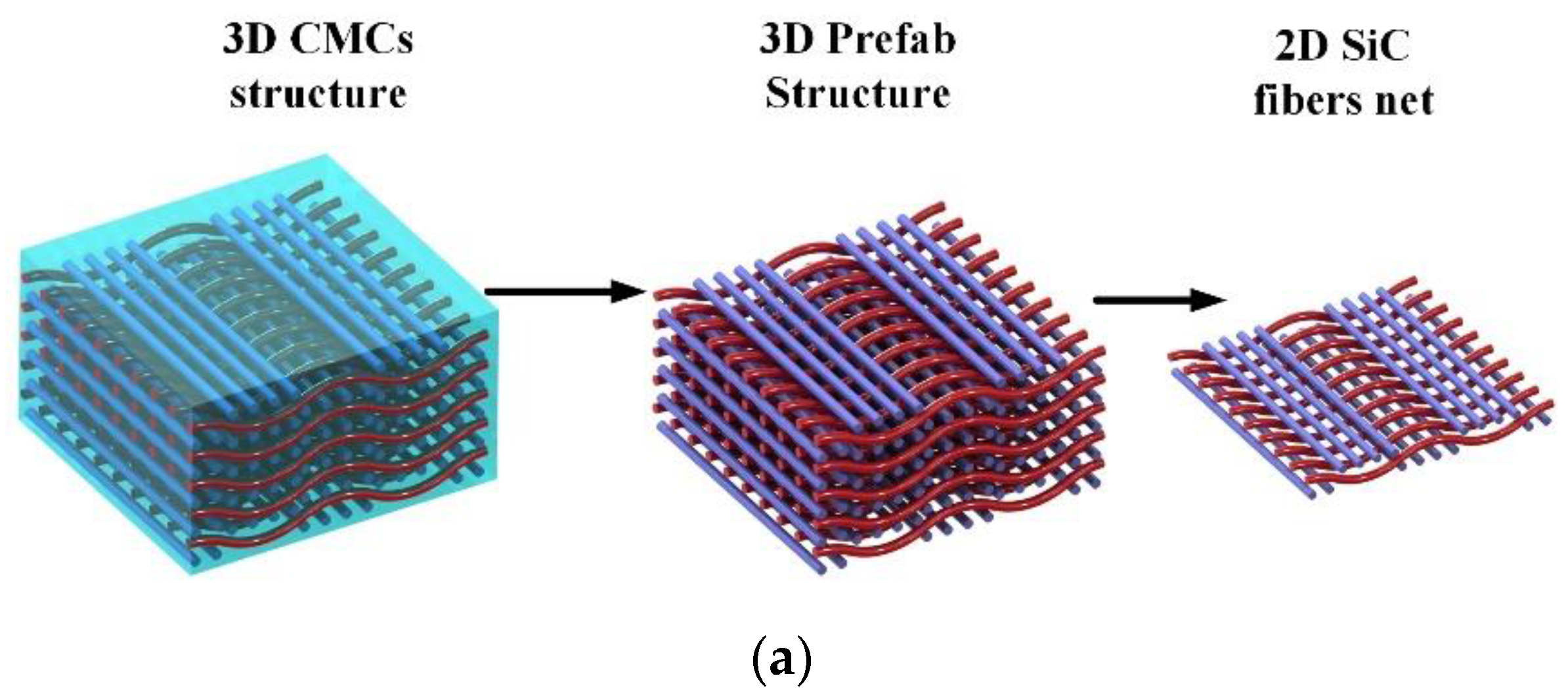
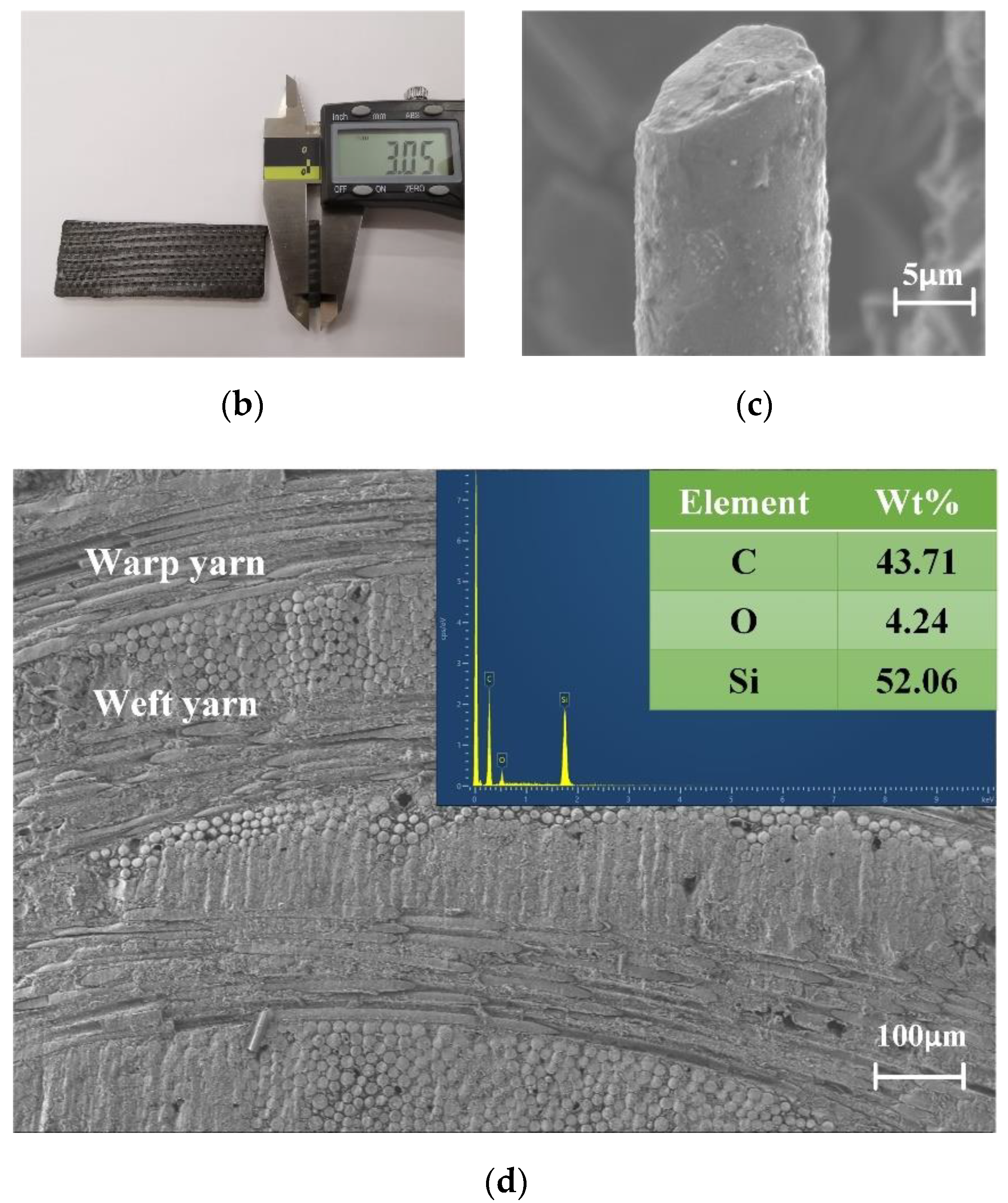
2. Experimental Setup and Material

In this paper, a nanosecond laser source (Pulse 532-50-LP) was selected for LWJ machining according to the research findings of Hale and Querry [15]. The main parameters are shown in Table 1. The schematic diagram of the LWJ machining system is demonstrated in Figure 1 which is similar to that employed by Cheng et al. [16]. By means of beam expansion, reflection, and spatial shaping, the laser beam is finally focused onto the upper surface of the ruby nozzle. With the assistance of the coaxial observing system, the focused laser spot is delivered into the nozzle with a diameter of 60 μm. Hence, a coupling jet is generated which can be utilized for CMCs machining. For the purpose of increasing the coupling efficiency, i.e., reducing the loss of laser energy in the machining process, ultrapure water was employed in the hydraulic system.
The CMCs substrates applied in this study were supplied by AVIC Manufacturing Technology Institute. The detailed parameters are listed in Table 2. As shown in Figure 2 a–d, the anisotropic woven SiC fibers are demonstrated as a schematic diagram of three-dimensional CMCs and their actual morphology. The average diameter of the fiber is approximately 11 μm with a 1μm PyC coating which is similar to that employed by Cheng et al. [16].

3. Modeling Approaches

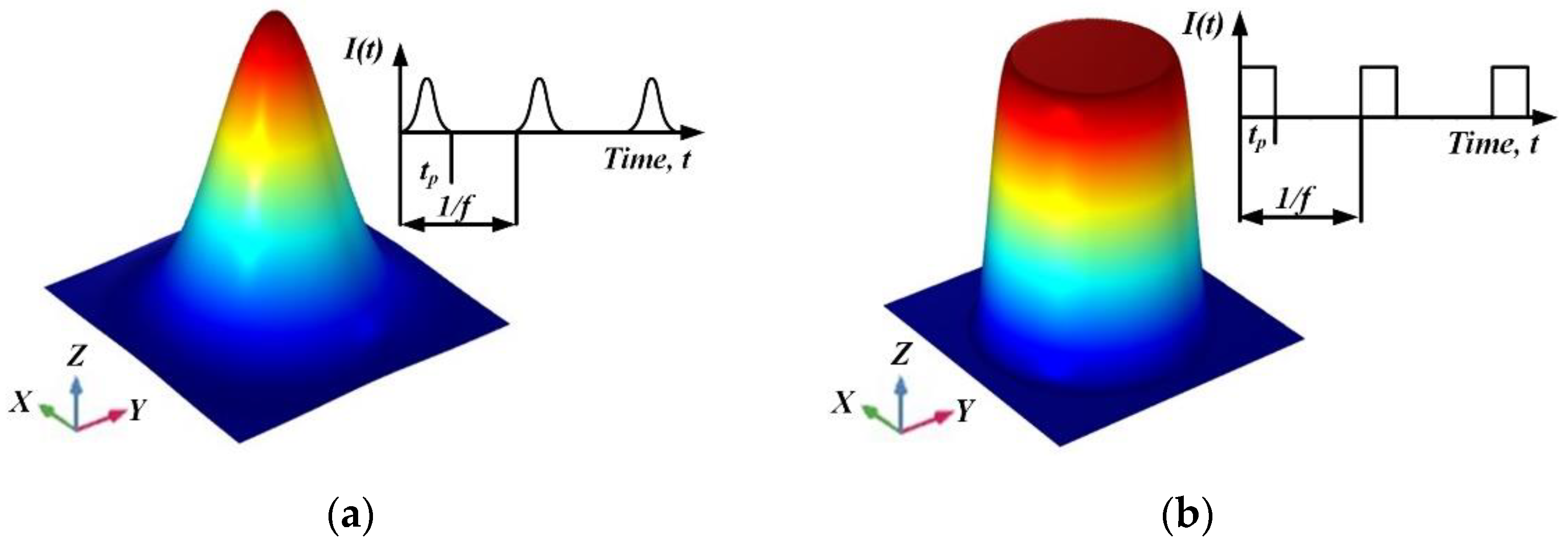
3.1. Theoretical Background of LWJ Machining

According to the first law of thermodynamics, the governing equation of transient heat transfer which describes the process of time-dependent heat conduction in the material domain subject [17], can be written as Equation (1):
ρ c p T t = · [ k ( T ) T ] + A + A L
where ρ is the density of CMCs, cp is the specific heat capacity of CMCs, t is the time, k is the thermal conductivity of CMCs, A is the laser heat source term, and AL is melting latent heat. For a three-dimension Cartesian coordinate system, Equation (1) can be rewritten as follows:
ρ c p T t = x [ k x ( T ) T x ] + y [ k y ( T ) T y ] + z [ k z ( T ) T z ] + A + A L
The interaction between LWJ and substrate is a complex issue that involves optics, heat transfer theory, and fluid mechanics. To solve the transient heat transfer equation of LWJ machining CMCs, several assumptions are raised to simplify the physical model properly in this paper.
  • According to the total reflection at the air–water interface, the energy distribution of LWJ is uniform on the cross-section of the water jet [18,19]. A flat distribution of laser intensity at the workpiece is assumed instead of a Gaussian distribution, which is shown in Figure 3.
  • The maximum temperature on the substrate surface during the numerical simulation is the melting point of CMCs. When the temperature of one element reaches the melting point, it is assumed to be ablated from the substrate.
  • Heat conduction and heat convection are considered during LWJ machining. Moreover, heat convection is limited in the stagnation cooling area in this study in view of the selection of the Nusselt number.
  • Considering the significantly forced cooling and scouring effect, the flow field in the molten pool is ignored.
According to the assumptions above, the laser energy distribution of LWJ on the substrate can be regarded as a multi-mode fiber laser [20]. Therefore, the heat flux of LWJ can be described as Equation (3):
I ( t ) = P ( t ) / ( π d 2 / 4 )
where I is the time-dependent function of the laser incident energy, P is the laser output power on the surface of CMCs substrate, and d is the diameter of the water jet.
According to physical assumption (1), Equation (3) can be further simplified to a surface heat flux instead of a volume heat source, as represented as Equation (4):
q z = 0 = I ( t ) [ n e z ]
where n is a unit vector normal to the material surface, ez is a unit vector parallel to the z axis.
On the basis of physical assumption 3, the forced heat convection of the water jet should be considered and calculated. Unlike the loading of the laser heat flux, the forced heat convection of the water jet occurs throughout the LWJ machining on the contact area between the water jet and substrate. The coefficient of convective heat transfer can be expressed as follows:
h f w = N u k w / l
where Nu is the Nusselt number, kw is the thermal conductivity of water, and l is the feature size.
In particular, the Nusselt number indicates a close relationship with the status of the affected zone of LWJ, with a proportion quite to the stagnation cooling area referred to in physical assumption (3). According to Webb and Ma [21], an empirical formula of N u is obtained as Equation (6):
N u = { 0.715 R e 1 / 2 P r 0.4 0.797 R e 1 / 2 P r 1 / 3 0.15   <   P r   <   3 P r   >   3
where Re is the Rayleigh number with an expression of R e = ρ w v w l / μ w , ρw is the density of water, vw is the velocity of the water jet, μw is the dynamic viscosity of water. Pr is the Prandtl number with an expression of P r = c p w μ w / k w , cpw is the specific heat capacity of water.
Furthermore, the main factor of CMCs material removal is the instantaneous high temperature caused by LWJ, the model of its heat flux can be written as a slope function:
q a = h a ( T T a )
where ha is the slope, Ta is the ablation temperature of CMCs substrate.
With a view to laser ablation, the normal velocity of grid displacement can be defined as Equation (8):
v a = q a ρ H s
where Hs is the heat of sublimation.

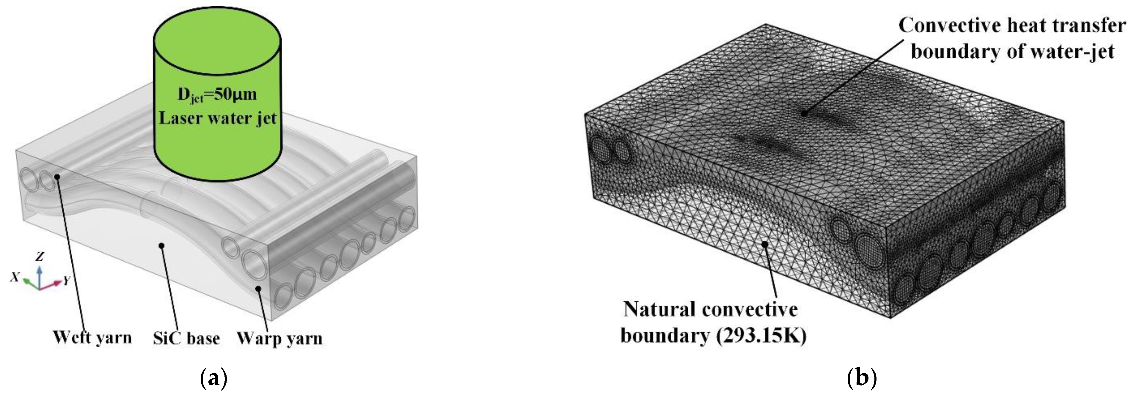
3.2. Geometry and Meshes

According to the actual structure of CMCs in Figure 2, a representative three-dimensional model is established with COMSOL Multiphysics. Figure 4 demonstrates positive isometric drawing and mesh generation of the CMCs model, respectively. In order to guarantee, as much as possible, a precision calculation, a model size of 150 μm (length) × 100 μm (width) × 40μm (height) is adopted. As shown in Figure 4a, curving SiC warp yarn and horizontal SiC weft yarn with 1 μm PyC coating are woven orthogonally. The randomly distributed SiC fibers with 8–15 μm diameters are inlaid into the SiC base. Furthermore, the incidence direction of LWJ is arranged right above the CMCs substrate with a jet diameter of 50 μm due to the contraction effect [22]. Figure 4b exhibits the mesh generation of the CMCs model with a total grid number of 640,000. The free tetrahedral grid method is utilized for the SiC base with a maximum mesh size of 5 μm. The SiC fibers and PyC coating have a relatively small dimension, and the local grid refinement and swept mesh method are adopted with a maximum mesh size of 0.5 μm.

4. Results and Discussions

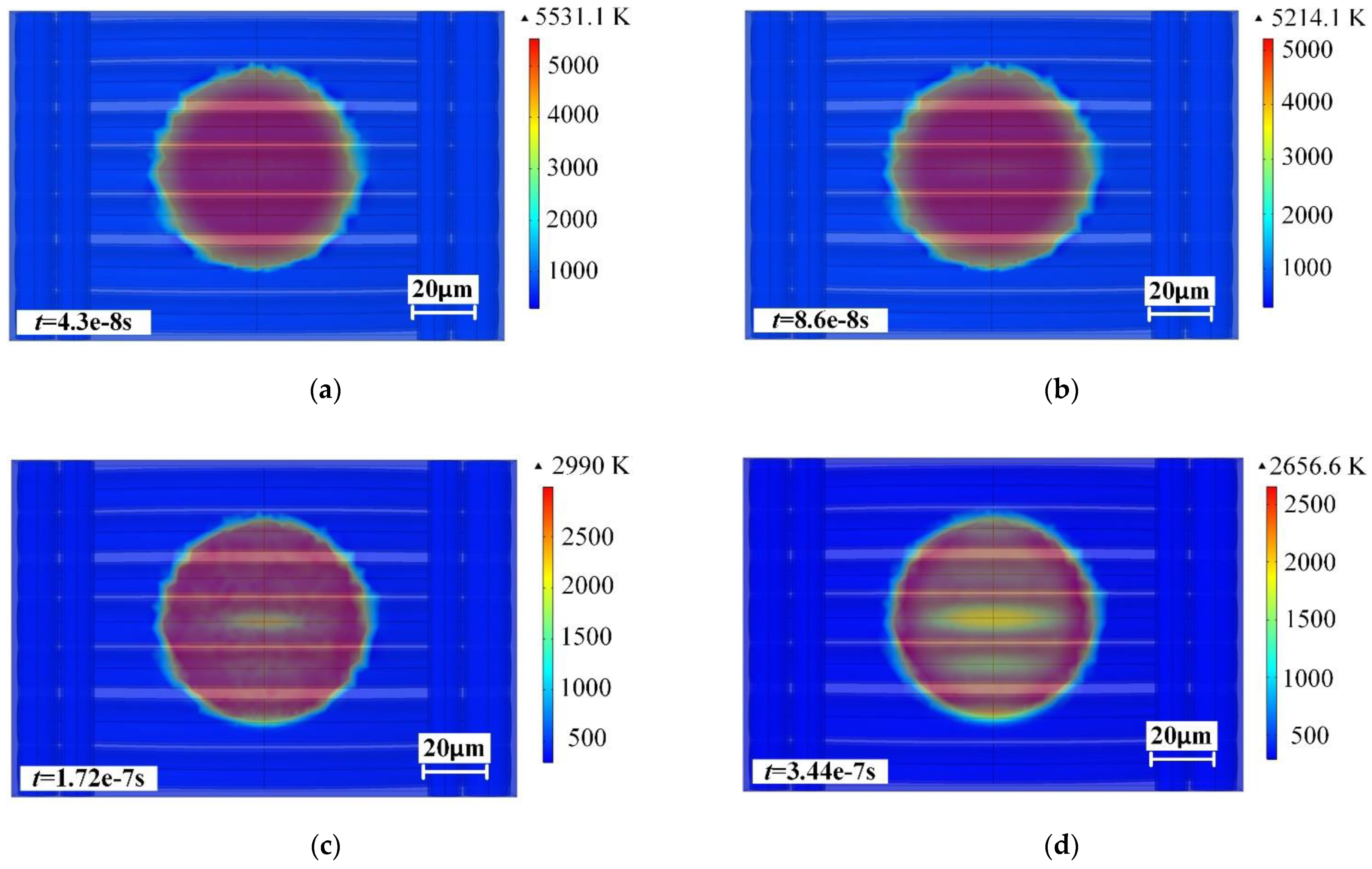
4.1. Spatial and Temporal Distribution of Temperature during LWJ Machining

On the basis of Section 3, in this study, the temperature distribution of CMCs under LWJ was investigated. The numerical simulation was carried out with a configuration of 1 mJ laser pulse energy, 86 ns pulse duration, 20 Mpa water pressure, 60 μm nozzle diameter (50 μm jet diameter), and 293.15 K initial temperature. To conveniently measure the temperature field on the CMCs surface, a series of characteristic time nodes were adopted to describe the evolution of the transient temperature of CMCs in one 1/f period, as shown in Figure 5. With the incidence of the laser pulse, a steep temperature increasing to 5531.1 K could be realized in 4.3 × 10⁻⁸ s (t = tp/2), then the temperature declined gradually to 5214.1 K in 8.6 × 10⁻⁸ s (t = tp), as shown in Figure 5a,b. Then, the laser pulse ends and is followed by the complete cooling stage. Without the input of laser heat flux, the maximum temperature drops rapidly to 2990 K (approximate melting point) in 1.72 × 10⁻⁷ s (t = 2 × tp) and 2656.6 K in 3.44 × 10⁻⁷ s (t = 4 × tp), as demonstrated in Figure 5c,d. These results indicate that CMCs removal only takes place during the laser pulse duration and also the following one. Interestingly, a faster temperature drop appears along the direction of the SiC fiber, which states an anisotropic thermodynamic property of CMCs [23]. As expected, there is an increasing trend of this kind of property in Figure 5e,f. Moreover, annular distributions of temperature are formed gradually. In addition, the maximum temperature in t = 5.16 × 10⁻⁷ s (t = 6 × tp) and t = 8.6 × 10⁻⁷ s (t = 10 × tp) is reduced to 2423.3 K and 2152 K, respectively. According to the definition of the thermal damage threshold (T = 1873.15 K) studied by Jie Chen [24], the temperature distribution in 1.38 × 10⁻⁶ s (t = 16 × tp) was analyzed. As shown in Figure 5g, a low temperature is concentrated in the central zone with a diameter of 50 μm which corresponds to the working area of the water jet. The maximum temperature of 1855 K is distributed around the outer annulus with a unilateral width of 5–7 μm. However, the instantaneous high temperature cannot be maintained under a forced cooling effect of the water jet; therefore, the HAZ can hardly be generated. Finally, the temperature distribution of the last time step of one 1/f period is exhibited in Figure 5h, which is still an annular distribution with a maximum temperature of 494.5 K. It is worth noting that the size of the temperature variation area has not changed in one 1/f period of LWJ. This phenomenon indicates that LWJ could restrain the thermal damage of laser effectively; then, the temperature field is restricted in a fixed size range with the assistance of the forced cooling effect of the water jet.
To verify the thermal effect of LWJ machining, a single-dot ablation test was put forward. The configuration of the experimental parameter was the same as the numerical simulation. Moreover, the machining time was set as 1 s. The experimental result is demonstrated in Figure 6. The hole diameter is approximately 62 μm, which is highly consistent with the numerical result in Figure 5. Moreover, this micro-hole feature is characterized by a clean edge without a recast layer and slag accumulation. The SiC fibers and their coatings can be distinctly observed. This morphology indicates that processing without thermal damage can be obtained with LWJ. It is worth noting that a few fracture phenomena were shown on the entrance of the micro-hole. This result may be explained by the fact that the mechanical property of SiC fibers has been changed due to laser processing. The analysis suggests that the temperature of the SiC fibers around the hole edge can be increased during LWJ machining. Such a temperature rise cannot reach the melting point of CMCs, but it can change the mechanical property of the material to a certain extent. Under the combined effect of the laser pulse energy and water jet, a fracturing of SiC fibers is more likely to occur. Homoplastically, deformation and rupture behaviors were generated by the local and continuous high temperature on the top surface of CMCs, according to the observation of X Jing et al. [25]. In addition, the SiC base and fibers were both removed by LWJ, without defects such as the absence of a base and the pulling out of fibers.

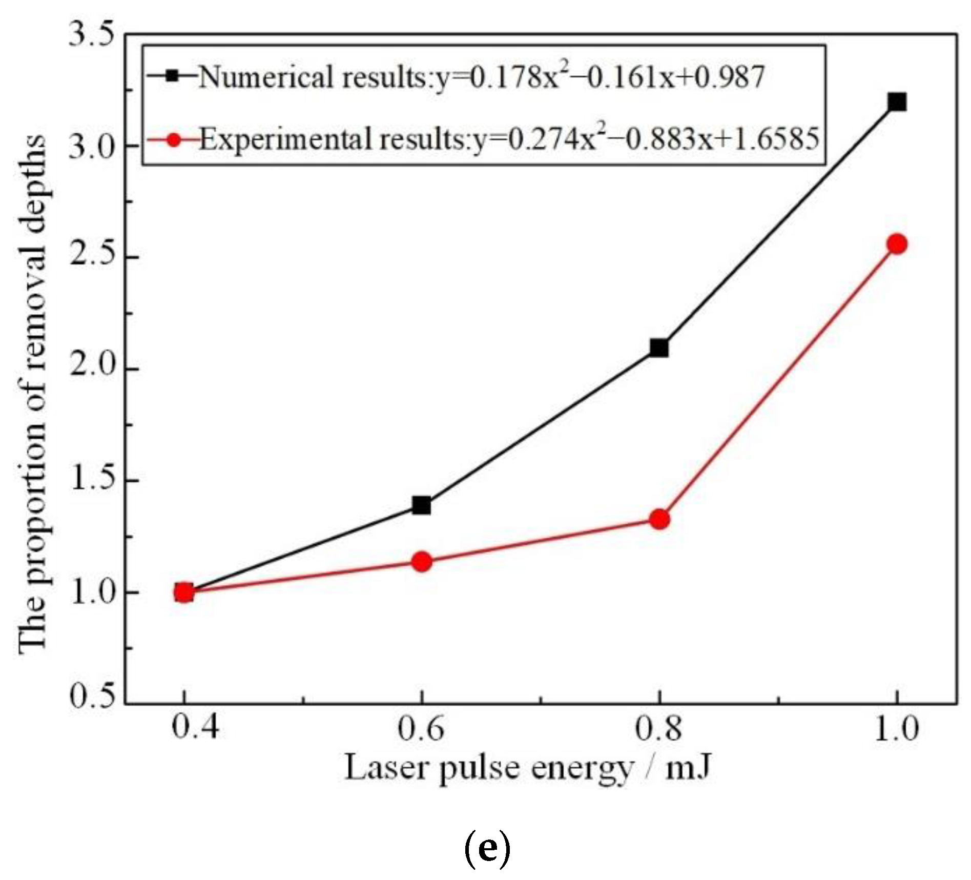
4.2. Influence of Different Laser Pulse Energy on Ablation Depth

The evolutions of maximum temperature under different laser pulse energies were investigated in this paper by numerical simulation. The results are shown in Figure 7. These temperature variations share a similar trend: An extreme temperature value is reached during the laser pulse duration, then the surface layer which exceeds the melting point is peeled by the water jet. Hence, the laser heat flux will be applied to the remaining material. In this stage, a weak balance of surface temperature is achieved by the combined effect of laser and water jet until the end of the pulse duration. Then, a sharp drop in temperature arises whereafter a gradually slow trend begins throughout the rest of one 1/f period. The different maximum temperatures are listed in Figure 7 with the insertion of a red line at the same location (2973.15 K). According to the theory of LWJ machining, the CMCs material removal can only occur in the area above the red line. Obviously, a stronger processing capability could be obtained under a higher laser pulse energy.
To achieve a more reliable numerical result, the processing capabilities of each individual pulse energy were calculated. Figure 8 reveals the cross-section status of the CMCs model after the treatment of LWJ. As demonstrated in Figure 8a, the material of the top surface is peeled with a smooth transition at the edge. The diameter of the overall area is approximately 55 μm with a 50 μm size of the central flat zone. The substrate status at 1.38 × 10⁻⁶s (t = 16 × tp) is shown in Figure 8b. Corresponding to Figure 5g, an annular distribution of high temperature with 1855 K is obtained, which spreads downward to 3 μm on the z-axis. This result indicates that thermal diffusion could be effectively restricted using the method of LWJ. In the last time step of one 1/f period, the substrate temperature is minimized by the heat convection of water and air, as shown in Figure 8c. An annular distribution of temperature similar to Figure 8b is still presented with a diffusion distance of 5–10 μm. However, the maximum temperature is only 494.5 K, which is far below the thermal damage threshold of CMCs and hardly affects the SiC fibers. The central flat zone was adopted as a judgment criterion to evaluate the material removal, a depth of 0.853 μm could be achieved by means of measuring the coordinates.
Furthermore, from Figure 7, it was discovered that the difference among maximum temperatures is able to reach more than 1200 K. The differentiated temperature fields are reflected in the efficiency of material removal. Figure 9 displays the numerical results of CMCs material removal in different laser pulse energies. The ablation depths with 0.4 mJ, 0.6 mJ, 0.8 mJ and 1 mJ are 0.267 μm, 0.371 μm, 0.559 μm, and 0.853 μm, respectively. On the basis of this type of theoretical calculation, one assumption is put forward. In the case of 1 mJ pulse energy and 50 KHz repetition frequency, a micro-hole with a significant machining depth of 41.65 mm and a diameter of 55 μm would be acquired in 1 s. Even though this result occurs in an ideal situation, this finding is somewhat counterintuitive and has few possibilities in the actual experiment.
For this numerical result, there are some possible explanations. Firstly, the water jet serves as a multi-mode fiber to deliver the laser to the surface of the material in the LWJ technique; only the compact section of the water jet can realize a perfect laser transmission [26]. At the initial stage of LWJ machining, the material of the top surface could be removed smoothly. As the processing continues, a pit feature is generated instead of a flat surface. Particularly, the anisotropic fiber braided method will create a more complex interior structure, which could go against the formation of a compact section of the water jet; moreover, turbulence or a broken jet might have emerged. Secondly, the procedure of LWJ machining could be expressed as follows: (1) The water jet of LWJ contacts the material, (2) the temperature of the top surface material rises, (3) the material exceeds the melting point and is peeled from the substrate by the scouring effect of the water jet, (4) slags are ejected with the water flow. So far, the entire LWJ machining process has been accomplished. The vital factor of this procedure is step (4), which means that adequate drainage space is essential for LWJ machining, or the stability of the water jet will be strongly disturbed by the reversed spurting slags and spray. As a result, the CMCs material removal is severely weakened by this negative phenomenon [27]. Therefore, the numerical simulation can hardly reveal actual machining abidingly as time goes on. However, the numerical removal depth of the initial laser pulse could be defined as a judgment criterion to measure the processing capacity of different laser pulse energies. It can be seen from Figure 9 that the proportion of removal depths with 0.4 mJ, 0.6 mJ, 0.8 mJ, and 1 mJ are 1:1.389:2.094:3.195, respectively. To verify the numerical simulation results, a scribing experiment was adopted.

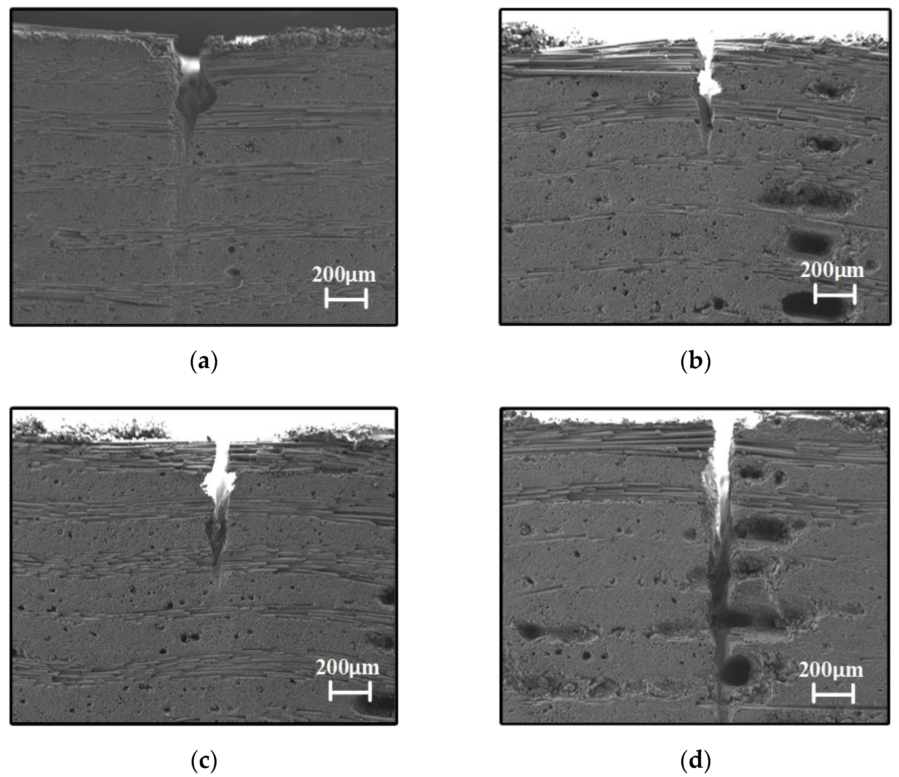
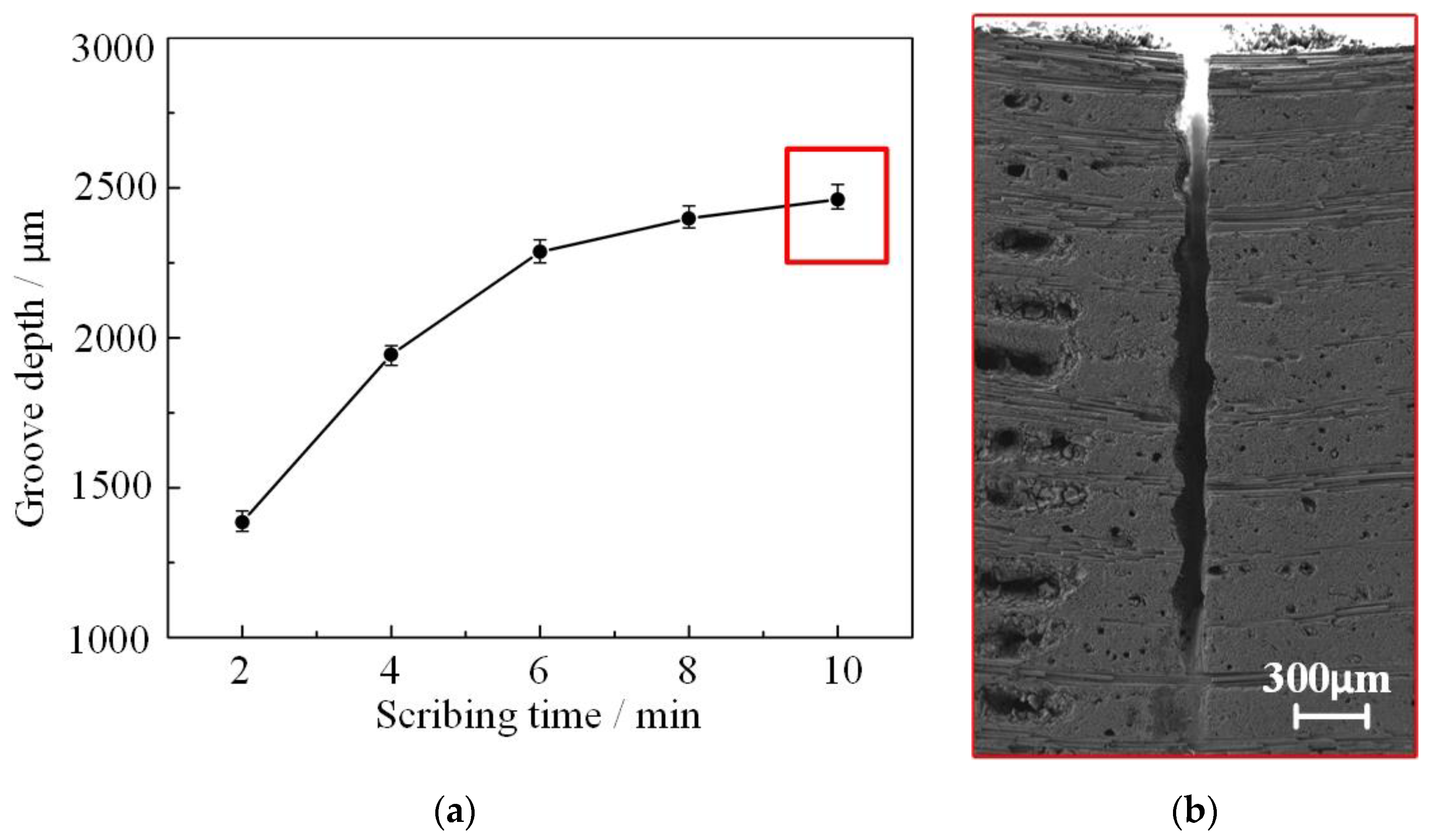
4.3. Scribing Experimantal Results

The scribing results with different laser pulse energies are demonstrated in Figure 10. The same water pressure and laser parameters were selected corresponding to Figure 9. Moreover, the scribing velocity of LWJ was set as 10 mm/s with a 5 mm scribing length. With a uniform processing time of 2 min, the scribing number on the same path of every single groove is 240. As a result, the depth of grooves from low to high was 541 μm, 615 μm, 718 μm, and 1385 μm corresponding to a laser pulse energy of 0.4 mJ, 0.6 mJ, 0.8 mJ and 1 mJ, respectively. According to the scribing results, the proportion of removal depths with 0.4 mJ, 0.6 mJ, 0.8 mJ, and 1 mJ was obtained, demonstrated as 1:1.137:1.327:2.560. These scribing results presented a weaker machining capacity compared to the numerical simulation. According to the analysis above, an increasingly complicated inner structure might serve as the main reason for this deviation, as explained in step (4). However, the numerical and experimental results share a similar variation trend, as shown in Figure 10e.
A further scribing experiment was developed to investigate the ultimate machining capacity of LWJ. With series scribing times of 2 min, 4 min, 6 min, 8 min, and 10 min, as well as a pulse energy of 1 mJ and water pressure of 20 Mpa, the scribing results can be observed in Figure 11. The groove depths of different scribing times were 1385 μm, 1944 μm, 2287 μm, 2398 μm, and 2461 μm, respectively. It can be clearly seen in Figure 11a that the increase in groove depth stagnated after 6 min. This indicates that there is a limited value for the groove depth for single-row scribing. Combining the numerical calculation and experimental results, it states that an environment with expedited drainage space is crucial for LWJ machining. As the further development of the groove, a deep and narrow “V” shape arose with a tapering bottom. Such a feature could weaken the efficacy of LWJ directly, and only a small amount of laser energy could be delivered onto the material before the water jet broke completely. Although CMCs material removal could also be realized in this situation, a limit value was finally reached, as shown in Figure 11b.

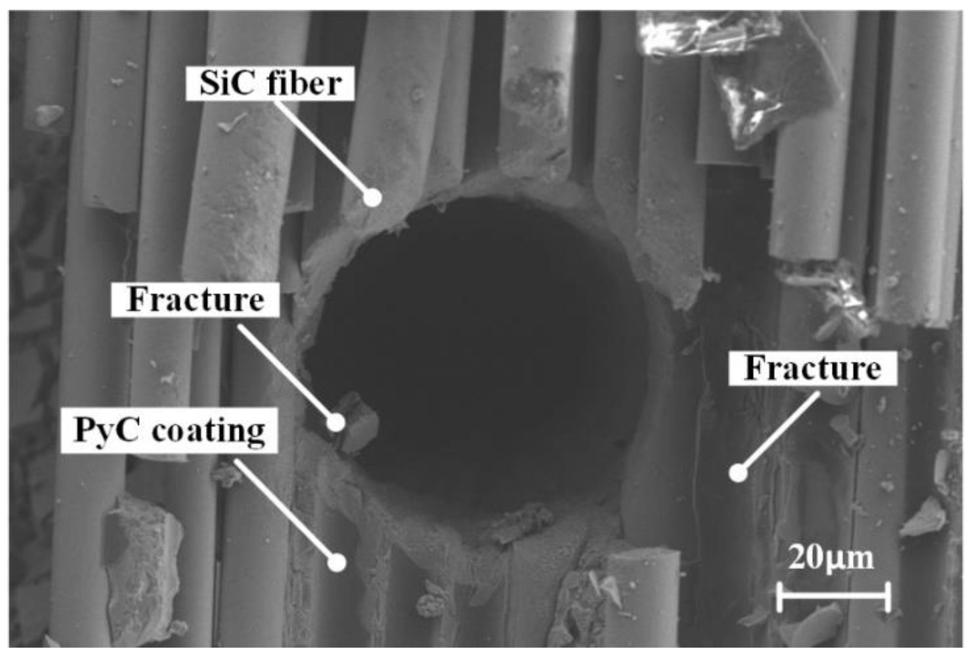
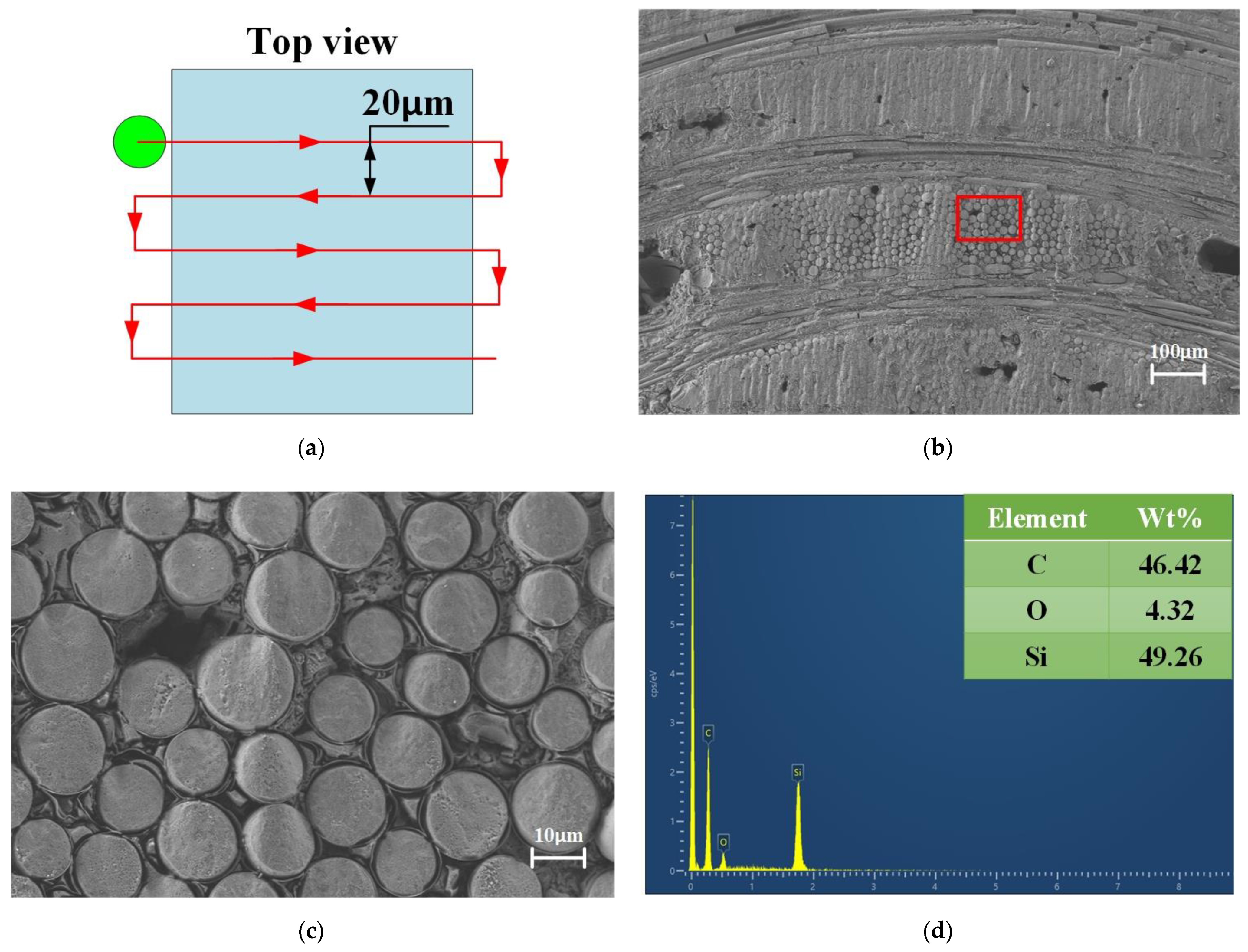
4.4. Morphology of Cutting Surface

According to Section 4.3, a limited groove depth value was shown by single-row scribing. To realize the thorough cutting of CMCs substrate with 3 mm thickness, a multi-row scribing strategy should be taken into consideration. As demonstrated in Figure 12a, the shape of LWJ is represented by a green circle with a diameter of 50 μm. The distance between the lines is 20 μm and the holistic path width is 150 μm. In addition, the overlapping width between the two neighboring scribing paths is 30 μm. The morphology of CMCs cross-section is demonstrated in Figure 12b,c. The horizontal and vertical SiC fibers can be seen clearly without obvious ablation traces and the recast layer in the SEM images. In particular, the phenomenon of pulling out of SiC fibers and delamination could hardly be observed in the enlarged cross-section morphology. This result states that multi-row scribing can provide enough drainage space for LWJ machining. Thus, full advantage of the laser energy could be taken in the multi-row scribing rather than disregarding this completely. In addition, the EDS test using sweep mode at the machined surface provided a significant result which proves the LWJ technique could prevent oxidation of processed materials due to its unique advantages.

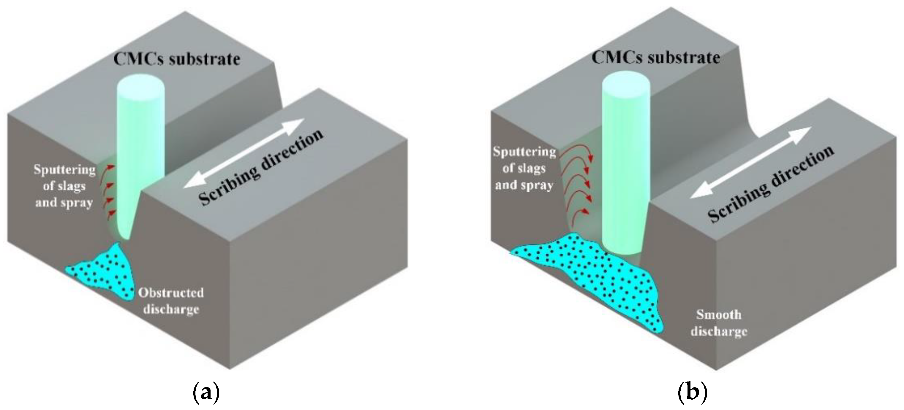
4.5. Mechanism of CMCs Machining with LWJ

Compared to conventional laser machining, the main characteristic of LWJ is that a compact section of the water jet is essential to deliver the laser energy as an optical fiber. Moreover, although the length of the compact section can reach 30–100 mm, it is only a non-functioning jet type. Once the water jet contacts the workpiece, the situation changes. Especially going deep inside the material, the stable delivery of the water jet would be strongly disturbed by the complex processing environment, which would further affect the normal processing of LWJ. Evidence of this phenomenon has been demonstrated in Section 4.2. As shown in Figure 13a, the material of the top surface has reached its melting point by laser ablation. In general, sublimation arises with high temperatures. However, due to the scouring effect of the water jet, a sublimation steam atmosphere and recast layer were not generated. Finally, the slags would be discharged from the substrate material by the water flow. Previous research has shown that a drainage circle in the millimeter range will be generated on the material surface by a high-speed water jet [16]. The water flow in this circle could maintain a fairly high speed which provided an effect of sweeping out the slag. Under the circumstances of single-row scribing, the size of the processed feature corresponds roughly to the water jet. Hence, the high-speed water flow and slags would impact the wall surface of the groove in which the stability of the water jet is destroyed by sputtering. The main consequence of the sputtering effect is that only a few laser energies in the central area could be delivered onto the material. However, a limit value of groove depth would ultimately be reached by means of single-row scribing. In simple terms, without the discharging of the slags and water flow from the previous stage, the LWJ can hardly afford the full effect of machining. Furthermore, the complex interior structure of CMCs can also restrict the processing capacity of LWJ.
In contrast, the multi-row scribing strategy not only offers enough drainage space for water flow and slags but also controls the “near wall effect” [28]. As demonstrated in Figure 13b, the slags could be smoothly discharged with the water flow from both sides of the groove, allowing each individual laser pulse to be utilized to the maximum extent. Meanwhile, the groove with a size much larger than the water jet provides cushion space for the sputtering of slags and water flow. As a result, the probability of the water jet being impacted is greatly reduced, and the stable machining of LWJ is guaranteed. It should be pointed out that the “near wall effect” can also hardly be avoided using the multi-row scribing strategy. The water jet would be inevitably distributed at both sides of the groove, which results in a processed feature—ultimately with a slight slope. It may be concluded that a processed feature with better quality can be realized by a greater holistic path width strategy. However, processing efficiency will certainly be reduced by this method. As a whole, whether the machining capacity of LWJ could be applied adequately, the stability of the water jet has a leading status. The machining consistency of each individual laser pulse can be ensured by an excellent, non-interfering processing scenario.

5. Conclusions

In this paper, a three-dimensional FEM model was established using COMSOL Multiphysics to analyze the distribution and evolution of the temperature field on a material surface. With the combination of numerical simulation and experimental results, the influence of different laser pulse energies on machining capacity was explored. Meanwhile, the characteristics of single-tow and multi-row scribing methods were compared. The detailed conclusions are as follows:
(1)
The thermal damage of CMCs machining could be restricted effectively by LWJ. Under the effect of forced cooling and scouring, the material removal was confined to a zone of a similar size to the water jet. The difference in maximum temperature on the CMCs surface under various laser pulses could reach up to more than 1200 K which led to a different material removal depth. Although there is a difference in value between the numerical simulation and actual experiment, the proportion reached an agreement.
(2)
A single-row scribing experiment using LWJ was carried out with a limit depth of 2.461 mm. To realize the complete discontinuation of CMCs with 3 mm thickness, the multi-row scribing method was adopted. According to the morphology analysis of the cut surface and EDS test results, a series of LWJ advantages has been discussed. For example, the HAZ and recast layer was hardly observed, as well as pulling out of SiC fibers and delamination.
Finally, future work will be concentrated on FEM of full-size CMCs to explore the fracture behavior of SiC fibers and their PyC coating, which will clarify the action principle between LWJ and CMCs from a micromechanics aspect.

Author Contributions

Conceptualization, B.C. and Y.L.; methodology, B.C. and Y.L.; software, B.C.; validation, B.C., Y.L. and Y.D.; formal analysis, B.C. and Y.D.; investigation, B.C. and Y.L.; resources, L.Y. and Y.D.; data curation, B.C.; writing—original draft preparation, B.C.; writing—review and editing, B.C. and Y.D.; visualization, B.C. and Y.L.; supervision, L.Y. and Y.D.; project administration, L.Y. and Y.D. funding acquisition, L.Y. and Y.D. All authors have read and agreed to the published version of the manuscript.

Funding

This research was supported by National Key R&D Program of China (No.2018YFB1107600), National Science and Technology Major Project (No. 2019-VII-0009-0149).

Institutional Review Board Statement

Not applicable.

Informed Consent Statement

Not applicable.

Acknowledgments

The authors would like to thank Yanchao Guan, for the SEM images.

Conflicts of Interest

The authors declare no conflict of interest.

References

  1. DiCarlo, J.A. Advances in SiC/SiC Composites for Aero-Propulsion. Ceramic Matrix Composites; John Wiley & Sons, Inc.: Hoboken, NJ, USA, 2014; pp. 217–235. [Google Scholar]
  2. Naslain, R. Design, preparation and properties of non-oxide CMCs for application in engines and nuclear reactors: An overview. Compos. Sci. Technol. 2004, 64, 155–170. [Google Scholar] [CrossRef]
  3. Sauder, C. Ceramic matrix composites: Nuclear applications. In Ceramic Matrix Composites; John Wiley & Sons, Inc.: Hoboken, NJ, USA, 2014; pp. 609–646. [Google Scholar]
  4. Diaz, O.G.; Axinte, D.; Butler-Smith, P.; Novovic, D. On understanding the microstructure of SiC/SiC Ceramic Matrix Composites (CMCs) after a material removal process. Mater. Sci. Eng. A 2018, 743, 1–11. [Google Scholar] [CrossRef]
  5. Zhang, Y.; Hu, H.; Ren, J. Effect of the surface microstructure of SiC inner coating on the bonding strength and ablation resistance of ZrB2-SiC coating for C/C composites. Ceram. Int. 2016, 42, 18657–18665. [Google Scholar] [CrossRef]
  6. Feng, P.; Wang, J.; Zhang, J.; Zheng, J. Drilling induced tearing defects in rotary ultrasonic machining of C/SiC composites. Ceram. Int. 2017, 43, 791–799. [Google Scholar] [CrossRef]
  7. Mishra, S.; Yadava, V. Modeling and optimization of laser beam percussion drilling of nickel-based superalloy sheet using Nd: YAG laser. Opt. Laser. Eng. 2013, 51, 681–695. [Google Scholar] [CrossRef]
  8. Wei, C.; Zhao, L.; Hu, D.; Ni, J. Electrical discharge machining of ceramic matrix composites with ceramic fiber reinforcements. Int. J. Adv. Manuf. Technol. 2012, 64, 187–194. [Google Scholar] [CrossRef]
  9. Li, W.; Zhang, R.; Liu, Y.; Wang, C.; Wang, J.; Yang, X.; Cheng, L. Effect of different parameters on machining of SiC/SiC composites via pico-second laser. Appl. Surf. Sci. 2015, 364, 378–387. [Google Scholar] [CrossRef]
  10. Hashish, M.; Kotchon, A.; Ramulu, M. Status of AWJ machining of CMCS and hard materials. In Proceedings of the INTERTECH 2015—An International Technical Conference on Diamond, Cubic Boron Nitride and their Applications, Indianapolis, IN, USA, 19–20 May 2015. [Google Scholar]
  11. Richerzhagen, B. Interferometer for measuring the absolute refractive index of liquid water as a function of temperature at 1064 μm. Appl. Opt. 1996, 35, 1650–1653. [Google Scholar] [CrossRef]
  12. Kray, D.; Hopman, S.; Spiegel, A.; Richerzhagen, B.; Willeke, G.P. Study on the edge isolation of industrial silicon solar cells with waterjet-guided laser. Sol. Energy Mater. Sol. Cells 2007, 91, 1638–1644. [Google Scholar] [CrossRef]
  13. Li, C.Q.; Yan, L.J.; Wang, Y. Simulation on Drilling with Water-Jet Guided Laser. Appl. Mech. Mater. 2012, 151, 7–12. [Google Scholar] [CrossRef]
  14. Porter, J.A.; Louhisalmi, Y.A.; Karjalainen, J.A.; Füger, S. Cutting thin sheet metal with a water jet guided laser using various cutting distances, feed speeds and angles of incidence. Int. J. Adv. Manuf. Technol. 2006, 33, 961–967. [Google Scholar] [CrossRef]
  15. Hale, G.M.; Querry, M.R. Optical Constants of Water in the 200-nm to 200-μm Wavelength Region. Appl. Opt. 1973, 12, 555–563. [Google Scholar] [CrossRef] [PubMed]
  16. Cheng, B.; Ding, Y.; Li, Y.; Li, J.; Xu, J.; Li, Q.; Yang, L. Coaxial helical gas assisted laser water jet machining of SiC/SiC ceramic matrix composites. J. Mater. Process. Technol. 2021, 293, 117067. [Google Scholar] [CrossRef]
  17. Li, C.-F.; Johnson, D.B.; Kovacevic, R. Modelling of heat transfer in waterjet guided laser drilling of silicon. Proc. Inst. Mech. Eng. Part B J. Eng. Manuf. 2003, 217, 583–600. [Google Scholar] [CrossRef]
  18. Wagner, F.R.; Boillat, C.; Buchilly, J.-M.; Spiegel, A.; Vago, N.; Richerzhagen, B. High-speed cutting of thin materials with a Q-switched laser in a water-jet versus conventional laser cutting with a free running laser. In Proceedings of the Photon Processing in Microelectronics and Photonics II, International Society for Optics and Photonics, San Jose, CA, USA, 17 October 2003; Volume 4977, pp. 70–74. [Google Scholar]
  19. Wagner, F.R.; Hu, W.; Spiegel, A.; Vago, N.; Richerzhagen, B. High-speed singulation of electronic packages using a frequency-doubled Nd: YAG laser in a water jet and realization of a 200-W green laser. In Proceedings of the Photon Processing in Microelectronics and Photonics II, International Society for Optics and Photonics, San Jose, CA, USA, 17 October 2003; Volume 4977, pp. 563–568. [Google Scholar]
  20. Couty, P.; Wagner, F.R.; Hoffmann, P.W. Laser coupling with a multimode water-jet waveguide. Opt. Eng. 2005, 44, 068001. [Google Scholar] [CrossRef]
  21. Webb, B.; Ma, C.-F. Single-Phase Liquid Jet Impingement Heat Transfer. Adv. Heat Transf. 1995, 26, 105–217. [Google Scholar] [CrossRef]
  22. Funada, T.; Wang, J.; Daniel, D. Viscous Potential Flow Analysis of Stress-Induced. At. Spray 2006, 16, 763–776. [Google Scholar] [CrossRef] [Green Version]
  23. Pek, E.K.; Brethauer, J.; Cahill, D.G. High spatial resolution thermal conductivity mapping of SiC/SiC composites. J. Nucl. Mater. 2020, 542, 152519. [Google Scholar] [CrossRef]
  24. Chen, J.; An, Q.; Ming, W.; Chen, M. Investigations on continuous-wave laser and pulsed laser induced controllable ablation of SiCf/SiC composites. J. Eur. Ceram. Soc. 2021, 41, 5835–5849. [Google Scholar] [CrossRef]
  25. Jing, X.; Cheng, Z.; Niu, H.; Yang, X.; Shi, D. Deformation and rupture behaviors of SiC/SiC under creep, fatigue and dwell-fatigue load at 1300 °C. Ceram. Int. 2019, 45, 21440–21447. [Google Scholar] [CrossRef]
  26. Richerzhagen, B.; Plankensteiner, M.; Kling, N.U.; Stay, K.; Brulé, A. Saw + LMJ: A hybrid semiconductor dicing solution. In Proceedings of the Laser-Based Micro-and Nanopackaging and Assembly II, San Jose, CA, USA, 22–24 January 2008; International Society for Optics and Photonics: Bellingham, WA, USA, 2008; Volume 6880, p. 688005. [Google Scholar]
  27. Mullick, S.; Madhukar, Y.K.; Roy, S.; Nath, A.K. An investigation of energy loss mechanisms in water-jet assisted underwater laser cutting process using an analytical model. Int. J. Mach. Tools Manuf. 2015, 91, 62–75. [Google Scholar] [CrossRef]
  28. Diboine, J.; Martin, R.; Bruckert, F.; Diehl, H.; Richerzhagen, B. Towards near-net shape micro-machining of aerospace materials by means of a water jet-guided laser beam. In Proceedings of the Lasers in Manufacturing Conference, Munich, Germany, 26–29 June 2017. [Google Scholar]
Figure 1. Schematic of LWJ machining system.
Applsci 12 01214 g001
Figure 2. (a) Schematic and (b) actual morphology of CMCs; (c) detailed morphology of single SiC fiber; (d) actual braided structure of CMCs with EDS test result before processing.
Applsci 12 01214 g002aApplsci 12 01214 g002b
Figure 3. Energy distribution of (a) traditional laser and (b) LWJ.
Applsci 12 01214 g003
Figure 4. Numerical simulation model of CMCs (a) geometry and (b) mesh generation.
Applsci 12 01214 g004
Figure 5. Spatial and temporal distribution of temperature during LWJ machining: (a) t = 4.3 × 10⁻⁸ s; (b) t = 8.6 × 10⁻⁸ s; (c) t = 1.72 × 10⁻⁷ s; (d) t = 3.44 × 10⁻⁷ s; (e) t = 5.16 × 10⁻⁷ s; (f) t = 8.6 × 10⁻⁷ s; (g) t = 1.38 × 10⁻⁶ s; (h) t = 1.99 × 10⁻⁵ s.
Applsci 12 01214 g005aApplsci 12 01214 g005b
Figure 6. The morphology of single-dot experiment with LWJ.
Applsci 12 01214 g006
Figure 7. Evolution of maximum temperature of CMCs surface in different laser pulse energies: (a) 0.4 mJ; (b) 0.6 mJ; (c) 0.8 mJ; (d) 1 mJ.
Applsci 12 01214 g007aApplsci 12 01214 g007b
Figure 8. Status analysis of material removal with LWJ at (a) t = 4.3 × 10⁻⁸ s; (b) t = 1.38 × 10⁻⁶ s; (c) t = 1.99 × 10⁻⁵ s.
Applsci 12 01214 g008
Figure 9. Numerical results of CMCs material removal in different laser pulse energies.
Applsci 12 01214 g009
Figure 10. Groove depths under different laser pulse energies: (a) 0.4 mJ; (b) 0.6 mJ; (c) 0.8 mJ; (d) 1.0 mJ; (e) variation trend of numerical and experimental results.
Applsci 12 01214 g010aApplsci 12 01214 g010b
Figure 11. Extreme scribing depth test of LWJ. (a) The variation in scribing depth with time; (b) the extreme scribing depth.
Applsci 12 01214 g011
Figure 12. Thorough cutting of CMCs with multi-row scribing strategy. (a) Schematic of multi-row scribing method; (b) cross-section of cutting surface of CMCs; (c) partially enlarged cross-section morphology; (d) EDS test using sweep mode at the machined surface.
Applsci 12 01214 g012
Figure 13. The distinction between (a) single-row and (b) multi-row scribing.
Applsci 12 01214 g013
Table 1. Main output parameters of laser source.
ParameterWavelengthPulse DurationRepetition RateAverage PowerPulse EnergyBeam Diameter
Value532 nm86 ns50 KHz50 W (max)1 mJ (max)2 mm (1/e2)
Table 2. Detailed parameters of CMCs.
ParameterValue
Density2060 kg/m3
Diameter of SiC fiber8–15 μm
Thickness of PyC coating1 μm
Thickness of CMCs material3 mm
Thermal conductivity5.843 W/m·K
Specific heat capacity2767 J/kg·K
Ablation temperature2973.15 K
Heat of sublimation7.471 × 106 J/kg
Publisher’s Note: MDPI stays neutral with regard to jurisdictional claims in published maps and institutional affiliations.

