
A New Design Method of Shield Tunnel Based on the Concept of Minimum Bending Moment


Abstract
:1. Introduction
2. Analysis of the Pressure Exerted on the Cross-Section of the Shield Tunnel
2.1. Hypothesis of the Earth Pressure Acting on the Shield Tunnel
2.2. The Analysis of the Pressure Exerted on the Shield Tunnel
3. The Design and Calculation of the Zero Bending Moment Shield Tunnel Cross-Section
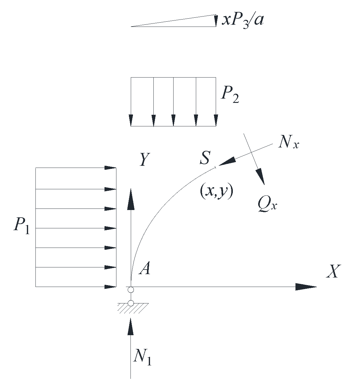
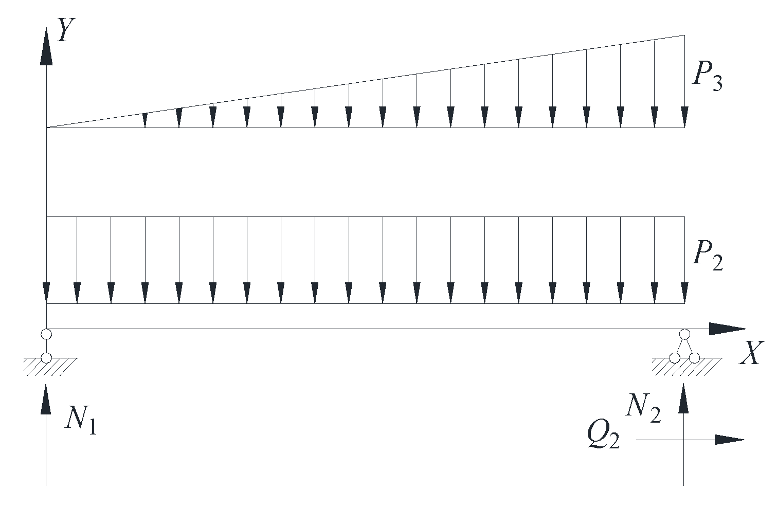
3.1. The Calculation of the Rational Axis for Shield Tunnel Cross-Section
3.2. The Calculation of the Horizontal Diameter of the Zero Bending Moment Shield Tunnel
3.3. The Calculation of the Internal Force of the Zero Bending Moment Shield Tunnel
4. Cross-Section Design and Case Analysis for Minimum Bending Moment Shield Tunnel in Soft Soil Area
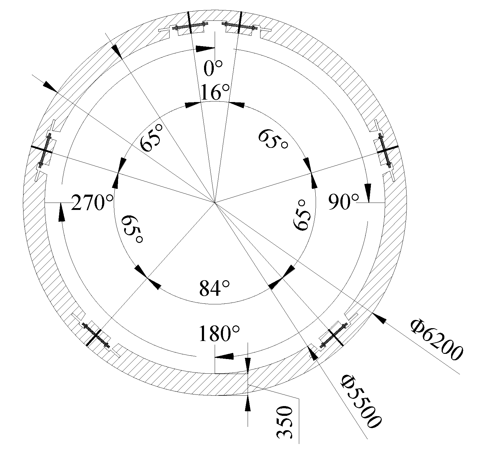
4.1. Brief Introduction for Shanghai Metro Shield Tunnel
4.2. Analysis for Cross-Section Key Parameters of Zero Bending Moment Shield Tunnel
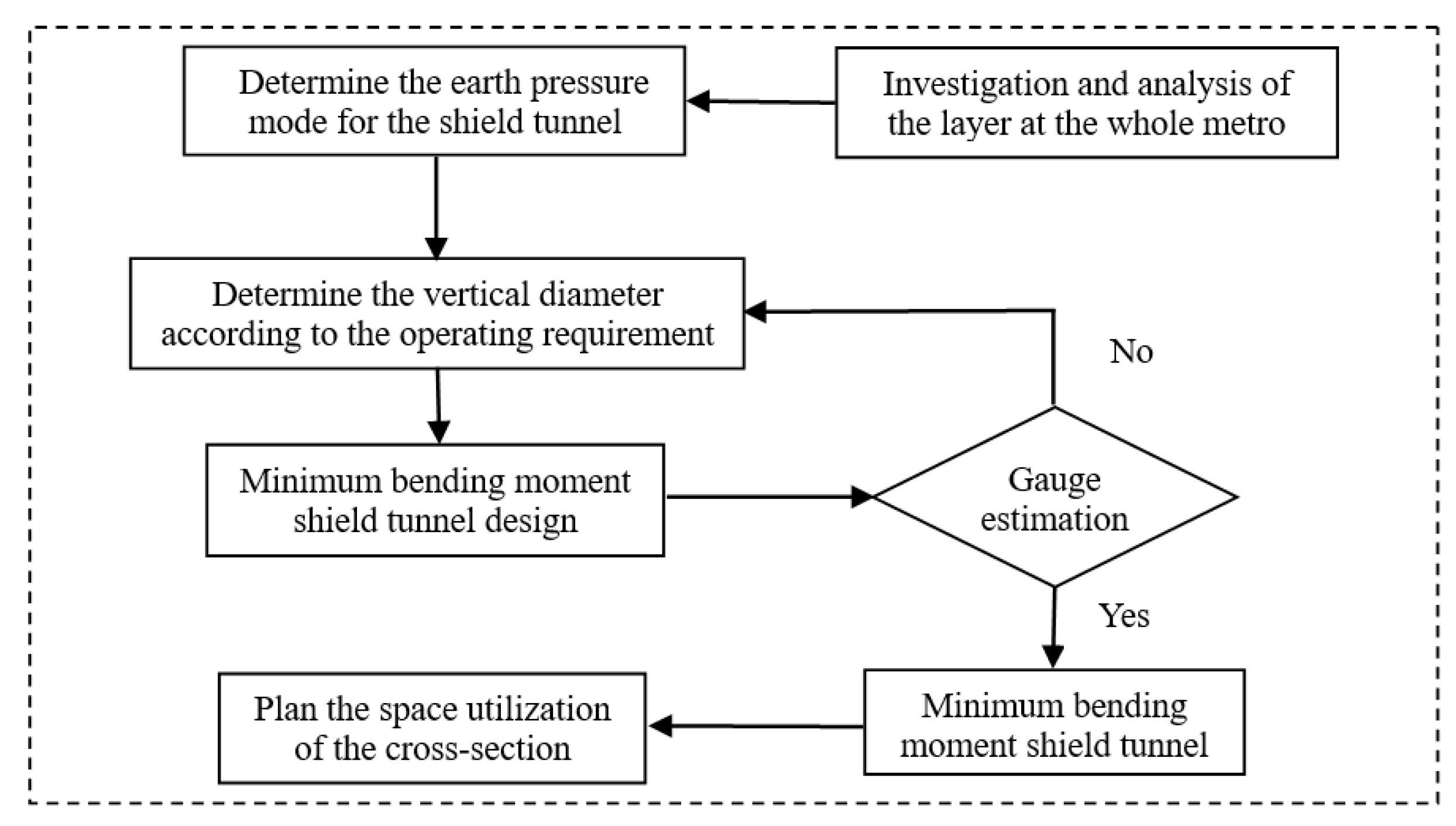
4.3. Cross-Section Design for the Minimum Bending Moment Shield Tunnel
4.4. Case Analysis for Minimum Bending Moment Shield Tunnel
5. Conclusions
- (1)
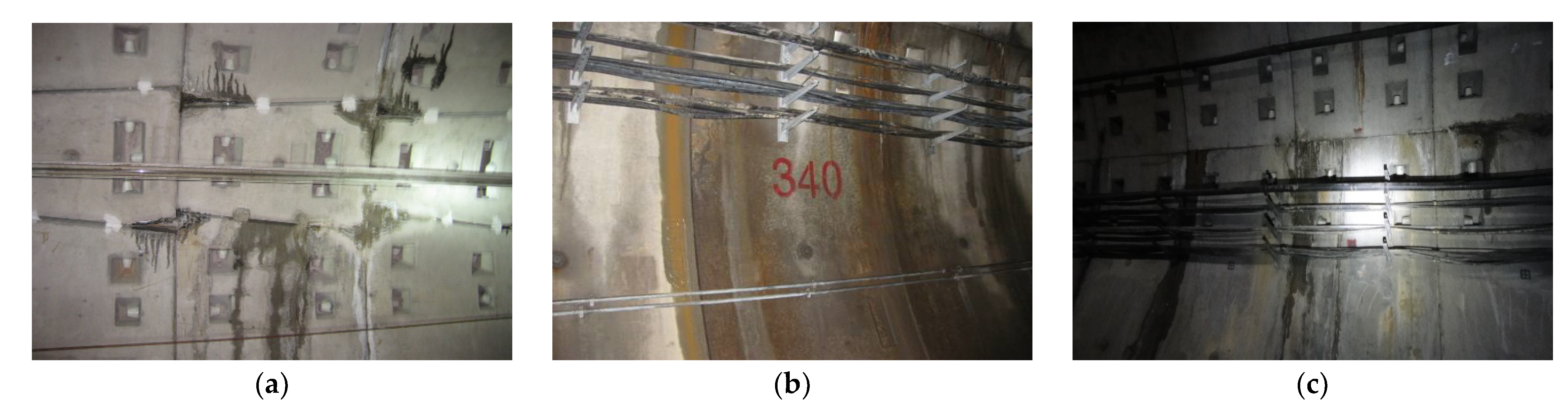
- Given that the bending moment of the cross-section of the shield tunnel constructed in the soft soil area tends to easily lead to beyond-limit oval deformation of the cross-section and induce diseases and waterproof failure in terms of the segment joint structure, this article puts forward the concept of designing a zero bending moment shield tunnel for the first time.
- (2)
- Based on the characteristics of the surrounding rocks of the tunnel and rational assumption conditions, this article obtains the structural and mechanical calculation model of the rational axis for the zero bending moment shield tunnel and the expression of the rational axis. In addition, the internal force and key parameters calculating the equations of the zero bending moment shield tunnel are advised here in this article.
- (3)
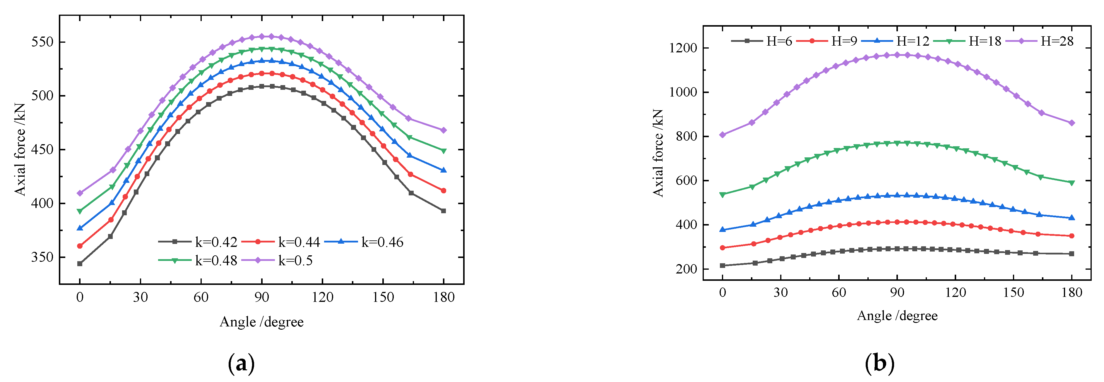
- Taking the shield tunnel constructed in the Shanghai soft soil area as an example, we designed and analyzed the zero bending moment shield tunnel. The results indicate that if the vertical diameter a remains the same, as the lateral earth pressure coefficient k increases, the center horizontal diameter b and the maximum horizontal diameter c both increase, but still less than the vertical diameter a; however, if the center horizontal diameter b remains the same, as the buried height of the tunnel increases, the vertical diameter a increases and the shear force of the zero bending moment shield tunnel is zero.
- (4)
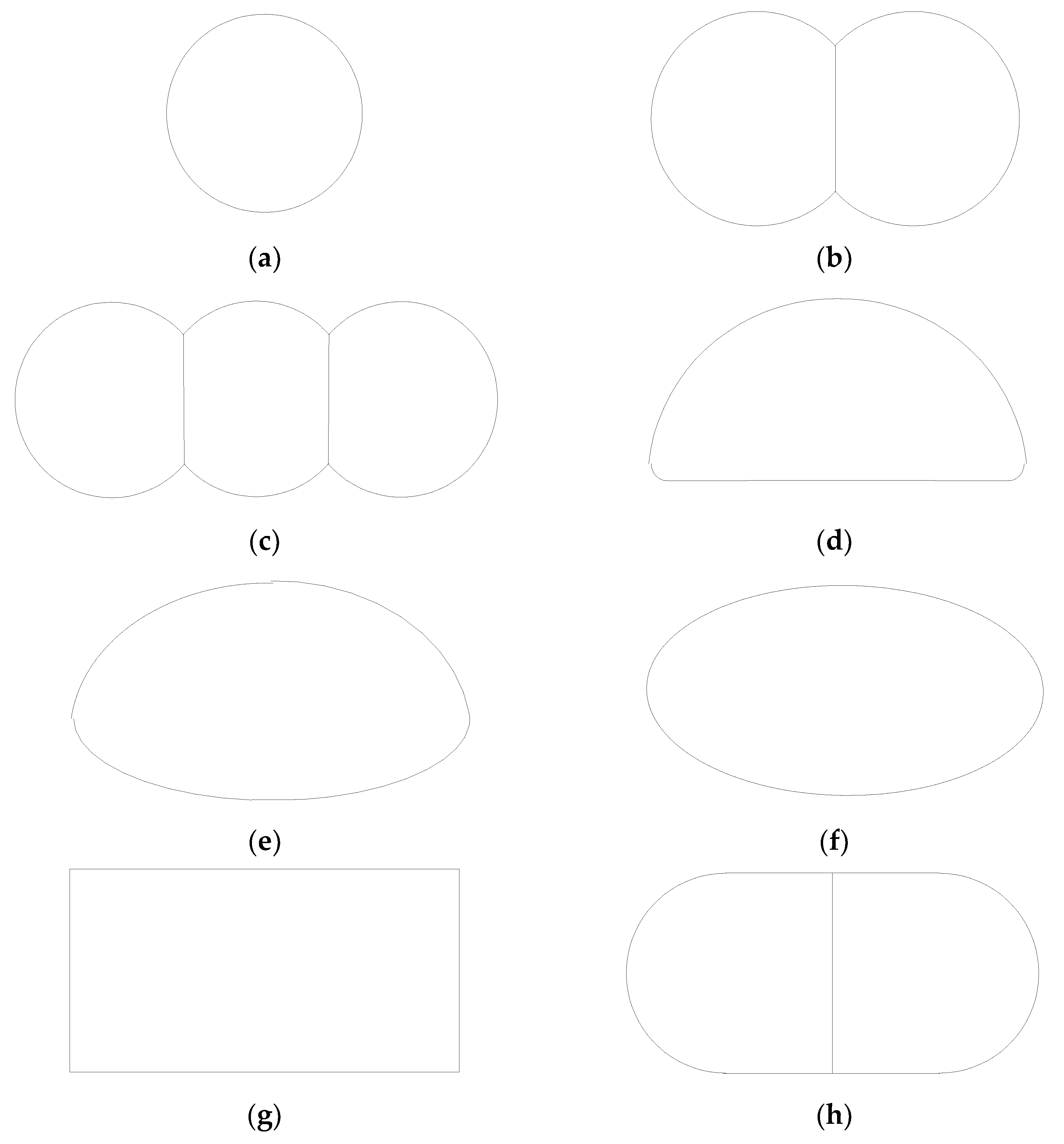
- Normally, one metro line can only use one shield tunnel with one cross-section shape. Given this, the shield tunnel cross-section design methods and procedures based on the minimum bending moment are proposed here. We took the parameters of the soils that one metro line shield tunnel in Shanghai passes through as an example and used the weighted average to obtain the minimum bending moment tunnel cross-section of that metro line. The numerical simulation analysis indicates that the similar vertical elliptical cross-section shield tunnel features a significantly smaller bending moment compared to that of the circular shield tunnel.
Author Contributions
Funding
Institutional Review Board Statement
Informed Consent Statement
Data Availability Statement
Conflicts of Interest
References
- Japan Society of Civil Engineers. Japanese Standard for Shield Tunneling; Japan Society of Civil Engineers: Tokyo, Japan, 1996. [Google Scholar]
- Japan Society of Civil Engineers. Standard Specifications for Tunneling: Shield Tunnels; Japan Society of Civil Engineers: Tokyo, Japan, 2006. [Google Scholar]
- Yukinori, K. Present status and technology of shield tunneling method in Japan. Tunn. Undergr. Space Technol. 2003, 18, 145–159. [Google Scholar] [CrossRef]
- He, C.; Wang, B. Research progress and development trends of highway tunnels in China. J. Mod. Transp. 2013, 21, 209–223. [Google Scholar] [CrossRef] [Green Version]
- Mashimo, H.; Ishimura, T. Evaluation of the load on shield tunnel lining in gravel. Tunn. Undergr. Space Technol. 2003, 18, 233–241. [Google Scholar] [CrossRef]
- Blom, C.B.M. Design Philosophy of Concrete Linings for Tunnels in Soft Soils. Ph.D. Thesis, Technische Universiteit Delft, Delft, The Netherlands, 2002. [Google Scholar]
- Bian, X.; Hong, Z.S.; Ding, J.W. Evaluating the effect of soil structure on the ground response during shield tunnelling in Shanghai soft clay. Tunn. Undergr. Space Technol. 2016, 58, 120–132. [Google Scholar] [CrossRef]
- Vu, M.N.; Broere, W. Structural design model for tunnels in soft soils: From construction stages to the long-term. Tunn. Undergr. Space Technol. 2018, 78, 16–26. [Google Scholar] [CrossRef]
- Working Group No. 2; International Tunnelling Association. Guidelines for the design of shield tunnel lining. Tunn. Undergr. Space Technol. 2000, 15, 303–331. [Google Scholar] [CrossRef]
- General Administration of Quality Supervision, Inspection and Quarantine of the People’s Republic of China. Code for Design of Metro GB 50157-2013; China Standards Press: Beijing, China, 2013. [Google Scholar]
- Ding, W.Q.; Gong, C.J.; Mosalam, K.M.; Soga, K. Development and application of the integrated sealant test apparatus for sealing gaskets in tunnel segmental joints. Tunn. Undergr. Space Technol. 2017, 63, 54–68. [Google Scholar] [CrossRef]
- Gong, C.J.; Ding, W.Q.; Mosalam, K.M.; Selim, G.; Soga, K. Comparison of the structural behavior of reinforced concrete and steel fiber reinforced concrete tunnel segmental joints. Tunn. Undergr. Space Technol. 2017, 68, 38–57. [Google Scholar] [CrossRef]
- Do, N.A.; Dias, D.; Oreste, P.; Djeran-Maigre, I. The behaviour of the segmental tunnel lining studied by the hyperstatic reaction method. Eur. J. Environ. Civ. Eng. 2014, 18, 489–510. [Google Scholar] [CrossRef]
- Huang, Z.; Fu, H.L.; Chen, W.; Zhang, J.B.; Huang, H.W. Damage detection and quantitative analysis of shield tunnel structure. Autom. Constr. 2018, 94, 303–316. [Google Scholar] [CrossRef]
- Huang, D.W.; Zhou, S.H.; Feng, Q.S.; Liu, L.Y.; Zhang, P.F. Optimization for the longitudinal joint of metro shield tunnel under straight joint assembling in soft soli area. China Railw. Sci. 2017, 38, 62–69. (In Chinese) [Google Scholar] [CrossRef]
- Gong, C.J.; Ding, W.Q.; Soga, K.; Mosalam, K.M. Failure mechanism of joint waterproofing in precast segmental tunnel linings. Tunn. Undergr. Space Technol. 2019, 84, 334–352. [Google Scholar] [CrossRef]
- Gong, C.J.; Ding, W.Q.; Xie, D.W. Parametric investigation on the sealant behavior of tunnel segmental joints under water pressurization. Tunn. Undergr. Space Technol. 2020, 97, 103231. [Google Scholar] [CrossRef]
- Lei, M.F.; Zhu, B.B.; Gong, C.J.; Ding, W.Q.; Liu, L.H. Sealing performance of a precast tunnel gasketed joint under high hydrostatic pressures: Site investigation and detailed numerical modeling. Tunn. Undergr. Space Technol. 2021, 115, 104082. [Google Scholar] [CrossRef]
- Teachavorasinskun, S.; Chub-Uppakarn, T. Influence of segmental joints on tunnel lining. Tunn. Undergr. Space Technol. 2010, 25, 490–494. [Google Scholar] [CrossRef]
- Guan, Z.C.; Deng, T.; Wang, G.; Jiang, Y.J. Studies on the key parameters in segmental lining design. J. Rock Mech. Geotech. Eng. 2015, 7, 674–683. [Google Scholar] [CrossRef] [Green Version]
- Caratelli, A.; Meda, A.; Rinaldi, Z.; Giuliani-Leonardi, S.; Renault, F. On the behavior of radial joints in segmental tunnel linings. Tunn. Undergr. Space Technol. 2018, 71, 180–192. [Google Scholar] [CrossRef]
- Wang, F.; Shi, J.K.; Huang, H.W.; Zhang, D.M. Modified analytical solution of shield tunnel lining considering nonlinear bending stiffness of longitudinal joint. Tunn. Undergr. Space Technol. 2020, 106, 103625. [Google Scholar] [CrossRef]
- Bi, X.L.; Liu, X.; Wang, X.Z.; Lu, L.; Yang, Z.H. Experimental investigation on the ultimate bearing capacity of continuous-jointed segmental tunnel linings. China Civ. Eng. J. 2014, 47, 117–127. (In Chinese) [Google Scholar] [CrossRef]
- Möller, S. Tunnel Induced Settlements and Structural Forces in Linings. Ph.D. Thesis, University of Stuttgart, Stuttgart, Germany, 2006. [Google Scholar]
- Li, X.J.; Yan, Z.G.; Wang, Z.; Zhu, H.H. Experimental and analytical study on longitudinal joint opening of concrete segmental lining. Tunn. Undergr. Space Technol. 2015, 46, 52–63. [Google Scholar] [CrossRef]
- Arnau, O.; Molins, C. Three dimensional structural response of segmental tunnel linings. Eng. Struct. 2012, 44, 210–221. [Google Scholar] [CrossRef] [Green Version]
- Huang, D.W.; Zhou, S.H.; Lai, G.Q.; Feng, Q.S.; Liu, L.Y. Mechanism and character for deterioration of shield tunnel under surface surcharge. Chin. J. Geotech. Eng. 2017, 39, 1173–1181. (In Chinese) [Google Scholar] [CrossRef]
- Di, H.G.; Zhou, S.H.; Yao, X.P.; Tian, Z.Y. In situ grouting tests for differential settlement treatment of a cut-and-cover metro tunnel in soft soils. Bull. Eng. Geol. Environ. 2021, 80, 6415–6427. [Google Scholar] [CrossRef]
- Hao, X.J.; Zhang, Q.; Sun, Z.W.; Wang, S.H.; Yang, K.; Ren, B.; Yu, G.F.; Zhou, W.; Chen, B.L.; Zhang, X.Y. Effects of the major principal stress direction respect to the long axis of a tunnel on the tunnel stability: Physical model tests and numerical simulation. Tunn. Undergr. Space Technol. 2021, 114, 103993. [Google Scholar] [CrossRef]
- Kumar, J.; Jain, H. Elasto-plastic ground settlement response and stability of single and twin circular unsupported and supported tunnels. Transp. Geotech. 2021, 30, 100620. [Google Scholar] [CrossRef]


| Soil Layer | Unit Weight/kN/m3 | Moisture Content/% | Void Ratio | Liquid Limit/% | Plastic Limit/% | Cohesion/kPa | Internal Friction Angle/° | Compression Modulus/MPa | Poisson Ratio |
|---|---|---|---|---|---|---|---|---|---|
| ③ Mucky silty clay | 19.6 | 39.7 | 1.123 | 35.4 | 20.5 | 9 | 16.5 | 3.36 | 0.3 |
| ④ Mucky clay | 18.8 | 49.4 | 1.392 | 43.2 | 23 | 13 | 10.5 | 2.27 | 0.33 |
| ⑤ Silty clay | 20.1 | 34.8 | 0.996 | 36.9 | 20.7 | 17 | 14 | 4.27 | 0.31 |
| ⑥ Clay | 20.5 | 23.3 | 0.695 | 34 | 18.5 | 44 | 15.5 | 6.58 | 0.3 |
| H/m | k | P1/kPa | P2/kPa | P3/kPa | a/m | b/m | c/m | N1/kN | N2/kN | N3/kN | Δ/m |
|---|---|---|---|---|---|---|---|---|---|---|---|
| 12 | 0.42 | 222.00 | 93.24 | 46.62 | 6.00 | 4.347 | 4.350 | 326.34 | 372.96 | 482.83 | 0.0997 |
| 12 | 0.44 | 222.00 | 97.68 | 48.84 | 6.00 | 4.450 | 4.452 | 341.88 | 390.72 | 494.19 | 0.0997 |
| 12 | 0.46 | 222.00 | 102.12 | 51.06 | 6.00 | 4.550 | 4.552 | 357.42 | 408.48 | 505.30 | 0.0997 |
| 12 | 0.48 | 222.00 | 106.56 | 53.28 | 6.00 | 4.648 | 4.650 | 372.96 | 426.24 | 516.17 | 0.0997 |
| 12 | 0.50 | 222.00 | 111.00 | 55.50 | 6.00 | 4.743 | 4.746 | 388.50 | 444.00 | 526.81 | 0.0997 |
| H/m | k | P1/kPa | P2/kPa | P3/kPa | a/m | b/m | c/m | N1/kN | N2/kN | N3/kN | Δ/m |
|---|---|---|---|---|---|---|---|---|---|---|---|
| 6 | 0.46 | 111.00 | 51.06 | 51.06 | 6.00 | 4.984 | 4.992 | 204.24 | 255.30 | 277.03 | 0.1652 |
| 9 | 0.46 | 166.50 | 76.59 | 51.06 | 6.00 | 4.699 | 4.703 | 280.83 | 331.89 | 391.52 | 0.1244 |
| 12 | 0.46 | 222.00 | 102.12 | 51.06 | 6.00 | 4.550 | 4.552 | 357.42 | 408.48 | 505.30 | 0.0997 |
| 18 | 0.46 | 333.00 | 153.18 | 51.06 | 6.00 | 4.395 | 4.397 | 510.60 | 561.66 | 732.05 | 0.0713 |
| 28 | 0.46 | 518.00 | 238.28 | 51.06 | 6.00 | 4.282 | 4.282 | 765.90 | 816.96 | 1109.14 | 0.0483 |
| Engineering Condition | P1 | P2 | P3 | l |
|---|---|---|---|---|
| 1 | P1-1 | P2-1 | P3-1 | l1 |
| 2 | P1-2 | P2-2 | P3-2 | l2 |
| 3 | P1-3 | P2-3 | P3-3 | l3 |
| …… | …… | …… | …… | …… |
| n | P1-n | P2-n | P3-n | l4 |
| Engineering Condition | H/m | K | P1/kPa | P2/kPa | P3/kPa | l/m | a/m | b/m | c/m | N1/kN | N2/kN | N3/kN | Δ/m |
|---|---|---|---|---|---|---|---|---|---|---|---|---|---|
| 1 | 7 | 0.429 | 136.50 | 58.56 | 50.19 | 2755 | 6.00 | 4.697 | 4.703 | 225.87 | 276.06 | 320.98 | 0.1489 |
| 2 | 10 | 0.429 | 195.00 | 83.66 | 50.19 | 5933 | 6.00 | 4.481 | 4.484 | 301.16 | 351.35 | 437.20 | 0.1149 |
| 3 | 10 | 0.493 | 195.00 | 96.14 | 57.68 | 4340 | 6.00 | 4.803 | 4.807 | 346.09 | 403.77 | 468.67 | 0.1149 |
| 4 | 13 | 0.429 | 253.50 | 108.75 | 50.19 | 2045 | 6.00 | 4.360 | 4.362 | 376.45 | 426.64 | 552.88 | 0.0935 |
| 5 | 13 | 0.493 | 253.50 | 124.98 | 57.68 | 6473 | 6.00 | 4.674 | 4.676 | 432.61 | 490.29 | 592.68 | 0.0935 |
| 6 | 16 | 0.493 | 312.00 | 153.82 | 57.68 | 5423 | 6.00 | 4.591 | 4.592 | 519.13 | 576.81 | 716.42 | 0.0788 |
| 7 | 16 | 0.449 | 312.00 | 140.09 | 52.53 | 2807 | 6.00 | 4.381 | 4.383 | 472.80 | 525.33 | 683.70 | 0.0788 |
| 8 | 19 | 0.493 | 370.50 | 182.66 | 57.68 | 680 | 6.00 | 4.533 | 4.534 | 605.65 | 663.33 | 840.00 | 0.0681 |
| 9 | 19 | 0.449 | 370.50 | 166.35 | 52.53 | 1470 | 6.00 | 4.326 | 4.327 | 551.60 | 604.13 | 801.64 | 0.0681 |
| 10 | 22 | 0.449 | 429.00 | 192.62 | 52.53 | 1620 | 6.00 | 4.286 | 4.287 | 630.40 | 682.93 | 919.49 | 0.0599 |
| 11 | 25 | 0.429 | 487.50 | 209.14 | 50.19 | 784 | 6.00 | 4.159 | 4.160 | 677.61 | 727.80 | 1013.92 | 0.0535 |
| 12 | 28 | 0.429 | 546.00 | 234.23 | 50.19 | 1980 | 6.00 | 4.135 | 4.136 | 752.90 | 803.09 | 1129.02 | 0.0483 |
| Soil Layer | Thickness/m | Unit Weight /kN/m3 | Moisture Content/% | Void Ratio | Cohesion/kPa | Internal Friction Angle/° | Compression Modulus/MPa | Poisson Ratio |
|---|---|---|---|---|---|---|---|---|
| Clay | 4.5 | 20.5 | 23.3 | 0.695 | 44 | 15.5 | 6.58 | 0.30 |
| Mucky silty clay | 6.5 | 19.6 | 39.7 | 1.123 | 9 | 16.5 | 3.36 | 0.30 |
| Mucky clay | 29 | 18.8 | 49.4 | 1.392 | 13 | 10.5 | 2.27 | 0.33 |
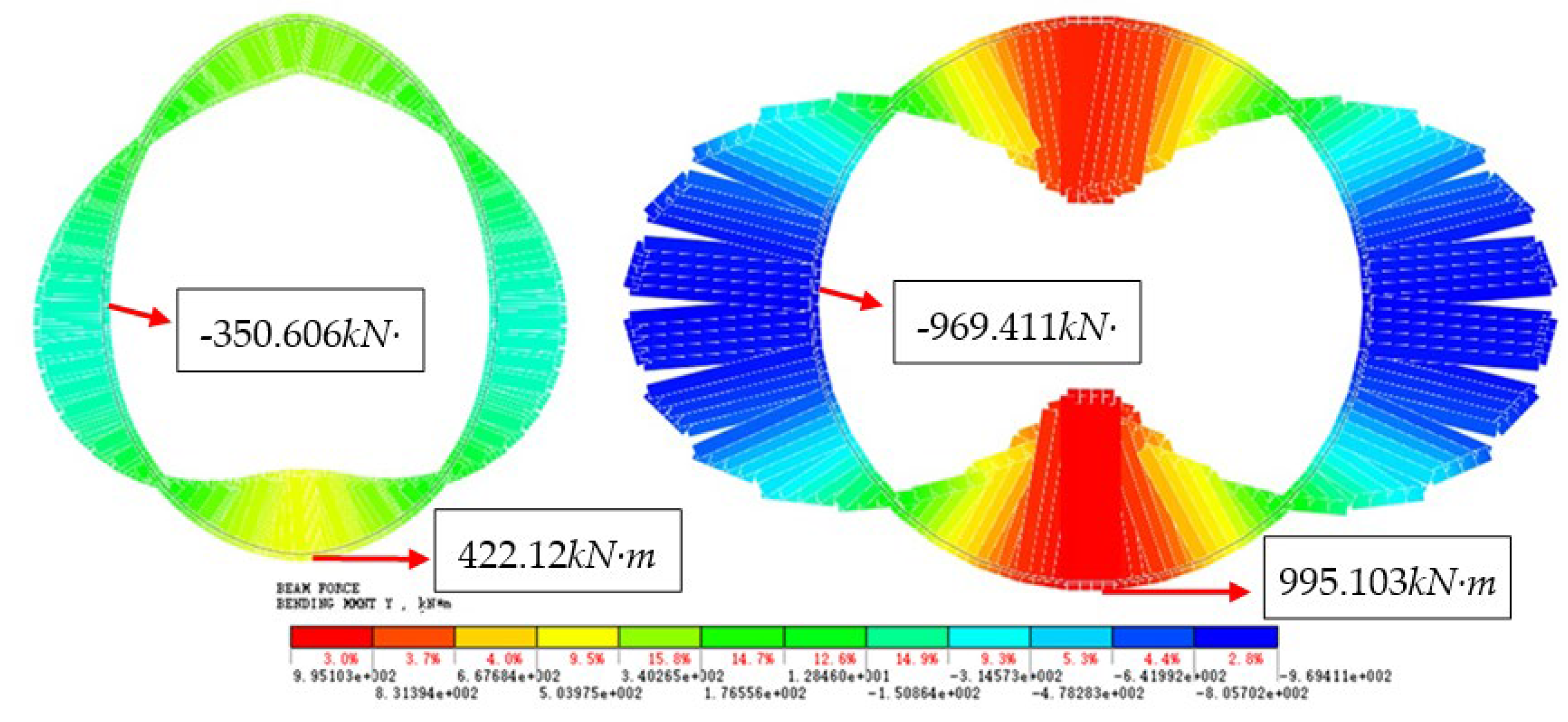
| Engineering Conditions | H/m | Minimum Bending Moment Shield Tunnel Cross-Section | Circular Shield Tunnel Cross-Section | ||
|---|---|---|---|---|---|
| Max Bending Moment/kN·m | Min Bending Moment/kN·m | Max Bending Moment/kN·m | Min Bending Moment/kN·m | ||
| 1 | 7 | 218.644 | −164.328 | 362.403 | −327.64 |
| 2 | 13 | 245.091 | −208.737 | 567.907 | −538.893 |
| 3 | 19 | 331.966 | −275.233 | 779.613 | −755.177 |
| 4 | 25 | 422.12 | −350.606 | 995.103 | −969.411 |
Publisher’s Note: MDPI stays neutral with regard to jurisdictional claims in published maps and institutional affiliations. |
© 2022 by the authors. Licensee MDPI, Basel, Switzerland. This article is an open access article distributed under the terms and conditions of the Creative Commons Attribution (CC BY) license (https://creativecommons.org/licenses/by/4.0/).
Share and Cite
Huang, D.; Jiang, H.; Xu, C.; Tu, W.; Li, X.; Wang, W. A New Design Method of Shield Tunnel Based on the Concept of Minimum Bending Moment. Appl. Sci. 2022, 12, 1082. https://doi.org/10.3390/app12031082
Huang D, Jiang H, Xu C, Tu W, Li X, Wang W. A New Design Method of Shield Tunnel Based on the Concept of Minimum Bending Moment. Applied Sciences. 2022; 12(3):1082. https://doi.org/10.3390/app12031082
Chicago/Turabian StyleHuang, Dawei, Hao Jiang, Changjie Xu, Wenbo Tu, Xue Li, and Wei Wang. 2022. "A New Design Method of Shield Tunnel Based on the Concept of Minimum Bending Moment" Applied Sciences 12, no. 3: 1082. https://doi.org/10.3390/app12031082
APA StyleHuang, D., Jiang, H., Xu, C., Tu, W., Li, X., & Wang, W. (2022). A New Design Method of Shield Tunnel Based on the Concept of Minimum Bending Moment. Applied Sciences, 12(3), 1082. https://doi.org/10.3390/app12031082