Article

Designed Circularly Polarized Two-Port Microstrip MIMO Antenna for WLAN Applications

1
School of Electronics and Information Engineering, Harbin Institute of Technology, Harbin 150001, China
2
College of Internet of Things (IoT) Engineering, Changzhou Campus, Hohai University (HHU), Changzhou 213022, China
3
College of Computer Science and Technology, Nanjing University of Aeronautics and Astronautics (NUAA), Nanjing 211106, China
4
School of Electronics and Information Engineering, Nanjing University of Aeronautics and Astronautics (NUAA), Nanjing 211106, China
*
Author to whom correspondence should be addressed.
Appl. Sci. 2022, 12(3), 1068; https://doi.org/10.3390/app12031068
Submission received: 22 November 2021 / Revised: 9 January 2022 / Accepted: 18 January 2022 / Published: 20 January 2022

Abstract

:
The proposed work describes a corner square-cut square-patch multiple-input multiple-output (MIMO) antenna with reduced mutual coupling for circular polarization (CP). A two-port MIMO-CP antenna was designed and operated at 5.6 GHz for wireless local area network (WLAN) applications. The dimensions of the MIMO-CP antenna were 22.5 × 50 mm 2 ( 0.43 λ 0 × 0.933 λ 0 ) and the FR4 substrate height was 1.6 mm. Between the two-elements, the edge-to-edge distance was 12.2 mm (0.227 λ 0 ), where λ 0 was the free space wavelength at 5.6 GHz. A slot was created in the middle of the ground in the proposed MIMO antenna to reduce mutual coupling and improve CP. The ground slot improves impedance matching and provides a better S-parameter and axial ratio (AR), according to the antenna results. According to the simulated results, the proposed antenna bandwidth of 5.23–6.42 GHz (21.4%) for S11 were < 10 dB, isolation was −37 dB with a peak gain of 6 dB and AR 3 dB from 5.37 to 5.72 GHz (6.25%). The proposed antennas are simple to fabricate, have low profiles, are inexpensive, have good isolation, and are CP. The diversity gain (DG) and envelop correlation coefficient (ECC) results are better in the simulated frequency band. A MIMO-CP antenna geometry prototype is built and measured for comparison, yielding good results when compared to the simulated and measured results. The MIMO-CP antenna, as designed, is suitable for WLAN applications.

1. Introduction

In current communication systems, multiple-input multiple-output (MIMO) antennas are used to send and receive multiple data signals over the same radio channel [1]. MIMO antennas are important components in current wireless communication systems as they can reduce interference, and enhance connection quality and channel capacity without requiring more bandwidth. Electromagnetic wave interactions between near elements, which impact antenna parameters, such as bandwidth and radiation pattern, are a major challenge in MIMO antenna design [2,3]. There are multiple antennas in base stations and devices. A sufficient distance between nearby patches is required to reduce mutual coupling [4]. To solve this problem, several methods have been explored to reduce mutual coupling, such as an electromagnetic band gap (EBG) structure [5,6,7], defected ground structure (DGS) [8,9], neutralization lines [10], stub loading technique [11], slots [12], meta-material [13], and resonator structures [14]. A wide-band two-port circularly polarized MIMO printed antenna is obtained by designing the ground plane and employing asymmetric Z-shaped radiating patches to improve isolation [15].
To attain good MIMO properties, these approaches are frequently coupled. Antennas are used in a variety of wireless communications applications, including the short-range wireless local area network (WLAN) application [16]. WLAN MIMO systems are of interest to scientists that use them to increase wireless communications between electronic devices (such as PCs, laptops, and smartphones) [17]. WLAN systems use base stations or access points to deliver connectivity to wireless devices [18,19]. In [20], the authors present a design of a leaky-wave antenna (LWA) array capable of generating six simultaneously-scanned directive beams when connected to a MU MIMO 802.11ax base station Router WiFi for indoor smart wireless access point applications. In [21], the authors proposed a new full-rate coding scheme for MIMO-OFDM systems operating over slow-fading wireless channels. The scheme consisted of a block code sent over transmit antennas, OFDM tones, and radiation states of reconfigurable antennas. The transmit or receive antenna radiation patterns can be dynamically changed to improve system performance in a dynamic radiation pattern diversity (DRPD) MIMO system [22].
Several MIMO antenna systems for WLAN applications have been presented in recent years, with much of the research focusing on ways to reduce the mutual coupling result and to attain high isolation among antenna units because lesser dimensions and areas are limited when organizing antennas. However, some MIMO antennas are designed for the WLAN band (2.4/5.8 GHz) [23,24,25,26]. Polarization and pattern diversity, on the other hand, appear to be promising techniques for decreasing the correlation between antenna far-fields without increasing the circuit dimension. Reduced signal attenuation, multi-path fading, and absorption losses are advantages of circularly polarized (CP) antennas [27,28]. When compared to LP antennas, the CP MIMO antenna, extends wireless coverage, minimizes the polarization mismatch effect, and distributes power uniformly between feed points [29]. In terms of improving diversity gain (DG) or channel capacity (CC), CP antennas have been investigated as viable candidates for MIMO applications.
Truncated corner metallic radiators are used along with periodic parasitic elements to make the CP MIMO antenna, to improve the isolation and axial ratio [30]. The antenna was designed with truncated corner square patches, and the parasitic element technique was also used for BW enhancement. The MIMO antenna in [31] was formed by two diagonally slotted square patches and four parasitic elements for performance improvement. The MIMO antenna attained good isolation of more than 18 dB while fitting on a board measuring 30 × 30 × 1.6 mm. Two ground radiation antennas with polarization diversity performance for WLAN applications in wearable devices have been proposed in [32]. In [33], the authors proposed a circularly polarized MIMO antenna based on an L-shaped dielectric resonator (DR) for WLAN applications. A compact and planar CP-MIMO patch antenna with diversity polarization was described in [34]. The antenna achieved good impedance matching, high isolation, and better gain, but its dimensions are large and the axial ratio (AR) bandwidth was narrow. In [35], the authors show how to use metamaterial to reduce mutual coupling among microstrip patch antennas in a MIMO antenna for WLAN band, which still have limited bandwidth, and the gain is just 4 dB. In [36], the authors designed a four-element compact MIMO antenna for WLAN band with simultaneous pattern and polarization diversities, but there was only 15.4 dB of isolation. In [37], a quad-port MIMO antenna was based on a miniaturized slit-loaded modified slot antenna for the 5 GHz band of WLAN.
In [23], the authors proposed a three-element compact MIMO antenna designed with polarization (linear/circular) diversity. For 5.8 GHz WLAN values, [38] designed a CP-MIMO antenna with a power divider, which uses two tuned 90-degree slots. The impact of design on S-parameters and AR was explored in this paper for many features of the MIMO antenna. In [39], for point-to-point communication, a CP-MIMO array antenna in WLAN applications was introduced. In [40], a DR two-port MIMO antenna (DRA) with a circularly polarized radiation was proposed, but having low isolation, the gain was 3.8, and a large dimension. In [41], a compact size and high isolation 2 × 2 , a MIMO antenna was used for various applications of the ISM band, WLAN, of the lower frequency band of 5G. In [42], a wideband CP two-port MIMO antenna with a compact size was designed for the fifth-generation (5G) region in the sub-six GHz band. A wideband CP-MIMO antenna line patch was proposed among two antenna elements in [43]. A two-port CP-MIMO antenna was designed to have simultaneous patterns and diversity polarization for the WLAN application band [44]. For WiMAX applications, a dual-port MIMO antenna system with circular polarization diversity was investigated [45]. In [46], the MIMO system had a strong pattern and polarization diversity, but it did not have isolation and gain. A DGS structure was used in [47] to improve the inter-port isolation of a super compact 2 × 2 MIMO antenna.
In this paper, a simple corner square-cut square-patch MIMO-CP antenna is presented for the WLAN application. The design consists of a two-corner square-cut square-shaped patch antenna and a slot in the middle of the ground, which gives low mutual coupling and CP. In this work, first, we designed a single square-cut patch antenna CP for the WLAN application. Then, for the same frequency MIMO-CP antenna with the ground slot, given a similar bandwidth, increase the return loss (S11) value from −21 to −38 dB, shift resonant frequency from 5.53 to 5.6 GHz, reduce mutual coupling, and improve axial ratio. The edge-to-edge distance d ( 0.227 λ 0 ) is fixed between two elements for better performance of the MIMO-CP antenna. The analysis of the proposed MIMO-CP antenna was simulated using computer simulation technology (CST) Microwave Studio, and it was fabricated on an FR-4 low-cost dielectric substrate with relative permittivity of 4.4, loss tangent of 0.02, thickness of 1.6 mm, and a total area of 22.5 × 50 mm2. The fabricated MIMO-CP antenna prototype and measurement results are presented in Section 5.
The main contributions of this work compared to the recent literature are detailed below:
A comparative study is carried out to explain the novelty of the proposed MIMO-CP antenna. The comparison clearly shows that the designed antenna gives better performance than the other designs, in terms of size, bandwidth, axial ratio, gain, and isolation. It is shown that the designs in [35,36,37,42,44,46] have small sizes, but low isolations, low gains, and narrow bandwidths, while our proposed antenna has the lowest profile and smallest lateral dimensions to achieve good performance. The designs in references [33,38,40,45] suffer from bigger sizes, low isolations, low gains, narrow bandwidths, and the axial ratios are compared to the proposed designs. Furthermore, the designs in [41,47] are complicated structures, larger sizes, and have lower isolations, gains, and narrow bandwidths. The suggested MIMO antenna is well-suited for various wireless applications due to its low profile, high peak gain, low envelope correlation coefficient (ECC), high diversity gain, good isolation, large bandwidth, and axial ratio.
The rest of the paper is organized as follows: Section 2 presents the theory and design while Section 3 presents the MIMO antenna CP results. Moreover, the parametric study is presented in Section 4 whereas the result and discussion of MIMO-CP are presented in Section 5. Section 6 presents the MIMO antenna system parameter and, finally, the paper is concluded in Section 7.

2. Theory and Design

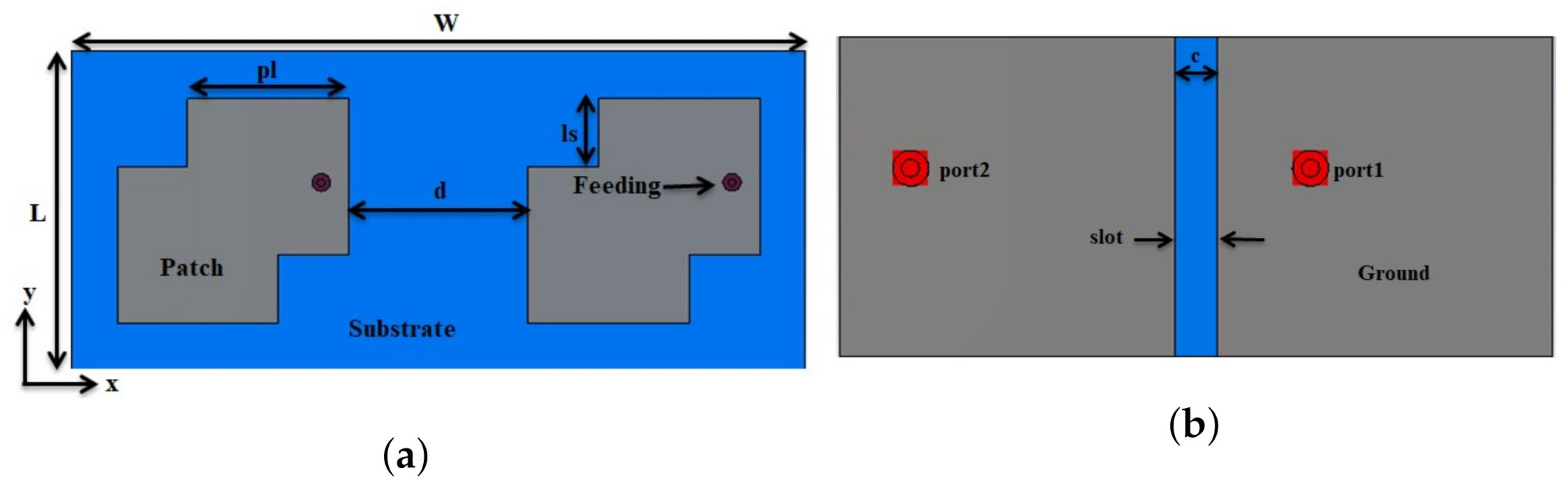
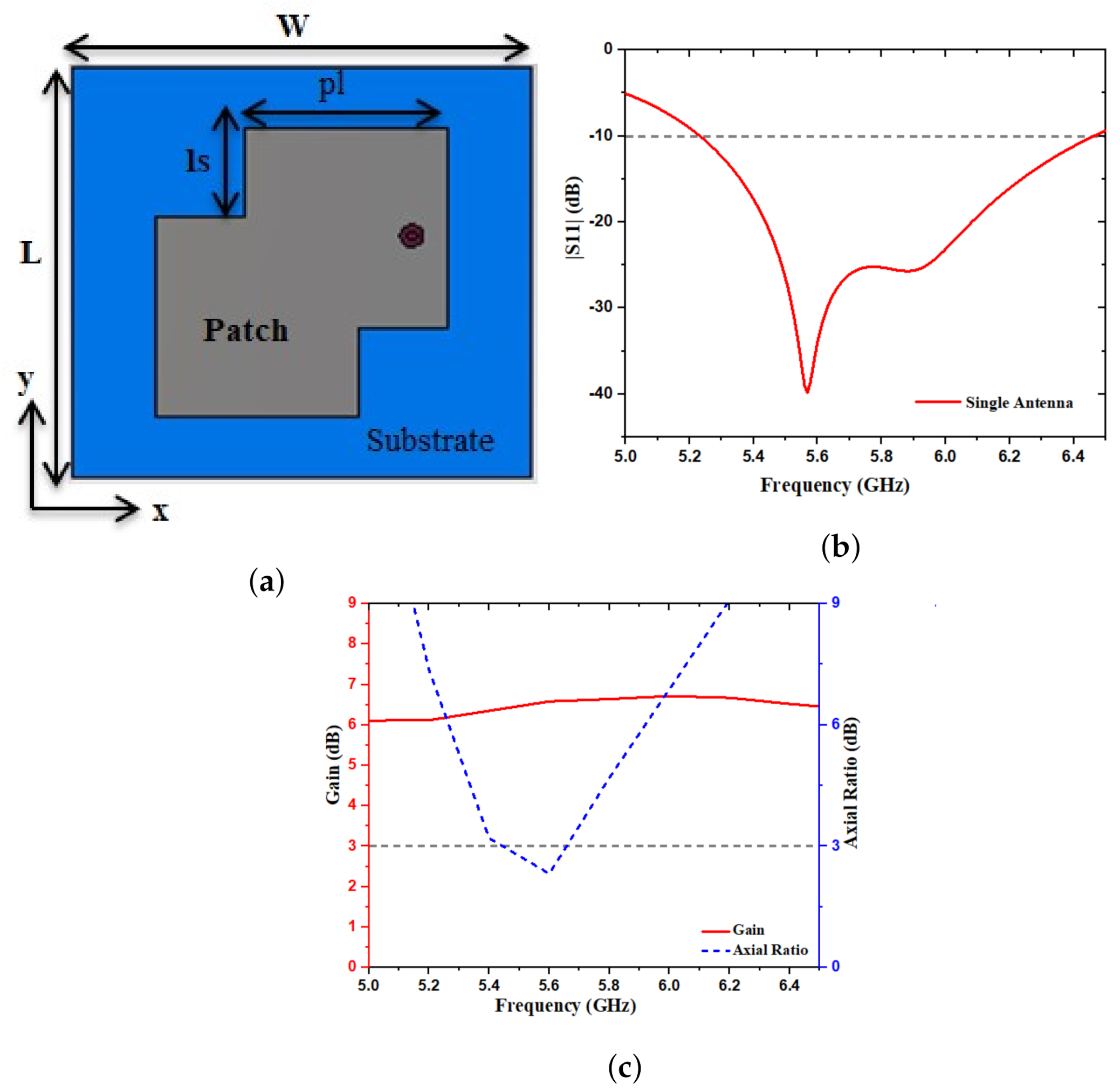
2.1. Single Antenna Design

First, the designed single antenna is given in Figure 1a. The single antenna structure was implemented on a thick FR4 substrate ( ε r = 4.3 , tan δ = 0.025 and height of substrate h = 1.6 ) with outer dimensions of L × W = 22.5 × 25 mm 2 , whereas L and W represent the length and width of the single antenna. The ground plane and the substrate are separated by an air gap height, ha = 3.5 mm. The rectangular ground plane was created according to that same dimension of the substrate. A 50 Ω coaxial probe feeds the antenna via an SMA connector, with the outer part connected to the ground and the inner part connected to the patch.
A square-shaped patch with a square-cut at the corner dimension of the width and length ( l s × l s ) was introduced for CP. Since the square patch gives a linear polarization, the corners of the patch were cut to become CP. The single antenna was designed for the WLAN application. The reflection coefficient S 11 of the simulated single antenna design operates at around 5.55 GHz, as shown in Figure 1b. According to the results of our single antenna simulation, the impedance bandwidth of < 10 dB is sufficient to cover the WLAN application. The AR and gain of the single antenna with an operating frequency band are given in Figure 1c. The simulated 3 dB AR ranges from 5.44 to 5.65 GHz. CST software was used to simulate the antenna. The proposed single antenna parameters are: W = 24.5 mm , L = 22.5 mm , w l = 11 mm , l s = 4.8 mm , h a = 3.5 mm , h = 1.6 mm .

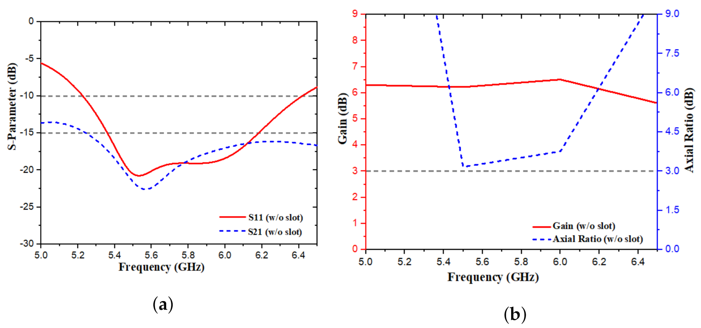
2.2. MIMO-CP Antenna Design

Figure 2 shows the proposed MIMO-CP antenna designed structure. Two single antennas were used to design the MIMO-CP antenna for WLAN applications. The two-corner, square-cut, square-shaped patch antenna is printed on the top side of the thick FR4 substrate. The FR4 substrate was not grounded and the air gap, ha, was inserted between the ground plane and the substrate. The height of the FR4 substrate (thickness = 1.6 mm, relative permittivity = 4.3 and tangent loss = 0.025). The length and width of the proposed MIMO antenna were 22.5 × 50 mm. The antenna was excited with a 50 Ω coaxial cable, whose inner and outer parts were connected with the ground and patch. The edge-to-edge distance between the two MIMO antennas was 0.227 λ 0 . The CST microwave studio was used to simulate the antenna. The following sections present the design steps.
Figure 2 gives the front and back views of a MIMO antenna. The geometry of the substrate was rectangular with a side length and width of ( L × W ) . The gap between the ground and the patches was tuned to achieve the required impedance bandwidth and was kept at h a = 3.5 mm . The radiating elements consisted of two square patches in which a square-cut at the corner was used for CP. The length and width of the square-cut were ( l s × l s ) . For the best MIMO antenna results, the edge-to-edge distance between the two patches was kept at d = 12.2 mm . The suggested antenna was designed with less return loss, high isolation (low mutual coupling), AR, and enough antenna gain, within the desired bandwidth impedance bandwidth. Various parameters of the MIMO antenna are shown in Table 1.

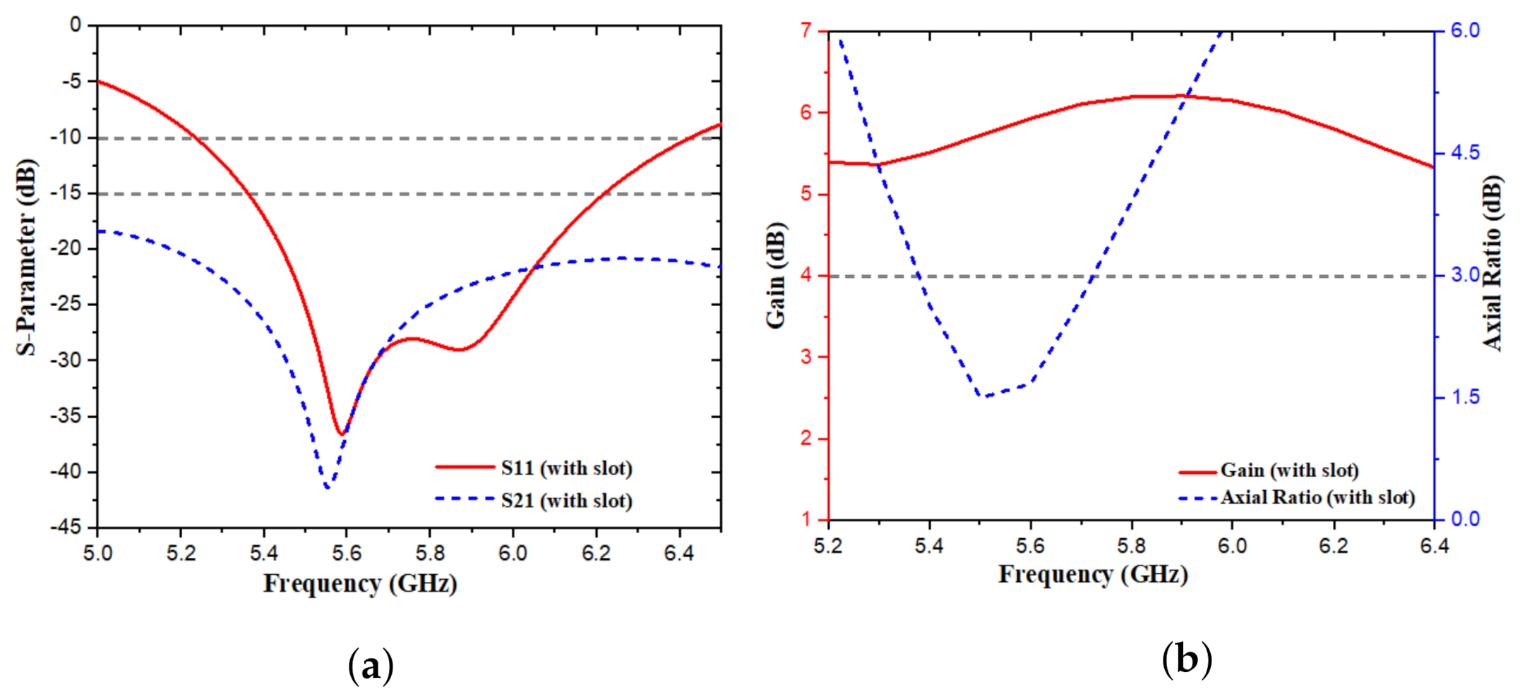
3. MIMO Antenna Circular Polarization Results
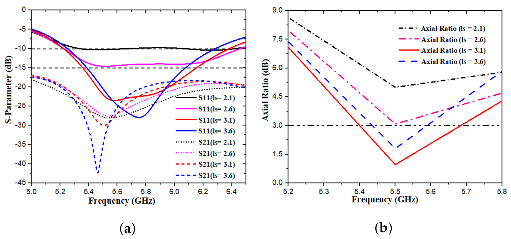
From a single antenna, a square-shaped patch with a square-cut at the corners obtains a circular polarization. Later, the single antenna combines to make a MIMO-CP antenna, which has good S11, but bad S21, and an axial ratio. To improve the isolation and axial ratio, the slot is produce in the ground. The design combines both conventional techniques (square-shaped patch with a square-cut at the corners and ground slot) to shift the resonance frequency, improve AR, as well as isolation. In fact, the ground slot, having a width and length of the slot (c = 1.5 mm and g = 11.25), provides a longer effective path for the current flow, efficiently. The dual elements inspired by the ports are denoted as port-1 and port-2. The MIMO antenna was designed in two steps—a MIMO-CP antenna with no ground slot and a MIMO-CP antenna with the ground slot. First, we designed the antenna without the slot for the desired frequency. The proposed MIMO antenna with no slot in the ground shows a −10 dB impedance band of 5.22–6.41 GHz, with more than 20 dB of return loss, and resonates at a 5.53 GHz frequency with 22 dB of isolation at resonant, as shown in Figure 3a. From Figure 3b, the antenna without a slot in the ground has an AR value greater than 3 dB, indicating that it is no longer in CP polarization. On the other hand, the proposed MIMO antenna with a slot shows a −10 dB impedance band of 5.23–6.42 GHz, with more than a 38 dB return loss, as shown in Figure 4a. In this case, the antenna resonates at 5.6 GHz frequency with 37 dB of isolation and an AR value of 1.51 dB, and a 3 dB AR band of 5.37–5.72 GHz. The AR is used to identify the feature of CP elements. The CP frequency ranges are from 5.37–5.72 GHz; the 3-dB AR bandwidth is 6.25%, as shown in Figure 4b. The proposed MIMO-CP antenna covers the WLAN application. The proposed antenna peak gain is 6 dB at a resonant frequency.
Surface current distribution explains the performance analysis of isolating the structure over the desired frequency band. Figure 5a,b gives the MIMO-CP surface current distribution with and without a ground slot at resonant frequency achieved by exciting antenna 1 and terminating antenna 2 by the matched load, respectively. When the two patches are arranged on a ground with no slots, on the right side of the coupled antenna element, a high current is induced, while on the left side, a small current is produced when the left side antenna is excited. Figure 5a shows that without using of ground slot, some of the surface currents are coupled from antenna 1 to antenna 2. The proposed ground slot reduces the high mutual coupling between the antenna parts, which explains why mutual coupling occurs. In the case of a MIMO-CP antenna with a ground slot, the currents are especially focused at the corners of the right-side patch and there is no current on the left-side patch, as shown in Figure 5b. The magnetic field is trapped within the ground slot as a result of these phenomena, preventing the surface current from flowing further. As a result of using a slot, electromagnetic energy is prevented from propagating from antenna 1 to antenna 2, resulting in a high level of isolation. Finally, Figure 6 presents the current distributions that are used to determine the proposed antenna’s CP generation. The simulated surface current, with a different port excitation at 5.6 GHz is taken for clarification. Figure 6a,b shows the antenna at 5.6 GHz; the current is strongly spread on the patch in which the vector rotates in a counter-clockwise direction when the phase changed from 0 to 90 . Thus, the MIMO antenna for port-1 excitation was able to RHCP broadside direction. Figure 6c,d shows when port-2 was excited. However, in this case, the vector rotated in a clockwise direction when the phase changed.

4. Parametric Study

The parametric analysis of the MIMO-CP antenna is presented using different values from the geometry, which selected the best value for a better performance. The parametric study was done by the corner cut length and width (ls) and the distance (d) between the two patches. The corner cut at the patch improves the impedance matching of S11, mutual coupling, and AR. The distance between the patches further improves the results within the frequency band.

4.1. Changing Length and Width (ls) of the Patch Corner Cut

The MIMO-CP antenna, simulated for different widths and lengths of the corner cut, to effect the S-parameters and axial ratio, are presented in Figure 7. The length and width of the corner cut varies from 2.1 to 3.6 mm. When the ls increased from 3.1 mm, the resonance frequency shifted from a lower to a higher frequency, and obtained poor impedance matching between S11 resonance frequency and S21, as shown in Figure 7a; while, axial ratio decreased. By decreasing the ls from 3.1 mm, the reflection coefficient decreased, the isolation decreased, and there was poor axial ratio. Hence, ls are fixed to c = 3.1 to improve the impedance bandwidth of the S11 resonance frequency at 5.58 GHz; S21 at the same frequency is −27 dB, and improves axial ratio.

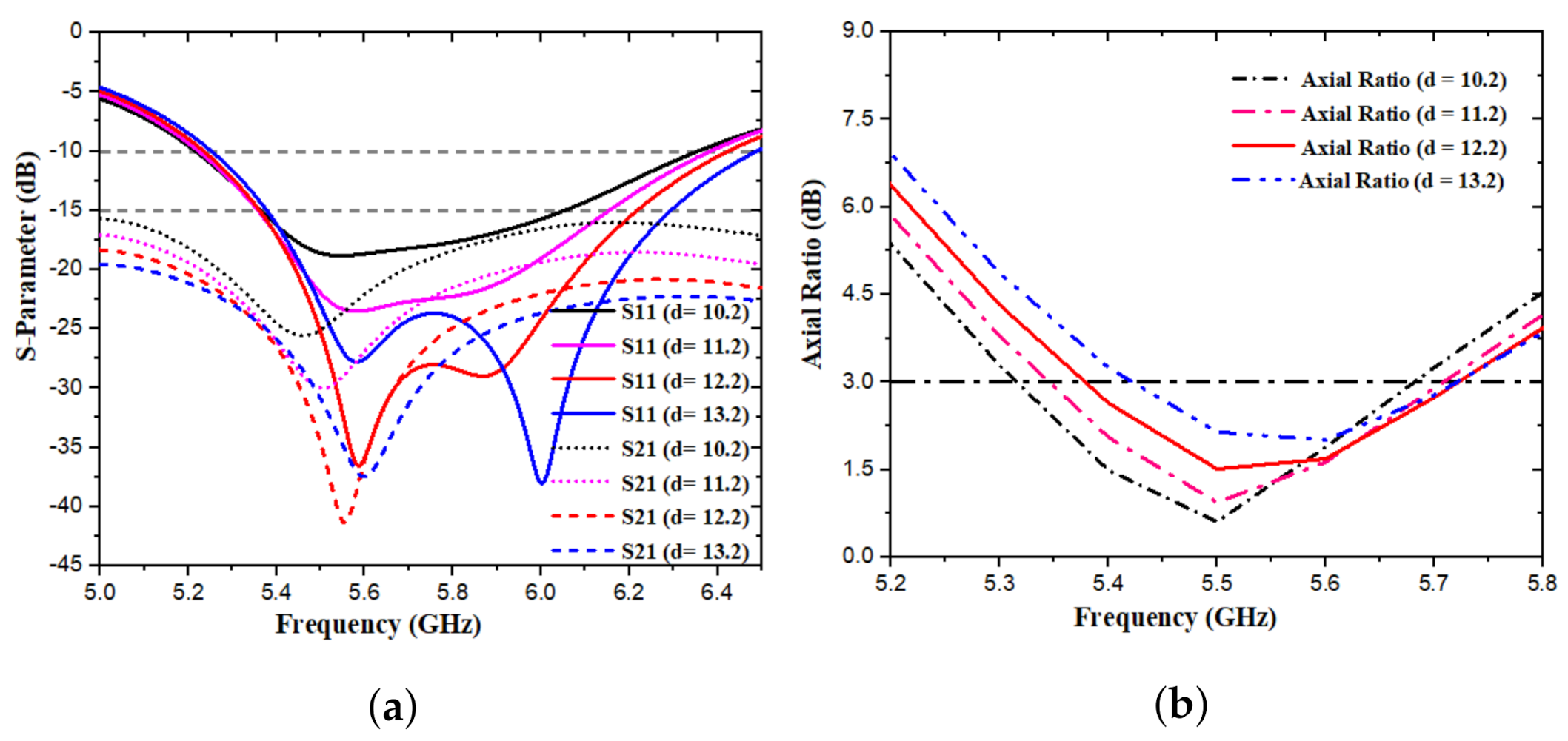
4.2. Changing the Distance (d) between the Patches

The length and width of the patch corner cut are fixed at l s = 3.1 mm, and changes the edge-to-edge distance (d) between the two elements. The distance (d) varied from 10.2 to 13.2 mm between the patches. The antenna-simulated results are presented in Figure 8. The simulated results show that, when increasing the distance from 12.2 mm, the resonance frequency shift from 5.58 GHz to a high frequency 6.1 GHz and poor impedance matching between S11 and S21 also decrease the axial ratio. When the distance is reduced from 12.2 mm, the reflection coefficient S11 decreases, as does the isolation, as shown in Figure 8a. While, an increased axial ratio is presented in Figure 8b. The S11 and S21 frequency bands for various distances of d are shown in Figure 8a. It is clear that, when d was 12.2 mm, the S11 frequency band ranged from 5.23 to 6.42 GHz, resonating at 5.6 GHz. However, the remaining plots were also in the range of <10 dB. The distance (d) was fixed to 1.2 mm to achieve high isolation and improve the remaining results of the MIMO antenna within the frequency band. The performance was considerably better when the edge-to-edge distance (d) between the two elements and the length and width of the square-cut ls were fixed at l s = 3.1 and d = 12.2 for better performance. Furthermore, the isolation improves; S11 and S21 are matched at the center frequency.

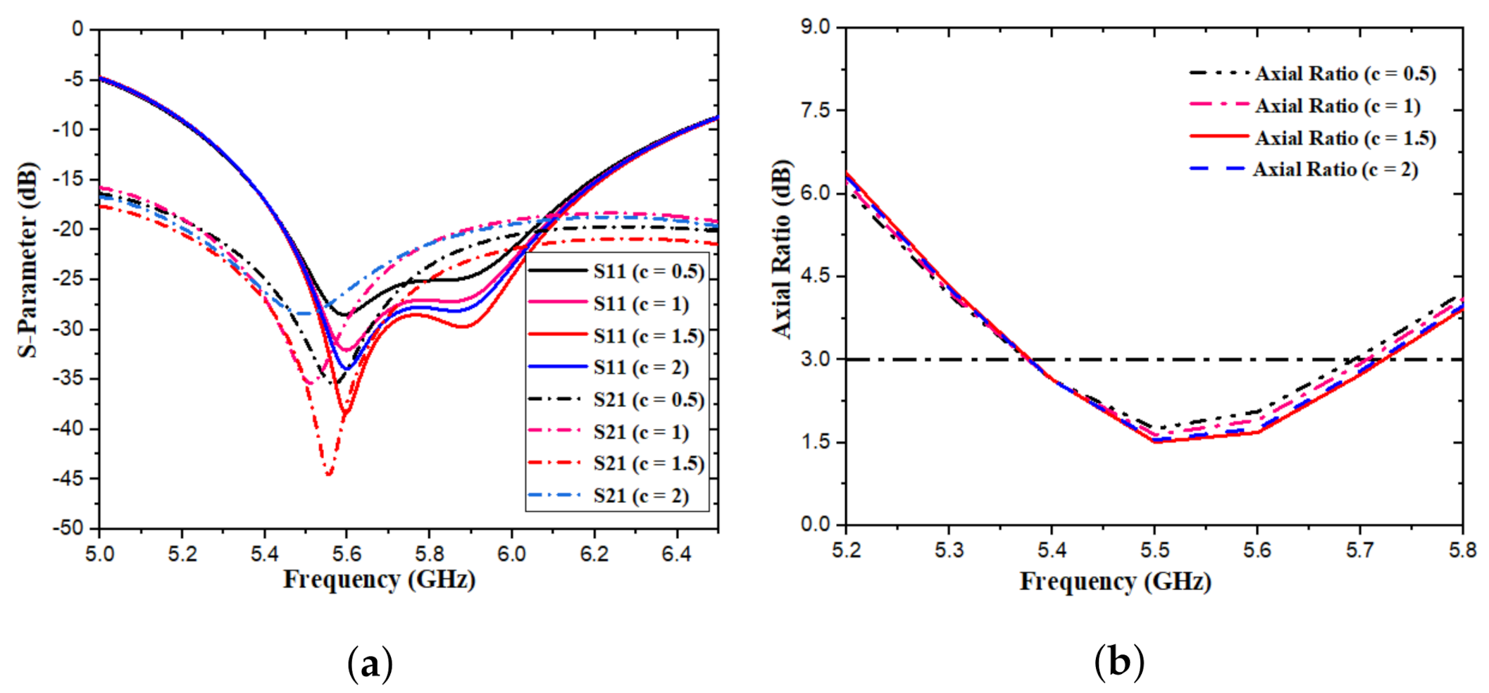
4.3. Changing the Width of the Ground Slot (c)

Figure 9 shows the reflection coefficients and axial ratio for the proposed antennas with different slot widths c. The MIMO-CP antenna slot widths vary from 0.5 to 2 mm. It is clear from the figure that this is when the width of the slot decreases or increases from 1.5 mm, affecting impedance matching of the S-parameter, with relatively less effects on the axial ratio. An optimum value of c is found to be 1.5 mm. Thus, the width of the slot is fixed to c = 1.5 mm, to improve impedance matching of the S-parameter and have a better axial ratio.

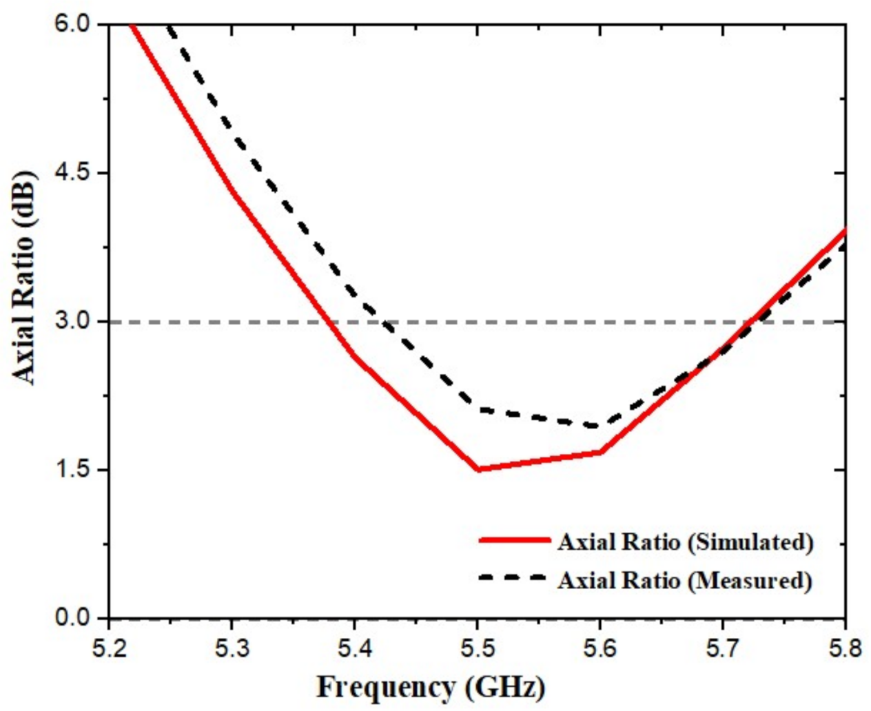
5. Results and Discussion of MIMO-CP

The simulation results were generated using CST Microwave Studio software. The proposed MIMO-CP antennas fabricated are shown in Figure 10. In the following paragraphs, the simulated and experimental results of MIMO-CP are explained.
The fabricated antenna, S-parameter, was tested by using a PNA performance network analyzer. Simulated and measured S-parameter results of the antenna are given in Figure 11. The simulated and measure results were almost matching, but some mismatches were observed, possibly due to the effect of the SMA connector). The simulated and measured results show good agreement within the frequency band. Figure 12 presents the simulated and measured AR results comparison. The AR of the proposed radiator is in the broadside direction; however, the proposed antenna measurement and simulation results of CP remain below 3 dB AR within the antenna bandwidth.
Figure 13a shows the simulated and measured gains of the proposed MIMO-CP antenna. The antenna peak gain is obtained at 5.6 GHz around 6 dB, which is suitable for practical applications. Efficiency is also the important parameter of the antenna, as shown in Figure 13b. In the operating bandwidth, the simulated radiation efficiency of the proposed MIMO-CP antenna is greater than 80%. The efficiency of the experimental antenna is measured in an anechoic chamber. It can be seen that the measured and simulated S-parameters are in good agreement; however, there are some discrepancies among experimental and simulated S-parameters (this is due to manufacturing tolerances and variations in the characteristics of the material used).
The suggested simulated and measured antenna 2D far-field radiation patterns are shown in Figure 14, on two main planes—E-plane and H-plane, respectively—at a central frequency. The impact of the resonators on the antenna radiation patterns was investigated using simulation and measurement results for H-plane and E-plane far-field radiation patterns for the two fabricated MIMO-CP antennas. Figure 14 shows the radiation patterns that occur when port-1 is excited and port-2 is terminated by a matched load. Both the E-plane and H-plane radiation patterns are directional. The 2D left-hand CP (LHCP) and right-hand CP (RHCP) radiation patterns for port-1 at 5.6 GHz are shown in Figure 15. When port-1 is excited, the RHCP field component is stronger than the LHCP component in the broadside direction. The proposed antenna is right-handed circularly polarized, because the RHCP pattern is “more than”—as compared to LHCP—at both the E-field and H-field.

6. MIMO Antenna System Parameters

In this section, the presentation of the suggested MIMO-CP antenna is calculated by some essential parameters, which characterize MIMO antenna systems, such as DG and ECC. These parameters are illustrated in detail in this section.

6.1. Envelope Correlation Coefficient

The proposed antenna diversity presentation is analyzed in terms of ECC, to ensure good MIMO performance. Isolation and correlation of communication channels can be observed from envelope correlation coefficient (ECC) value. ECC can be derived from the radiation pattern of all the antennas in a multi-antenna system that shows how much the radiation pattern of each antenna affects the radiation pattern of other antenna. Having a low ECC is very important for the “robustness” of the proposed MIMO antenna [48]. The radiation pattern can be used to calculate it for a two-port MIMO antenna, as shown in Equation (1) [49].
ρ e = 4 π [ F 1 ( θ , ϕ ) × F 2 ( θ , ϕ ) d Ω ] 2 4 π [ F 1 ( θ , ϕ ) ] 2 d Ω 4 π [ F 2 ( θ , ϕ ) ] 2 d Ω
The ECC ( ρ e ) is computed from the far-field radiation pattern, as in Equation (1). Where F 1 ( θ , ϕ ) is the MIMO array far field property when port-1 is excited. The solid angle is denoted by Ω . From Figure 16a, given a simulated and measured ECC of less than 0.001 at over the entire frequency range, it shows a low correlation between the two antennas. For a better MIMO antenna, ECC should have less than 0.5 [50].

6.2. Diversity Gain

When transmitters receive multiple forms of the transmission stream through distinct channel pathways, the effects of diversity are frequently accomplished. The diversity gain value was found to be near 10 dB, indicating good diversity performance. The value of diversity gain can be computed using Equation (2) from the envelope correlation coefficient [51].
D G = 10 × 1 ( E C C ) 2
where ECC denotes the envelope correlation coefficient, and DG denotes diversity gain. Figure 16b shows the proposed antenna’s simulated and measured diversity gain, which is close to 10 dB.
The characteristics of the MIMO-CP antenna are compared with those of other state-of-the-art antennas, regarding mutual coupling reduction and circular polarization, as shown in Table 2. The objective of the current work is to improve axial-ratio and reduce mutual coupling, as well as high gain using MIMO-CP antenna. As observed from the comparison, the proposed design is a two-port MIMO-CP antenna. Apart from Table 2, a pair of complementary point symmetric micro-machined meander line (ML) slots was inserted on the ground plane between two patches that are closely spaced, to suppress mutual coupling without any resonant frequency mismatch between S11 and S22 [52]. In [34], for high isolation, F-shaped DGS were used with simple offset feeding for circular polarization, but the design suffers from a narrow axial ratio and a complicated structure. In [53], for improved isolation, defected ground slits were etched between two radiators with the lowest bandwidth and axial ratio. In [54], in the ground, an inverted Z-shaped slot was etched to produce circular polarization for both the axial ratio and mutual coupling. In [33], the authors presented the design of the L-shaped CP MIMO antenna, using DGS for the WLAN application. However, in order to achieve circular polarization characteristics, they used two complicated slots in the ground, making the design comparatively more complex and requiring a large antenna size.
This work is unique in two ways. First, we determined how geometrical parameters (main square patch heights, corner square-cut, and length/width) affect MIMO-CP antenna characteristics and how these can be adjusted to achieve an optimal design without requiring extensive simulations. Second, the final design incorporates a slot in the ground that improves both the isolation and axial ratio. In addition, an air gap was provided between the ground and the substrate to eliminate dielectric losses, resulting in maximum antenna gain and efficiency.
To the best of the authors’ knowledge, this paper is the first to implement an antenna with MIMO-CP circular polarization by implementing a square-cut at the corner of a square patch antenna. Our antenna has several advantages over previously published CP antennas. Circular polarization is typically obtained when such an antenna structure is excited with two orthogonal transverse modes of equal amplitudes, but 90 degrees out of phase. Another traditional method is to use patches that are cut at two opposite corners of the radiating patch. Here, we simulated a square-cut at the corner of the MS antenna. As stated in the manuscript, many techniques include truncated corners, two corners of patches are truncated; stubs, slits, notches, and embedded slots for the CP antenna. We found that the advantages of our presented antenna are very different from those of the corner-truncated square patch antenna. To summarize, none of the designs combine the advantages of a simpler design, a high isolation high gain, broadband CP characteristics, and MIMO capabilities in one package, such as our proposed design. Moreover, our design is unique and simple because it is the only available MIMO-CP antenna that covers the WLAN band (5.23–6.42 GHz) applications.

7. Conclusions

In this paper, we designed a simple MIMO-CP antenna for the WLAN band. The MIMO-CP antenna has an easy structure with dimensions of 22.5 mm × 50 mm , and it operates at 5.6 GHz. To achieve CP, the simple square patch was cut at the corner using the concept of CP. Improving impedance matching, high isolation, and better AR can be archived using a simple technique that produces a slot in the ground. The antenna impedance bandwidth ranged from 5.23 to 6.42 GHz and A R 3 dB from 5.37 to 5.72 GHz, with better isolation | S 21 | 37 dB within the S11 frequency range. At the resonant frequency, peak gain and radiation efficiency were 6 dB and 84%, respectively. The ECC was 0.001 and DG was nearly 10 dB lower. The designed MIMO-CP antenna results (simulated and measured) are suitable for WLAN applications.

Author Contributions

Conceptualization, I.K. and I.U.; methodology, I.K.; software, I.K.; validation, I.K., S.U.R. and K.Z.; formal analysis, K.Z.; investigation, I.K.; resources, K.Z.; data curation, I.K.; writing-original draft preparation, I.K. and I.U.; writing-review and editing, K.Z. and H.U.; visualization, Q.W.; supervision, K.Z.; project administration, K.Z. and Q.W.; funding acquisition, K.Z. All authors have read and agreed to the published version of the manuscript.

Funding

This research was funded by National Science Foundation of China, grant number 62171165.

Institutional Review Board Statement

Not applicable.

Informed Consent Statement

Not applicable.

Data Availability Statement

The data that support the findings of this study are available from the corresponding author upon reasonable request.

Acknowledgments

The authors acknowledge the support from the Natural Science Foundation of Heilongjiang Province under grant no. YQ2020F002, and the open project of the Guangxi Key Laboratory of Wireless Wideband Communication and Signal Processing.

Conflicts of Interest

The authors declare no conflict of interest.

References

  1. Kharche, S.; Reddy, G.S.; Gupta, R.K.; Mukherjee, J. Wide band circularly polarised diversity antenna for satellite and mobile communication. IET Microwaves Antennas Propag. 2017, 11, 1861–1867. [Google Scholar] [CrossRef]
  2. Nouri, M.; Aghdam, S.A. Reconfigurable UWB antenna with electrically control for triple on-demand rejection bandwidth. Microw. Opt. Technol. Lett. 2015, 57, 1894–1897. [Google Scholar] [CrossRef]
  3. Bait-Suwailam, M.M.; Siddiqui, O.F.; Ramahi, O.M. Mutual coupling reduction between microstrip patch antennas using slotted-complementary split-ring resonators. IEEE Antennas Wirel. Propag. Lett. 2010, 9, 876–878. [Google Scholar] [CrossRef]
  4. Ketzaki, D.A.; Yioultsis, T.V. Metamaterial-based design of planar compact MIMO monopoles. IEEE Trans. Antennas Propag. 2013, 61, 2758–2766. [Google Scholar] [CrossRef]
  5. Yang, F.; Rahmat-Samii, Y. Microstrip antennas integrated with electromagnetic band-gap (EBG) structures: A low mutual coupling design for array applications. IEEE Trans. Antennas Propag. 2003, 51, 2936–2946. [Google Scholar] [CrossRef] [Green Version]
  6. Kamal, M.M.; Ullah, I.; Ashraf, A.; Ullah, N. Designing band notch features in ultra-wideband antenna. In Proceedings of the 2017 7th IEEE International Symposium on Microwave, Antenna, Propagation, and EMC Technologies (MAPE), Xi’an, China, 24–27 October 2017; pp. 92–95. [Google Scholar]
  7. Rajo-Iglesias, E.; Quevedo-Teruel, O.; Inclan-Sanchez, L. Mutual coupling reduction in patch antenna arrays by using a planar EBG structure and a multilayer dielectric substrate. IEEE Trans. Antennas Propag. 2008, 56, 1648–1655. [Google Scholar] [CrossRef]
  8. Ibrahim, A.A.; Abdalla, M.A.; Abdel-Rahman, A.B.; Hamed, H.F. Compact MIMO antenna with optimized mutual coupling reduction using DGS. Int. J. Microw. Wirel. Technol. 2014, 6, 173–180. [Google Scholar] [CrossRef]
  9. Kamal, S.; Chaudhari, A. Printed Meander Line MIMO Antenna Integrated with Air Gap, DGS and RIS: Low mutual coupling design for LTE Applications. Prog. Electromagn. Res. C 2017, 71, 149–159. [Google Scholar] [CrossRef] [Green Version]
  10. Yang, Y.; Chu, Q.; Mao, C. Multiband MIMO antenna for GSM, DCS, and LTE indoor applications. IEEE Antennas Wirel. Propag. Lett. 2016, 15, 1573–1576. [Google Scholar] [CrossRef]
  11. Jabire, A.H.; Abdu, A.; Saminu, S.; Salisu, S.; Sadiq, A.M.; Jajere, A.M.; Ahmed, Y.K. Reduction of Mutual Coupling in UWB/MIMO Antenna Using Stub Loading Technique. Electr. Control. Commun. Eng. 2021, 17, 12–18. [Google Scholar] [CrossRef]
  12. OuYang, J.; Yang, F.; Wang, Z. Reducing mutual coupling of closely spaced microstrip MIMO antennas for WLAN application. IEEE Antennas Wirel. Propag. Lett. 2011, 10, 310–313. [Google Scholar] [CrossRef]
  13. Jabire, A.H.; Ghaffar, A.; Li, X.J.; Abdu, A.; Saminu, S.; Alibakhshikenari, M.; Falcone, F.; Limiti, E. Metamaterial Based Design of Compact UWB/MIMO Monopoles Antenna with Characteristic Mode Analysis. Appl. Sci. 2021, 11, 1542. [Google Scholar] [CrossRef]
  14. Mookiah, P.; Dandekar, K.R. Metamaterial-substrate antenna array for MIMO communication system. IEEE Trans. Antennas Propag. 2009, 57, 3283–3292. [Google Scholar] [CrossRef]
  15. Tiwari, R.N.; Singh, P.; Kanaujia, B.K.; Kumar, P. Compact circularly polarized MIMO printed antenna with novel ground structure for wideband applications. Int. J. Microw. Comput. Aided Eng. 2021, 31, e22737. [Google Scholar] [CrossRef]
  16. Balanis, C.A. Antenna Theory: Analysis and Design; John Wiley & Sons: Hoboken, NJ, USA, 2015. [Google Scholar]
  17. Sharawi, M.S. Current misuses and future prospects for printed multiple-input, multiple-output antenna systems [wireless corner]. IEEE Antennas Propag. Mag. 2017, 59, 162–170. [Google Scholar] [CrossRef]
  18. Khan, I.; Tian, Y.B.; Vllah, H.; Rahman, S.U.; Kamal, M.M. Design annular ring microstrip antenna based on artificial neural network. In Proceedings of the 2018 2nd IEEE Advanced Information Management, Communicates, Electronic and Automation Control Conference (IMCEC), Xi’an, China, 25–27 May 2018; pp. 2033–2037. [Google Scholar]
  19. Jiang, W.; Yang, L.; Wang, B.; Gong, S. A high isolation dual-band MIMO antenna for WLAN application. In Proceedings of the 2017 International Symposium on Antennas and Propagation (ISAP), Phuket, Thailand, 30 October–2 November 2017; pp. 1–2. [Google Scholar]
  20. Gil-Martínez, A.; El Gholb, Y.; Poveda-García, M.; Gómez-Tornero, J.L.; El Idrissi, N.E.A. An Array of Leaky Wave Antennas for Indoor Smart Wireless Access Point Applications. In Proceedings of the 2019 International Conference on Wireless Networks and Mobile Communications (WINCOM), Fez, Morocco, 29 October–1 November 2019; pp. 1–4. [Google Scholar]
  21. Vakilian, V.; Frigon, J.F.; Roy, S. On increasing the slow-fading channel diversity using block-coded mimo-ofdm with reconfigurable antennas. IEEE Trans. Veh. Technol. 2015, 65, 7207–7218. [Google Scholar] [CrossRef]
  22. Frigon, J.F.; Caloz, C.; Zhao, Y. Dynamic radiation pattern diversity (DRPD) MIMO using CRLH leaky-wave antennas. In Proceedings of the 2008 IEEE Radio and Wireless Symposium, Orlando, FL, USA, 22–24 January 2008; pp. 635–638. [Google Scholar]
  23. Sharma, Y.; Sarkar, D.; Saurav, K.; Srivastava, K.V. Three-element MIMO antenna system with pattern and polarization diversity for WLAN applications. IEEE Antennas Wirel. Propag. Lett. 2016, 16, 1163–1166. [Google Scholar] [CrossRef]
  24. Chouhan, S.; Panda, D.K.; Gupta, M.; Singhal, S. Meander line MIMO antenna for 5.8 GHz WLAN application. Int. J. Microw. Comput. Aided Eng. 2018, 28, e21222. [Google Scholar] [CrossRef]
  25. Malik, J.; Nagpal, D.; Kartikeyan, M. MIMO antenna with omnidirectional pattern diversity. Electron. Lett. 2016, 52, 102–104. [Google Scholar] [CrossRef]
  26. Khan, I.; Tian, Y.b.; Ullah, I.; Kamal, M.M.; Ullah, H.; Khan, A. Designing of E-shaped microstrip antenna using artificial neural network. Int. J. Comput. Commun. Instrum. Eng. 2018, 5, 23–26. [Google Scholar]
  27. Qin, P.Y.; Guo, Y.J.; Liang, C.H. Effect of antenna polarization diversity on MIMO system capacity. IEEE Antennas Wirel. Propag. Lett. 2010, 9, 1092–1095. [Google Scholar] [CrossRef]
  28. Ullah, U.; Koziel, S. A novel coplanar-strip-based excitation technique for design of broadband circularly polarization antennas with wide 3 dB axial ratio beamwidth. IEEE Trans. Antennas Propag. 2019, 67, 4224–4229. [Google Scholar] [CrossRef]
  29. Subhanrao Bhadade, R.; Padmakar Mahajan, S. Circularly polarized 4 × 4 MIMO antenna for WLAN applications. Electromagnetics 2019, 39, 325–342. [Google Scholar] [CrossRef]
  30. Tran, H.H.; Hussain, N.; Le, T.T. Low-profile wideband circularly polarized MIMO antenna with polarization diversity for WLAN applications. AEU-Int. J. Electron. Commun. 2019, 108, 172–180. [Google Scholar] [CrossRef]
  31. Kim-Thi, P.; Tran, H.H.; Le, T.T. Circularly polarized MIMO antenna utilizing parasitic elements for simultaneous improvements in isolation, bandwidth and gain. AEU-Int. J. Electron. Commun. 2021, 135, 153727. [Google Scholar] [CrossRef]
  32. Qu, L.; Piao, H.; Qu, Y.; Kim, H.H.; Kim, H. Circularly polarised MIMO ground radiation antennas for wearable devices. Electron. Lett. 2018, 54, 189–190. [Google Scholar] [CrossRef]
  33. Sahu, N.K.; Das, G.; Gangwar, R.K. L-shaped dielectric resonator based circularly polarized multi-input-multi-output (MIMO) antenna for wireless local area network (WLAN) applications. Int. J. Microw. Comput. Aided Eng. 2018, 28, e21426. [Google Scholar] [CrossRef]
  34. Jamal, M.Y.; Li, M.; Yeung, K.L. Isolation enhancement of closely packed dual circularly polarized MIMO antenna using hybrid technique. IEEE Access 2020, 8, 11241–11247. [Google Scholar] [CrossRef]
  35. Iqbal, A.; A Saraereh, O.; Bouazizi, A.; Basir, A. Metamaterial-based highly isolated MIMO antenna for portable wireless applications. Electronics 2018, 7, 267. [Google Scholar] [CrossRef] [Green Version]
  36. Pandit, S.; Mohan, A.; Ray, P. A compact four-element MIMO antenna for WLAN applications. Microw. Opt. Technol. Lett. 2018, 60, 289–295. [Google Scholar] [CrossRef]
  37. Ayinala, K.D.; Sahu, P.K. A Compact Slit-loaded Modified Slot Antenna Based Quad-port MIMO Antenna for WLAN Applications. In Proceedings of the 2020 IEEE 7th Uttar Pradesh Section International Conference on Electrical, Electronics and Computer Engineering (UPCON), Prayagraj, India, 27–29 November 2020; pp. 1–6. [Google Scholar]
  38. Malviya, L.; Panigrahi, R.K.; Kartikeyan, M. Circularly polarized 2 × 2 MIMO antenna for WLAN applications. Prog. Electromagn. Res. C 2016, 66, 97–107. [Google Scholar] [CrossRef] [Green Version]
  39. Nayan, M.; Jamlos, M.; Jamlos, M. Circularly polarized MIMO antenna array for point-to-point communication. Microw. Opt. Technol. Lett. 2015, 57, 242–247. [Google Scholar] [CrossRef]
  40. Varshney, G.; Singh, R.; Pandey, V.S.; Yaduvanshi, R.S. Circularly polarized two-port MIMO dielectric resonator antenna. Prog. Electromagn. Res. M 2020, 91, 19–28. [Google Scholar] [CrossRef]
  41. Sharma, K.; Pandey, G.P. Two port compact MIMO antenna for ISM band applications. Prog. Electromagn. Res. C 2020, 100, 173–185. [Google Scholar] [CrossRef] [Green Version]
  42. Dwivedi, A.K.; Sharma, A.; Pandey, A.K.; Singh, V. Two Port Circularly Polarized MIMO Antenna Design and Investigation for 5G Communication Systems. Wirel. Pers. Commun. 2021, 120, 2085–2099. [Google Scholar] [CrossRef]
  43. Adam, I.; Yasin, M.N.M.; Ramli, N.; Jusoh, M.; Rahim, H.A.; Latef, T.B.A.; Izam, T.F.T.M.N.; Sabapathy, T. Mutual coupling reduction of a wideband circularly polarized microstrip MIMO antenna. IEEE Access 2019, 7, 97838–97845. [Google Scholar] [CrossRef]
  44. Sharma, Y.; Sarkar, D.; Saurav, K.; Srivastava, K.V. A compact two element MIMO antenna system for pattern and polarization diversity. In Proceedings of the 2016 IEEE Uttar Pradesh Section International Conference on Electrical, Computer and Electronics Engineering (UPCON), Varanasi, India, 9–11 December 2016; pp. 660–664. [Google Scholar]
  45. Sahu, N.K.; Das, G.; Gangwar, R.K. Dielectric resonator based MIMO antenna with circular polarization diversity for WiMAX applications. In Proceedings of the 2019 PhotonIcs & Electromagnetics Research Symposium-Spring (PIERS-Spring), Rome, Italy, 17–20 June 2019; pp. 604–612. [Google Scholar]
  46. Malik, J.; Patnaik, A.; Kartikeyan, M. Novel printed MIMO antenna with pattern and polarization diversity. IEEE Antennas Wirel. Propag. Lett. 2014, 14, 739–742. [Google Scholar] [CrossRef]
  47. Kaur, M.; Singh, H.S. Design and analysis of high isolated super compact 2 × 2 MIMO antenna for WLAN application. Int. J. Microw. Comput. Aided Eng. 2021, 31, e22864. [Google Scholar] [CrossRef]
  48. Blanch, S.; Romeu, J.; Corbella, I. Exact representation of antenna system diversity performance from input parameter description. Electron. Lett. 2003, 39, 705–707. [Google Scholar] [CrossRef] [Green Version]
  49. Abdullah, M.; Kiani, S.H.; Iqbal, A. Eight element multiple-input multiple-output (MIMO) antenna for 5G mobile applications. IEEE Access 2019, 7, 134488–134495. [Google Scholar] [CrossRef]
  50. Ullah, H.; Rahman, S.U.; Cao, Q.; Khan, I.; Ullah, H. Design of SWB MIMO antenna with extremely wideband isolation. Electronics 2020, 9, 194. [Google Scholar] [CrossRef] [Green Version]
  51. Sharawi, M.S. Printed MIMO Antenna Engineering; Artech House: London, UK, 2014. [Google Scholar]
  52. Hwangbo, S.; Yang, H.Y.; Yoon, Y.K. Mutual coupling reduction using micromachined complementary meander-line slots for a patch array antenna. IEEE Antennas Wirel. Propag. Lett. 2017, 16, 1667–1670. [Google Scholar] [CrossRef]
  53. Das, G.; Sharma, A.; Gangwar, R.K. Dielectric resonator based circularly polarized MIMO antenna with polarization diversity. Microw. Opt. Technol. Lett. 2018, 60, 685–693. [Google Scholar] [CrossRef]
  54. Kumar, V. Rectangular DR-based dual-band CP-MIMO antenna with inverted Z-shaped slot. Int. J. Electron. 2020, 107, 1559–1573. [Google Scholar] [CrossRef]
Figure 1. (a) Single antenna geometry. (b) Simulated S11. (c) AR and Gain.
Applsci 12 01068 g001
Figure 2. (a) Corner square-cut shape of the MIMO antenna circular polarization front view; (b) MIMO antenna back view.
Applsci 12 01068 g002
Figure 3. (a) S11/S22 of MIMO antenna without a ground slot. (b) Gain and AR of the MIMO antenna without a ground slot.
Applsci 12 01068 g003
Figure 4. (a) Simulated S11/S21 of MIMO-CP with ground slot; (b) gain and AR of MIMO-CP with ground slot.
Applsci 12 01068 g004
Figure 5. (a) Simulated surface current distribution without ground slot; (b) simulated surface current distribution with ground slot.
Applsci 12 01068 g005
Figure 6. Simulated surface current distribution to demonstrate the generation of CP currents. (a) 0 due to port1; (b) 90 due to port-1; (c) 0 due to port-2; (d) 90 due to port-2.
Applsci 12 01068 g006
Figure 7. (a) S-parameters of different plots for patches, corner cut length and width ls. (b) Axial ratio of different plots for patches, corner cut length and width ls.
Applsci 12 01068 g007
Figure 8. (a) S-parameters of different plots for various distances (d). (b) Axial ratios of different plots for various distances (d).
Applsci 12 01068 g008
Figure 9. (a) Simulated S-parameter for the antennas with different widths of ground slot, c. (b) Simulated axial ratio of different widths of ground slot, c.
Applsci 12 01068 g009
Figure 10. Prototype of fabricated MIMO-CP antenna. (a) Front view. (b) (Back view). (c) Bottom view.
Applsci 12 01068 g010
Figure 11. Simulated and measured S11/S21 of the antenna.
Applsci 12 01068 g011
Figure 12. Simulated and measured AR.
Applsci 12 01068 g012
Figure 13. (a) Simulated and measured gain of the proposed antenna. (b) Simulated and measured radiation efficiency of the proposed antenna.
Applsci 12 01068 g013
Figure 14. Simulated and measured radiation patterns when port-1 is excited and port-2 is matched. (a) E-plane. (b) H-plane.
Applsci 12 01068 g014
Figure 15. Simulated and measured radiation pattern that occur when port-1 is excited and port-2 is terminated. (a) E-plane LHCP and RHCP. (b) H-plane LHCP and RHCP.
Applsci 12 01068 g015
Figure 16. (a) Proposed simulated and measured ECC. (b) Proposed simulated and measured diversity gain.
Applsci 12 01068 g016
Table 1. Design parameter of the MIMO antenna circular polarization.
ParametersDimensions (mm)ParametersDimensions (mm)ParametersDimensions (mm)
W50L22.5 p l 11
l s 3.1 h a 3.5d12.2
c1.5h1.6g11.25
Table 2. Design parameter of the MIMO antenna circular polarization.
ReferenceCentral Frequency (GHz)Peak Isolation (dB)Bandwidth (GHz)ARBW CP/LPGain (dB)Size (mm)
[23]5.7185.5–6.15.52–5.642.85 29 × 48
[33]5.522.55.2–6.085.2–5.584.0 40 × 65
[35]5.824.55.61–5.93LP4.0 44 × 37
[36]5.715.45.6–5.8LP1.41 26 × 26
[37]5.2155.05–5.35LP1.40 26 × 26
[38]5.8355.4–6.085.72–5.8155.3 27.69 × 97
[40]6.44155.71–8.27.72–8.083.8 80 × 80
[41]2.4424.62.43–2.50LP4.68 95.9 × 38.2
[42]3.7153.3–4.23.2–4.252.5 30 × 37
[43]2.08241.82–2.572.04–2.54.0 66 × 66
[44]5.8205.5–5.855.59–5.713.92 29 × 34
[45]3.5213.38–3.803.340–3.574.91 40 × 65
[46]5.6145.5–6.085.5–5.94.4 30 × 25
[47]5.65255.2–6.0LPNil 100 × 50
Proposed work5.6375.2–6.45.37–5.726 22.5 × 50
Publisher’s Note: MDPI stays neutral with regard to jurisdictional claims in published maps and institutional affiliations.

