
Analysis of Crack Formation and Growth in Tunnel Linings Using Double-K Fracture Criterion

Abstract
:1. Introduction
2. Double-K Fracture Criterion
2.1. Fracture Characteristics of Concrete
2.2. Basic Theory of the Double-K Fracture Criterion
- (1)
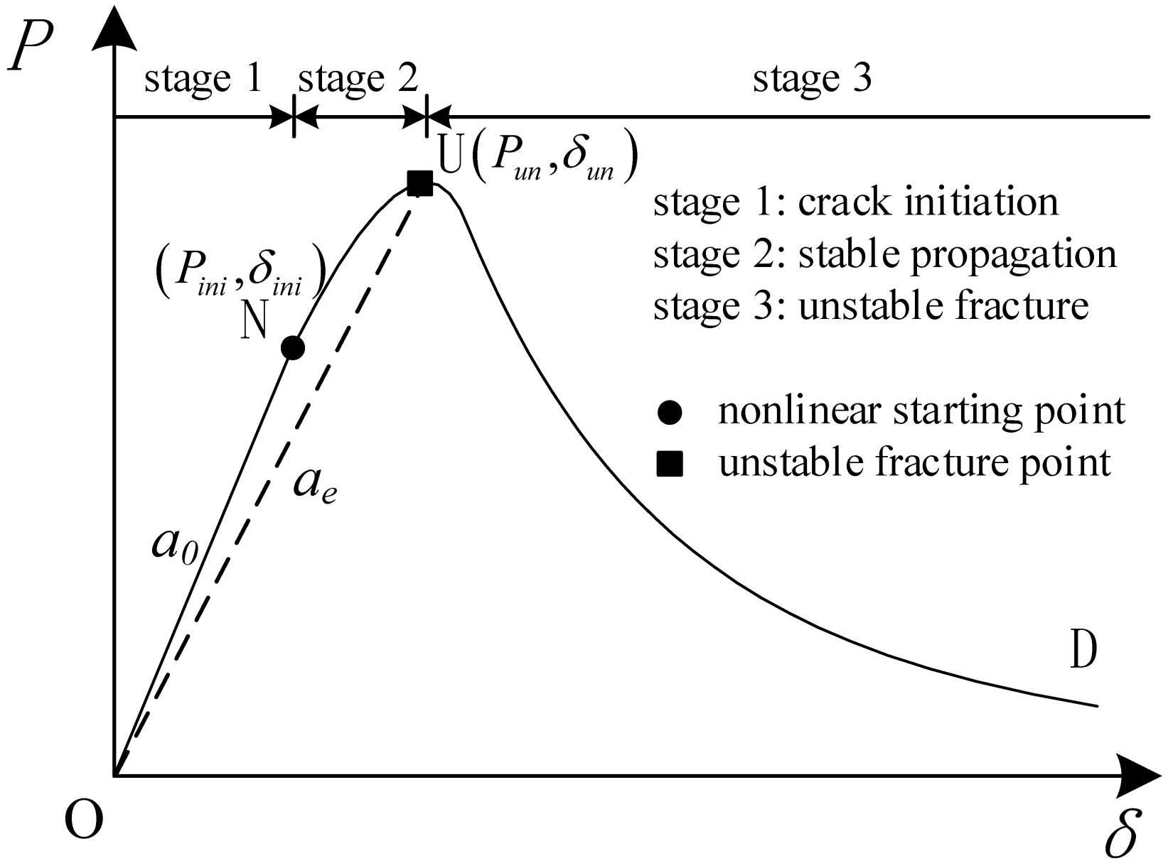
- The nonlinear characteristic of the P–δ curve is caused by the fracture process zone;
- (2)
- The fracture analysis of concrete is calculated by the elastic equivalent method, where the equivalent crack is composed of a free crack and an equivalent fictitious crack.
- (1)
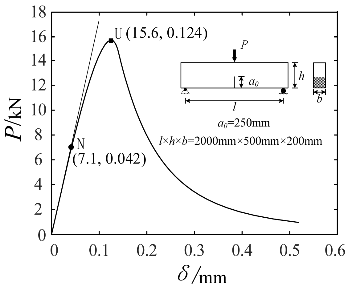
- Measure the crack width δ and the load P;
- (2)
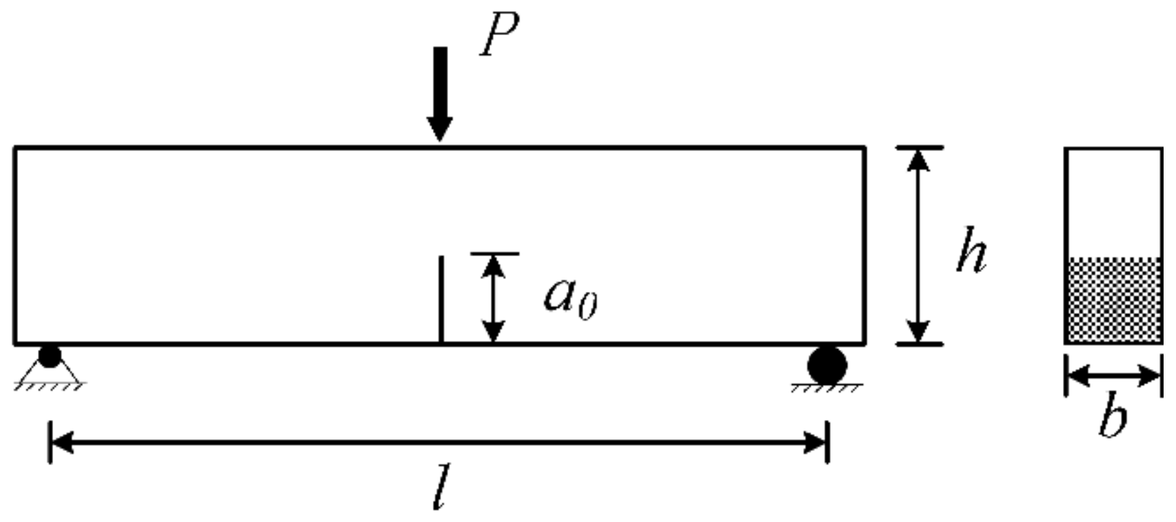
- Calculate the equivalent crack depth ae by solving the following linear elastic fracture equation:where l, h, and b are the length, height, and width of the specimen, respectively; E is the modulus of elasticity; and V(·) is the shape function.
- (3)
- Calculate the stress intensity factor by the following linear elastic fracture formula:where F(·) is the shape function.
- (1)
- When K < Kini, crack initiation stage: the crack width increases linearly with the load;
- (2)
- When Kini ≤ K < Kun, stable propagation stage: the fracture process zone extends steadily;
- (3)
- When K ≥ Kun, unstable fracture stage: the crack develops drastically.
3. Modified Double-K Fracture Criterion for Cracks in Tunnel Linings
- (1)
- Measure the crack width δ and the free crack depth a0;
- (2)
- Obtain two fracture toughness values and then transform them into the crack width indices;
- (3)
- Evaluate the mechanical state of the lining cracks by the following criteria:
- (a)
- When δ < δini, crack initiation stage: the crack width increases linearly with the load;
- (b)
- When δini ≤ δ < δun, stable propagation stage: the fracture process zone extends steadily;
- (c)
- When δ ≥ δun, unstable fracture stage: the crack develops drastically.
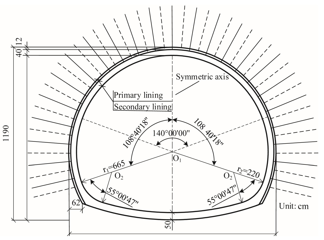
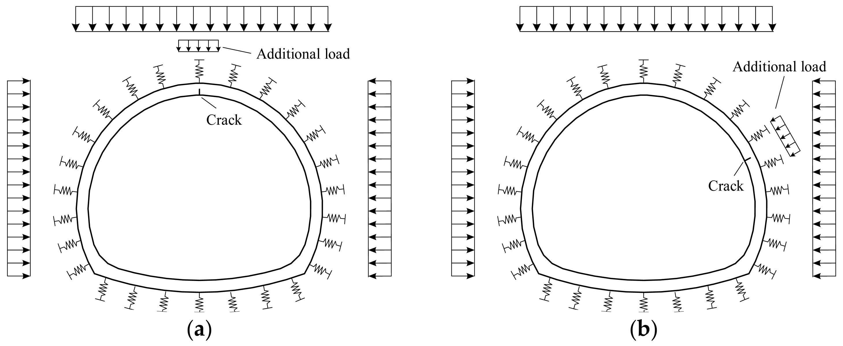
4. Numerical Experiments of the Fracture Behavior of Tunnel Linings
4.1. Basic Parameters of the Numerical Experiments
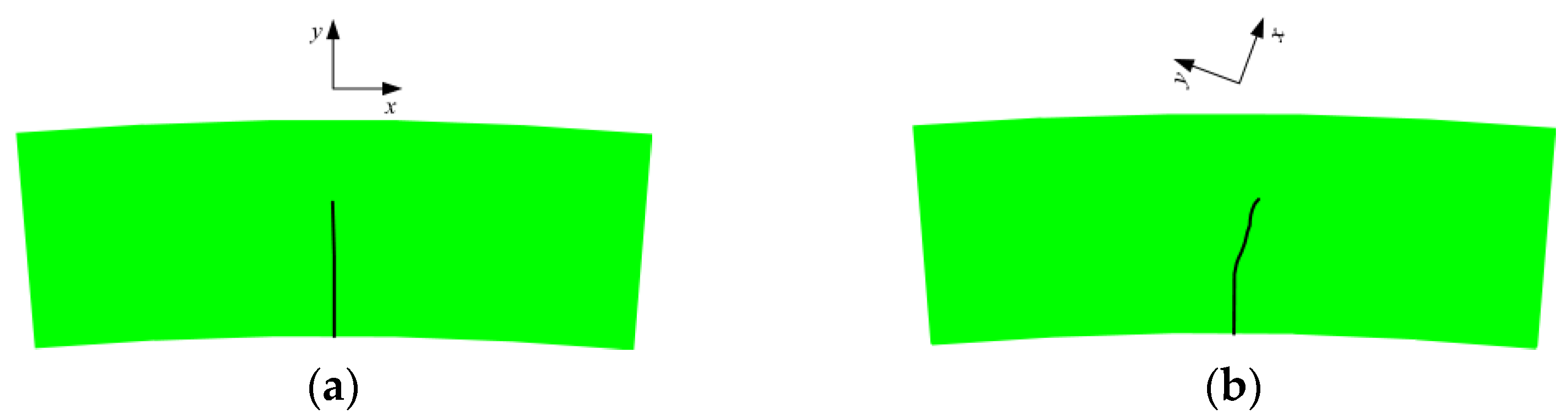
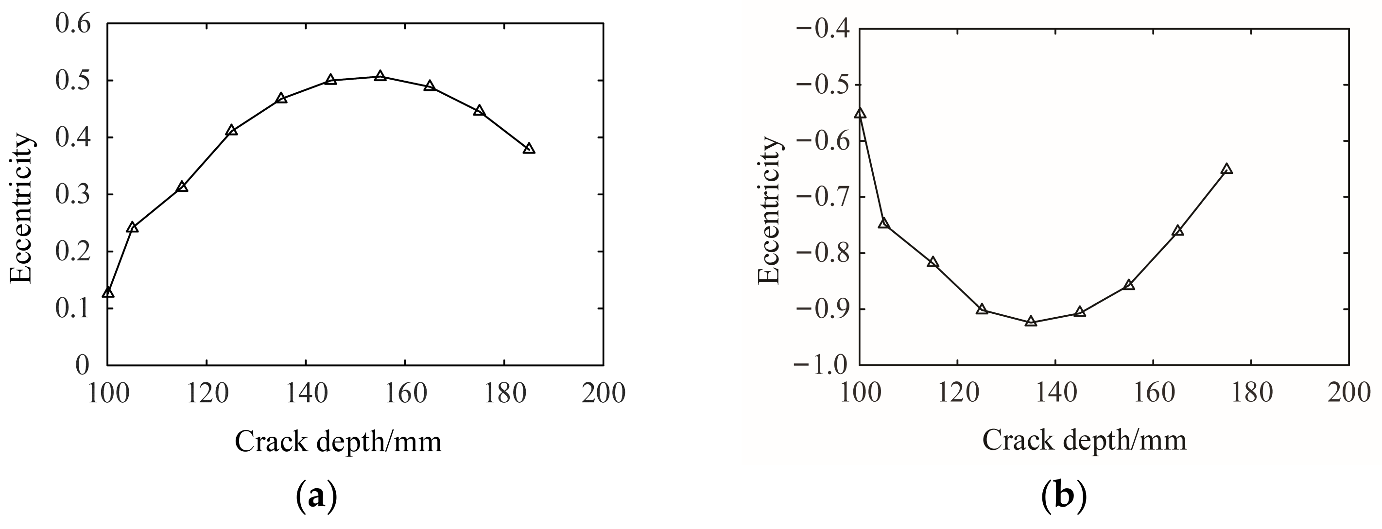
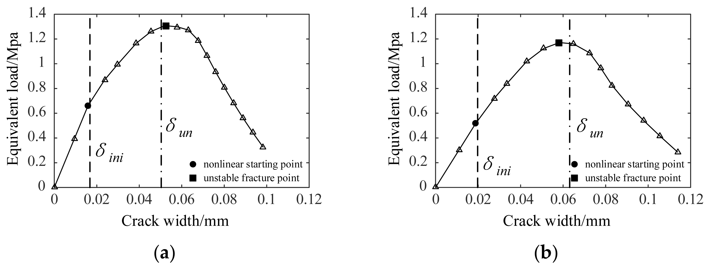
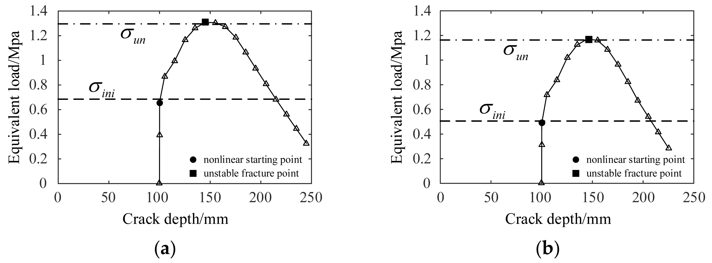
4.2. Analysis of the Fracture Process of Tunnel Linings
5. Conclusions
Author Contributions
Funding
Institutional Review Board Statement
Informed Consent Statement
Data Availability Statement
Conflicts of Interest
List of Symbols
| a0 | Initial crack depth |
| ae | Equivalent crack depth |
| E, μ | Elastic modulus and Poisson’s ratio |
| ft | Tensile strength |
| F, V, fM, fN, vM, vN | Shape functions |
| K | Stress intensity factor |
| Kini, Kun | Initiation and unstable fracture toughness |
| Kc | Additional fracture toughness caused by the cohesive force |
| l, h, b | Length, height, and width of the specimen |
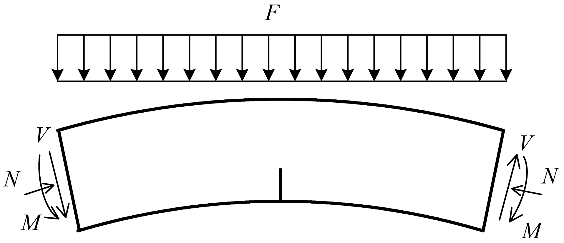
| M, N | Bending moment and axial force |
| P | External load |
| w0 | Ultimate crack width |
| w | Crack width of the physical crack tip |
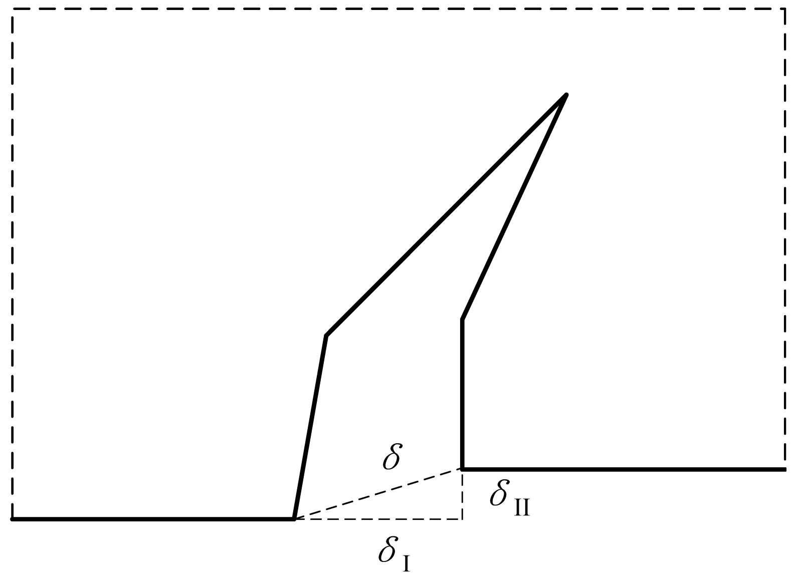
| δ | Crack width |
| σe | Equivalent load |
References
- Fang, Q.; Wang, G.; Yu, F.; Du, J. Analytical algorithm for longitudinal deformation profile of a deep tunnel. J. Rock Mech. Geotech. Eng. 2021, 13, 845–854. [Google Scholar] [CrossRef]
- Li, P.; Wei, Y.; Zhang, M.; Huang, Q.; Wang, F. Influence of non-associated flow rule on passive face instability for shallow shield tunnels. Tunn. Undergr. Space Technol. 2022, 119, 104202. [Google Scholar] [CrossRef]
- Chiu, Y.C.; Lee, C.H.; Wang, T.T. Lining crack evolution of an operational tunnel influenced by slope instability. Tunn. Undergr. Space Technol. 2017, 65, 167–178. [Google Scholar] [CrossRef]
- Wang, T.-T. Characterizing crack patterns on tunnel linings associated with shear deformation induced by instability of neighboring slopes. Eng. Geol. 2010, 115, 80–95. [Google Scholar] [CrossRef]
- Japan Road Association. Manual on Management and Maintenance of Road Tunnels; Japan Road Association: Tokyo, Japan, 1993. [Google Scholar]
- The Professional Standards Compilation Group of People’s Republic of China. Highway Tunnel Maintenance Technical Specifications; China Communications Press: Beijing, China, 2003. [Google Scholar]
- Fang, H.; Zhang, D.; Fang, Q.; Wen, M. A generalized complex variable method for multiple tunnels at great depth considering the interaction between linings and surrounding rock. Comput. Geotech. 2021, 129, 103891. [Google Scholar] [CrossRef]
- Zhang, D.; Xu, T.; Fang, H.; Fang, Q.; Cao, L.; Wen, M. Analytical modeling of complex contact behavior between rock mass and lining structure. J. Rock Mech. Geotech. Eng. 2022. [Google Scholar] [CrossRef]
- Fang, H.; Zhang, D.; Fang, Q. A semi-analytical method for frictional contact analysis between rock mass and concrete linings. Appl. Math. Model. 2022, 105, 17–28. [Google Scholar] [CrossRef]
- Khoteev, E.; Zertsalov, M.; Merkin, V. The determination of crack resistance of the circular shaped fiber reinforced concrete tunnel lining by means of linear fracture mechanics. In Proceedings of the International Multidisciplinary Scientific GeoConference: SGEM, Vienna, Austria, 27–29 November 2017; pp. 873–880. [Google Scholar]
- Amorim, D.L.D.F.; Proenca, S.P.; Florez-Lopez, J. Simplified modeling of cracking in concrete: Application in tunnel linings. Eng. Struct. 2014, 70, 23–35. [Google Scholar] [CrossRef]
- Brameshuber, W.; Hilsdorf, H.K. Size Effects in the Experimental Determination of Fracture Mechanics Parameters; NATO-Advanced Research Workshop: Dordrecht, The Netherlands, 1984. [Google Scholar]
- Bažant, Z.P.; Donmez, A. Extrapolation of short-time drying shrinkage tests based on measured diffusion size effect: Concept and reality. Mater. Struct. 2016, 49, 411–420. [Google Scholar] [CrossRef] [Green Version]
- Carloni, C.; Cusatis, G.; Salviato, M.; Le, J.; Hoover, C.G.; Bazant, Z.P. Critical comparison of the boundary effect model with cohesive crack model and size effect law. Eng. Fract. Mech. 2019, 215, 193–210. [Google Scholar] [CrossRef]
- Dönmez, A.; Rasoolinejad, M.; Bažant, Z.P. Size Effect on FRP External Reinforcement and Retrofit of Concrete Structures. J. Compos. Constr. 2020, 24, 04020056. [Google Scholar] [CrossRef]
- Kirane, K.; Bazant, Z.P. Size effect in Paris law for quasibrittle materials analyzed by the microplane constitutive model M7. Mech. Res. Commun. 2015, 68, 60–64. [Google Scholar] [CrossRef]
- Bažant, Z.P.; Oh, B.H. Crack band theory for fracture of concrete. Matériaux Et Constr. 1983, 16, 155–177. [Google Scholar] [CrossRef] [Green Version]
- Bažant, Z.P.; Yu, Q. Size effect on strength of quasibrittle structures with reentrant corners symmetrically loaded in tension. J. Eng. Mech. 2006, 132, 1168–1176. [Google Scholar] [CrossRef]
- Bažant, Z.P.; Yu, Q. Universal Size Effect Law and Effect of Crack Depth on Quasi-Brittle Structure Strength. J. Eng. Mech. 2009, 135, 78–84. [Google Scholar] [CrossRef] [Green Version]
- Li, Z.; Shah, S.P. Localization of microcracking in concrete under uniaxial tension. ACI Mater. J. 1994, 91, 372–381. [Google Scholar]
- Hillerborg, A.; Modeer, M.; Petersson, P.E. Analysis of crack formation and crack growth in concrete by means of fracture mechanics and finite elements. Cem. Concr. Res. 1976, 6, 773–782. [Google Scholar] [CrossRef]
- Kaplan, M.F. Crack propagation and the fracture of concrete. J. Am. Concr. Inst. 1961, 58, 591–610. [Google Scholar]
- Shah, S.P.; Gopalaratnam, V.S. Softening response of plain concrete in direct tension. ACI Mater. J. 1985, 82, 310–323. [Google Scholar]
- Xu, S.; Reinhardt, H.W. Determination of double-Determination of double-K criterion for crack propagation in quasi-brittle fracture Part I: Experimental investigation of crack propagation. Int. J. Fract. 1999, 98, 111–149. [Google Scholar] [CrossRef]
- Xu, S.; Reinhardt, H.W. Determination of double-K criterion for crack propagation in quasi-brittle fracture, Part II: Analytical evaluating and practical measuring methods for three-point bending notched beams. Int. J. Fract. 1999, 98, 151–177. [Google Scholar] [CrossRef]
- Tang, T.; Shah, S.P.; Ouyang, C. Fracture Mechanics and Size Effect of Concrete in Tension. J. Struct. Eng. 1992, 118, 3169–3185. [Google Scholar] [CrossRef]
- Jenq, Y.; Shah, S.P. Two Parameter Fracture Model for Concrete. J. Eng. Mech. 1985, 111, 1227–1241. [Google Scholar] [CrossRef]
- Xu, S.; Reinhardt, H.W. Determination of double-K criterion for crack propagation in quasi-brittle fracture, Part III: Compact tension specimens and wedge splitting specimens. Int. J. Fract. 1999, 98, 179–193. [Google Scholar] [CrossRef]
- Paris, P.C.; Tada, H.; Irwin, G.R. The Stress Analysis of Cracks Handbook; ASME Press: New York, NY, USA, 2000. [Google Scholar]
- Jenq, Y.S.; Shah, S.P. Mixed-mode fracture of concrete. Int. J. Fract. 1988, 38, 123–142. [Google Scholar] [CrossRef]
- Jenq, Y.S.; Shah, S.P. Features of mechanics of quasi-brittle crack propagation in concrete. In Current Trends in Concrete Fracture Research; Bažant, Z.P., Ed.; Springer: Dordrecht, The Netherlands, 1991; pp. 103–120. [Google Scholar]
- Rabinovich, D.; Givoli, D.; Vigdergauz, S. XFEM-based crack detection scheme using a genetic algorithm. Int. J. Numer. Methods Eng. 2007, 71, 1051–1080. [Google Scholar] [CrossRef]
- Fang, H.; Zhang, D.; Zhou, M.; Fang, Q.; Wen, M. A contact algorithm for cohesive cracks in the extended finite element method. Int. J. Numer. Methods Eng. 2020, 121, 2747–2766. [Google Scholar] [CrossRef]
- Fang, H.; Zhang, D.; Zhou, M.; Fang, Q.; Wen, M.; Hu, X. A virtual interface-coupled extended finite element method for three-dimensional contact problems. Int. J. Numer. Methods Eng. 2021, 122, 386–402. [Google Scholar] [CrossRef]
- Fang, H.; Zhang, D.; Fang, Q.; Cao, L.; Wen, M. An efficient patch-to-patch method for coupling independent finite element subdomains with intersecting interfaces. Comput. Methods Appl. Mech. Eng. 2022, 388, 114209. [Google Scholar] [CrossRef]
- Belytschko, T.; Black, T. Elastic crack growth in finite elements with minimal remeshing. J. Numer. Methods. Eng. 1999, 45, 601–620. [Google Scholar] [CrossRef]
- Moës, N.; Dolbow, J.; Belytschko, T. A finite element method for crack growth without remeshing. Int. J. Numer. Methods Eng. 1999, 46, 131–150. [Google Scholar] [CrossRef]
- Wen, M.; Fang, Q.; Zhang, D.L.; Fang, H.C. A numerical algorithm for multiple cracks propagation in concrete structure. Struct. Concr. 2020, 21, 2168–2177. [Google Scholar] [CrossRef]
- Cedolin, L.; Poli, S.D.; Iori, I. Tensile Behavior of Concrete. J. Eng. Mech. 1987, 113, 431–449. [Google Scholar] [CrossRef]


| E/Gpa | μ | ft/Mpa | w0/μm | Kini/Mpa∙m1/2 | Kun/Mpa∙m1/2 |
|---|---|---|---|---|---|
| 34.2 | 0.2 | 4 | 35 | 0.54 | 1.39 |
Publisher’s Note: MDPI stays neutral with regard to jurisdictional claims in published maps and institutional affiliations. |
© 2022 by the authors. Licensee MDPI, Basel, Switzerland. This article is an open access article distributed under the terms and conditions of the Creative Commons Attribution (CC BY) license (https://creativecommons.org/licenses/by/4.0/).
Share and Cite
Huang, C.; Li, X.; Wen, M. Analysis of Crack Formation and Growth in Tunnel Linings Using Double-K Fracture Criterion. Appl. Sci. 2022, 12, 1064. https://doi.org/10.3390/app12031064
Huang C, Li X, Wen M. Analysis of Crack Formation and Growth in Tunnel Linings Using Double-K Fracture Criterion. Applied Sciences. 2022; 12(3):1064. https://doi.org/10.3390/app12031064
Chicago/Turabian StyleHuang, Chengjun, Xinrui Li, and Ming Wen. 2022. "Analysis of Crack Formation and Growth in Tunnel Linings Using Double-K Fracture Criterion" Applied Sciences 12, no. 3: 1064. https://doi.org/10.3390/app12031064
APA StyleHuang, C., Li, X., & Wen, M. (2022). Analysis of Crack Formation and Growth in Tunnel Linings Using Double-K Fracture Criterion. Applied Sciences, 12(3), 1064. https://doi.org/10.3390/app12031064