Abstract
The forward kinematics in parallel manipulators is a mathematically challenging issue, unlike serial manipulators. Kinematic constraint equations are non-linear transcendental equations that can be reduced to algebraic equations with appropriate transformations. For this reason, sophisticated and time-consuming methods such as the Bezout method, the Groebner bases method, and the like, are used. In this paper, we demonstrate that these equations can be solved by non-complicated mathematical methods for some special types of manipulators such as the 3-3 and 6-3 types of Stewart platforms, and the 3-RRR planar parallel manipulator. Our first method is an analytical approach that exploits the special structure of kinematic constraint equations and yields polynomials of 32nd and 16th order, as mentioned in the previous works. In the second method, an error function is defined. This error function is employed to find the most appropriate initial values for the non-linear equation solver which is used for solving kinematic constraint equations. Determining the initial values in this manner saves computation time and guarantees fast convergence to real solutions.
1. Introduction
Parallel manipulators, either planar or spatial, have been used for the last three decades due to their higher rigidity, accuracy, and payload capacity. However, they have smaller workspaces than serial manipulators. The Stewart platform (SP henceforth) is a well-known type of spatial manipulator. These manipulators have one fixed and one moving platform connected to each other by actuators, as seen in Figure 1. For this type of manipulator, various assembly modes are available, such as 6-6, 6-3, 3-3, etc. [1]. These numbers are attributed to the number of joints on the fixed and moving platforms, respectively. Contrary to serial manipulators, the forward kinematics of parallel manipulators are more complex than the inverse kinematics, hence many authors have focused on the forward kinematics of the SP, along with other parallel manipulators [2]. In the forward (direct) kinematics, loop equations and rigidity conditions are utilized to transition from actuators’ kinematic parameters to those of the moving platform, i.e., to the pose, velocity, and acceleration of the moving platform.
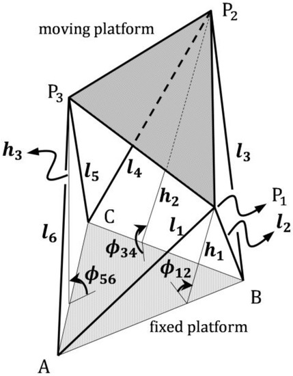
Figure 1.
General view of the 3-3 Stewart platform.
Vast literature exists on parallel manipulators, especially on the Stewart platform. However, here some early published and remarkable papers will be mentioned, as fundamental methods are developed and proposed in these works. For detailed literature on the Stewart platform, the paper by Dasgupta et al. can be referred to [2]. Lee et al. studied a 3-dof spatial parallel platform in which linear actuators are connected to the fixed plate by revolute joints [3]. Inspired by this work, Nanua et al. developed a solution procedure for the 6-3 and 3-3 Stewart platforms [4]. Merlet demonstrated that a 6-dof Stewart platform with a triangle-shaped moving platform leads to a 16th-degree polynomial [5]. In another paper, Merlet used symbolic computation to determine the solution polynomial of minimal degree and singular configurations of parallel manipulators [6]. Rouillier proposed a method to count the real roots of the solution polynomial [7]. Wampler also studied the forward kinematics of a general Stewart platform using Soma coordinates [8]. These papers differ from each other in the methods used or proposed.
Parallel planar manipulators (PPM) usually have three dof (degrees-of-freedom) unless redundant freedom is desired. Several design variants are encountered in the relevant literature, such as 3 RPR or 3 RRR. Gosselin et al. [9] proposed a new architecture for the 3-dof planar manipulator. Merlet studied the forward kinematics of different types of planar parallel manipulators [10]. Gosselin and Merlet obtained the maximum number of solutions for the forward kinematics of planar parallel manipulators using Sturm’s theorem [11]. They showed that even though the proposed polynomial has six roots, only four solutions exist because the two left solutions are not feasible. Hamdoun et al. performed inverse kinematic model of a 3RRR parallel robot and did workspace analysis [12]. Kinematic and dynamic analysis of a 3-RRR parallel planar robot using four different neural network algorithms was carried out [13]. Toz [14] dealt with the kinematic and singularity-free workspace analysis of a 3-dof asymmetrical planar parallel robot (3-RPR) mechanism.
For both spatial and planar parallel manipulators, the forward kinematics analysis leads to a set of non-linear equations based on satisfying kinematic constraint equations. These equations can be converted into algebraic equations by appropriate transformations. Researchers have tried to solve these equations using different methods, such as Bezout’s method [15,16], the Groebner bases method [17,18,19], the interval analysis method [20,21], the continuation approach [8], algebraic elimination method [22], and numerical methods such as the Newton–Raphson method [16,23], or using the conformal geometric algebra framework [24]. However, in some special cases, this set of equations can be solved with simpler techniques [4]. Nanua showed in 1990 that the forward kinematics of a 6-3 SP can be solved by finding the roots of a 16th-order polynomial, which Charentus [25] already presented in 1989. This is the case in the 3-3 SP (also in the 6-3 SP).
As several papers about the forward kinematics of parallel manipulators have been published lately, they focus on the issues such as the use of machine learning [26], transforming the forward kinematics problem to a suitable inverse kinematics analysis [27], or improving and optimizing the weighting factor of a neural network for the forward kinematics of a Stewart platform [28] rather than proposing or developing new analytical or analytical–numerical combined methods.
As is seen in the literature mentioned above, various methods have been proposed to solve forward kinematics problem, which can be separated into two main groups: closed-form solution (algebraic) methods and numerical methods. The details of the algebraic techniques proposed so far will not be given here because they are well-known in the relevant community and are beyond the scope of the paper. Regarding numerical methods, the Newton–Raphson method is the most common among these. In this method, once the user assigns the initial values to the unknowns of the problem, this method gives just one solution. The method is highly sensitive to initial values. Sometimes, it may converge toward an uninterested solution far from the expected, or even it might diverge. Finding only one solution at once is the weakness of this method.
Although the forward kinematics problem of parallel manipulators has been intensively studied from various aspects, and the issue appears completed, it is still possible to develop new approaches specific to some manipulator architectures but extendable to more general assembly forms. Motivated by this fact, in the present paper, we propose two new and easy to implement methods for the forward kinematics of parallel manipulators of some specific types. Both methods can be used as a general solution procedure for 3-RRR planar manipulators, whereas they are applicable to the 3-3 or 6-3 type Stewart platforms only. The process in our both methods is the same as that in the present literature until kinematic constrain equations are obtained. The first of our methods is an analytical approach, while the second one is a combined analytical–numerical method. We call these methods “the Solve-and-Substitute-Method” (the SSM henceforth) and “the Error-Function-Method” (the EFM in short). However, our methods (especially the SSM) differ from those existing in the literature, in that they exploit the special structure of the constraint equations for the manipulators considered.
In both the polynomial-based methods in the current literature and the method we propose here (the SSM), the problem of finding the position parameters (coordinates) is reduced to obtaining the roots of a polynomial that is a function of only one of these coordinates. However, our method, the SSM and the EFM differ from those existing in the literature, in that they exploit the special structure of the kinematic constraint equations for the manipulators considered. The steps of the SSM can be explained as follows. We have three constraint equations for both types of manipulators studied. These equations have three unknowns, say λ, µ, and ν. Each of these equations includes just two of these unknowns. The power of these unknowns in the equation is at most two. In this case, two of these equations are considered, in which one unknown is common, say λ. Hence, if this common unknown is considered as a parameter, these two equations can be viewed as polynomials of second order in terms of the remaining unknowns µ and ν. The roots of these polynomials can be found in λ. Afterwards, these roots are substituted in the third equation in which only µ and ν appear, and a polynomial of 32nd order. The real roots of this polynomial can correspond to possible poses of the manipulator. As is easily seen, our method is based on basic mathematical operations and can be used as a general solution method for 3-RRR planar manipulator, while it is restricted to the 3-3 and 6-3 types of assembly modes of the Stewart manipulator.
The second method we propose, the EFM, can be explained as follows. Our starting point is again the set of kinematic constraint equations. As usual, we construct an error function. In the current literature, one usually tries to find the values of three unknowns, which makes the kinematic constraint equations zero. To this end, any non-linear equation solver can be used, such as the Newton–Raphson method assigning some initial values, which are usually random. In solving this set of non-linear equations, our method differs from the previous works, in that the search interval of λ (the unknown chosen as parameter) is carefully determined. The values of λ are selected in such a way that the roots of the equations in which λ is the assumed parameter take the real values. To this end, the expressions of the discriminants in the root formulas are plotted in λ, and the common interval of λ, in which discriminants are positive, is determined. The error function is plotted using the values of λ within this interval, and the λ values corresponding to the minima of this function are used as the initial values for the non-linear equation solver. Thus, one avoids randomly searching for real solutions, which also reduces the solution time. The details of both methods (the SSM and the EFM) will be given in the following section.
To sum up, our methods are not based on the more sophisticated techniques of the mathematical analysis. In the first method one needs just the theory of second-degree polynomials, while the second method accelerates and guarantees the convergence when the real poses of manipulator are to be found by numerical techniques, such as the Newton–Raphson method.
The paper is organized as follows: Under the headline of Materials and Methods, each method will be explained, and then its implementation in two manipulators will be shown separately. Two numerical applications for each method will be given in the Numerical Examples section.
2. Materials and Methods
2.1. The SSM
The implementation of this method will be explained first for the 3-3 type SP (also for the 6-3 type SP) and later for the 3-RRR planar manipulator.
2.1.1. The Implementation of the SSM in the 3-3 Type SP
This type of SP is shown in Figure 1 schematically.
As seen in Figure 1, ’s (i = 1,...,6) are the length of actuators, while ’s (i = 1,2,3) are the lengths of the mid-perpendiculars, which can be called instantly equivalent actuators. , , and are the angles which the perpendiculars make with the ground.
In the case of a 3-3 or 6-3 SP, the kinematic constraint equations are obtained in the following form (to see in detail how these equations are derived, refer to [4,16]):
where λ, μ, and ν are unknowns that are tangents of half the angles , and , Figure 1. , , and ’s are constant coefficients, including some dimensions of the manipulator.
When Equations (1)–(3) are carefully considered, it is seen that each equation contains only two unknowns of, at most, second degree; hence, each equation can be seen as a second-degree polynomial in terms of both unknowns appearing in that equation. Any two of these equations can be selected, provided that one of the unknowns is common in both equations. Let this common unknown be λ. Then, this unknown can be viewed as a parameter in both equations, in our case Equations (1) and (3). Thus, these equations become the second-degree polynomials in terms of remaining unknowns µ and ν, as the coefficients of these unknowns are viewed as functions of λ. One gets two roots for each polynomial: () and (). Note that these roots are again functions of λ. Hence, four variants are obtained for four root pairs, i.e., (), (), (), (). The last step is to substitute these root pairs in the remaining third equation, in Equation (2), in which the unknown selected as a parameter does not appear. In this method, since we need two equations in which the unknown selected as a parameter (here λ) is common, we slightly modified Equation (3) and re-ordered Equations (1)–(3) as follows:
where
From Equations (4) and (6), which can be considered second-degree polynomials in terms of and , respectively, the roots of both polynomials are obtained as below:
where
Since Equations (4) and (6) have two roots (i.e., Equations (8) and (9)), pairing these roots two by two gives four variants: (), (), (), (). One of these variants is substituted in Equation (5), and a polynomial in λ is obtained. It is possible to show that the same polynomial is obtained regardless of the variant chosen. (Negative or positive sign in Equations (8) and (9) does not affect the final polynomial in Equation (16)). Here, the variants and are used. Consequently, if the roots are substituted in Equation (5) and multiplied both sides by yields:
Equation (11) can be rewritten in the following compact form:
where
However, Equation (12) still includes square root terms. To eliminate them, we write Equation (12) as follows:
If we take the square of both sides of Equation (14), we obtain the following:
Now, taking the square of both sides of Equation (15) once more, one finds:
Equation (16) will give us a polynomial of λ. The maximum order of λ in the expressions given by (16) can be found by some consideration: The order of λ in the terms in Equation (16) is obtained by inspection of their explicit expressions given by Equation (13) as follows:
We can find the following:
As Equation (18) implies, the expression given by Equation (16) is a polynomial of maximum 32nd degree in λ. Since the order of all terms in λ in this polynomial is even, the degree of the polynomial can be reduced to 16 via a simple variable transformation, for instance, . Note that the degree of the polynomial can also be obtained using the symbolic toolbox of some engineering programs such as MATLAB or Maple. The explicit expression of this polynomial is too long, and therefore it is not given here due to the space limitation. However, the polynomial obtained here is exactly the same symbolic expression found by Nanua et al. [4] using the Bezout method.
The roots of this polynomial can be obtained only numerically due to its higher order. For each λ, Equations (8) and (9) give two values for each of μ and ν. It must be checked which variant of (μ,ν) satisfies Equations (4)–(6) simultaneously. The values that we are interested in for this problem are only real, positive ones.
2.1.2. The Implementation of the SSM in the 3-RRR Planar Manipulator
A general view of the 3-RRR planar manipulator and its dimensions and parameters are given in Figure 2.
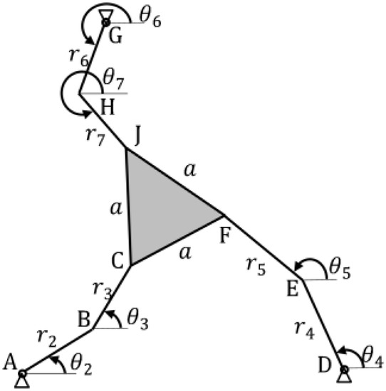
Figure 2.
General views of the 3-RRR planar manipulator.
In Figure 2, , and are called active joint angles because they are coordinates defining the positions of driving links while , , and are passive joint angles. Mathematical operations similar to what is done for the SP are also carried out for this manipulator. Since the SSM is a general method for this type of planar manipulator, for the completeness of the subject, it will be explained here in detail how to derive the kinematic constraint equations. From Figure 2, the coordinates of points C and F of the planar manipulator in Figure 2 are easily written as follows:
The distance between C and F is:
Equation (20) can also be written as
where the constant coefficients are:
Similarly, the coordinates of J and C are:
The distance between J and C is:
Equation (24) can also be written as
where
Finally, the distance between J and F is:
Using the coordinates of points J and F given above in Equations (19) and (23), the following equation is found:
where
Now, let the following variables define:
If the sine and cosine terms in Equations (21), (25), and (28) are written in the new variables given in Equation (30), the following equations are found:
where
As readily seen, the equation set of Equations (31) to (33) for the 3-RRR planar manipulator has the same form as in Equations (4)–(6). Here again, in Equations (31) and (32), λ can be selected as a parameter. The roots of both polynomials in μ and ν, respectively, can be obtained as functions of the parameter λ. The process after this stage is the same as is done for the SP.
2.2. The EFM
In this method, we define an error function as follows:
where f2 is the left-hand side of Equation (5) for SP and Equation (32) for 3-RRR, respectively. In fact, the error function could be defined as . In this case, and would be the left-hand sides of Equations (4)–(6) for SP, and Equations (31)–(33) for 3-RRR, respectively. However, in our method, since and values will be calculated in , as is given in Equations (8) and (9), and will automatically be zero, so it will be sufficient to use only f2 in the error function. In addition, since the range of values will be selected in such a manner that the discriminants q and v in Equations (8) and (9) are positive, there will not be problems with extracting complex roots as in SSM. The only task of the error expression we have defined above is to determine the appropriate initial values for the Newton–Raphson method, which is used to solve three equations with three unknowns, namely, constraint equations. These appropriate initial values are obtained from the values corresponding to minima of the error function. This ensures that we do not miss the solutions which could not be found if the Newton–Raphson method was directly used with inaccurately determined initial conditions. Details will be given below.
2.2.1. Implementation of the Method in the SP
For the SP, the components in the error function given by Equation (37) are as follows:
Note that Equations (38)–(40) are the left-hand sides of Equations (4)–(6). At this point, our method distinguishes from the numerical methods mentioned in the previous works. To seek the possible configurations of the manipulator more consciously, we control the discriminants q and v in Equations (8) and (9) instead of trying to equate the error functions to zero by assigning random initial values. The discriminants q and v must be positive to guarantee real values for µ and ν. These discriminants are as follows:
It is easily seen that the discriminants are fourth-order polynomials in and include only even-order terms. Hence, when these expressions are plotted versus , they are represented by the curves symmetric with respect to the vertical axis, as seen in Figure 3. In the region of ≥ 0, the base of the area, which is enclosed by positive parts of both curves, gives us the interval of λ necessary for real μ and ν values (the shaded area in Figure 3).
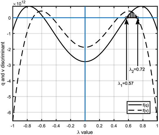
Figure 3.
Variations of q and v versus λ for the 3−3 type Stewart platform.
2.2.2. Implementation of the Method in the 3−RRR Planar Manipulator
For this manipulator, the components in the error function similar to Equations (38)–(40) are as follows:
Here, Equations (43)−(45) are the left-hand sides of Equations (31)−(33). For the planar manipulator, the graphics of discriminants are shown in Figure 4. Different from Figure 3, here, the sought interval of λ is determined only by the curve related to q because these curves do not intersect, as seen in Figure 4.
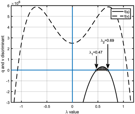
Figure 4.
Variations of q and v versus λ for the planar manipulator.
3. Numeric Examples
In this section, two numerical examples for each method will be given to show the implementation of both methods. Firstly, the examples related to the use of the SSM will be treated.
3.1. Numerical Examples for the SSM
3.1.1. Numerical Application of the SSM to the Stewart Platform
The physical parameters of the Stewart platform manipulator are seen in Figure 1, and the coefficients in Equations (4)–(6) are given in Table 1 and Table 2, respectively.

Table 1.
The physical parameters of the SP.

Table 2.
Coefficients of the Equations (4)–(6) for the SP.
From Equations (8) and (9), one finds:
Substituting these expressions in Equation (5) and carefully rearranging yields the following polynomial:
This polynomial is the explicit form of Equation (16). The roots of this 32nd-degree polynomial are given in Table 3.

Table 3.
Roots of the polynomial in Equation (33).
To guarantee the physically possible poses of the SP, only the positive and real roots in Table 3 must be considered (solution 3 and solution 4 in Table 3). For each λ value, one can calculate two roots for μ using Equation (8) and two roots for ν using Equation (9). One must check which variants satisfy all the Equations (4)–(6). The feasible (λ, μ, ν) variants are shown in Table 4.

Table 4.
Physically meaningful solutions (first method).
3.1.2. Numerical Application of the SSM to the 3-RRR Planar Manipulator
The physical parameters of the 3-RRR planar manipulator in Figure 2 and the coefficients in Equations (31)–(33) are given in Table 5 and Table 6, respectively.

Table 5.
Physical dimensions for the planar manipulator.

Table 6.
Coefficients of the Equations (4)–(6) for the planar manipulator.
Using the expressions, the following 32nd degree polynomial is found:
The roots of the expression above are given in Table 7.

Table 7.
Roots of the polynomial.
As seen from Table 7, there are ten real number solutions of λ. Complex ones are rejected. The polynomial has multiple roots. In short, there are four different real roots of the polynomial: λ1 = −0.97, λ2 = 0.97, λ3 = 0.498, and λ4 = 0.67.
For each λ, two roots are obtained for each of μ and ν, as seen in Table 8.

Table 8.
(λ, μ, ν) solutions.
Table 8 shows that eight roots (rows 1–4 and 13–16) are complex numbers. They are rejected. Eight of the roots are real numbers; eight possible solutions exist. However, it should be checked if the rigidity conditions satisfy each solution set of λ, μ, ν. After this control, it is seen that only the λ, μ, ν triplets given in Table 9 correspond to feasible solutions.

Table 9.
Possible (λ, μ, ν) solutions.
3.2. Numerical Examples for the EFM
3.2.1. The Numerical Application of the EFM to the 3-3 Type SP
From Figure 3, the interval of λ values that lead to real roots for μ and ν are found as 0.573 ≤ λ ≤ 0.722. λ is altered within the obtained interval, and the error function is plotted versus λ, Figure 5. From this figure, the minima of the error function are obtained.
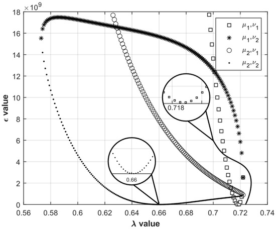
Figure 5.
The graphics of ϵ versus λ.
The error function has two minima about λ = 0.66 and λ = 0.72. In this case, μ and ν are calculated from Equations (8) and (9), corresponding to these values of λ. Given these triplets of (λ, μ, ν), the real solution set is searched using a suitable algorithm (for example, the Newton–Raphson iteration method or fsolve, a built-in function in MATLAB)). The results obtained are given in Table 10. From the comparison of Table 10 and Table 4, it is immediately noticeable that both methods provide the same results.

Table 10.
Physically meaningful solutions (the EFM).
3.2.2. Implementation of the EFM in the 3-RRR Manipulator
Following the steps for the 3-RRR planar manipulator, one can find the determinants q and v as:
As seen in Figure 4, the value of λ has to be between 0.47–0.69.
By changing the λ value in that interval and finding two roots of μ and ν values, the resulting figure is given in Figure 6. The error function in Equation (37) is plotted for four variants.
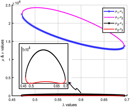
Figure 6.
The variation of the error function over λ.
4. Conclusions
The forward kinematic analysis of parallel manipulators leads to transcendental equations which can be converted into algebraic ones. Researchers have tried to develop more general solution methods using mathematical analysis techniques, such as the Bezout method, the Groebner bases, and interval analysis. The Bezout method defines additional variables and equations using the constraint equations and original unknowns. In this method the problem is reduced to solving a homogeneous system of linear equations. The elements of the coefficient matrix of this system depend on only one of the original unknowns. Setting the determinant of the coefficient matrix equal to zero yields a polynomial. Although this technique can be applied in manipulators of any assembly mode, it is time-consuming. Similarly, the Groebner bases technique defines new variables and yields new equations using this transformation. The structure of these new equations is similar to the form of a system of linear equations after the Gauss Elimination procedure is applied.
In this paper, however, we have demonstrated that these equations can be solved more directly using simple mathematical operations for certain assembly forms of manipulators. Our first method, the Solve-and-Substitute method (the SSM), consists of three steps: Choose one of the unknowns as the parameter. Solve the equations, including this parameter for the remaining unknowns (This operation corresponds to finding the roots of the equations in terms of the chosen parameter). Finally, substitute these expressions in the third equation to obtain the polynomial needed. This method is easy to implement because it is based on the theory of second-degree polynomials. From a mathematical point of view, our approach is suitable for other types of mechanisms in which kinematic constraint equations can be reduced to three non-linear equations provided that each includes only two unknowns of second degree at most. The examples given here clearly demonstrate the applicability of the SSM. Our second method (the EFM) allows the more accurate determination of the initial values for the non-linear equation solver, saves computation time significantly, and guarantees the fast convergence of the non-linear equation solver to the solution. Both methods are based on a simple and understandable theoretical background and yield the same results as those obtained from different methods in the literature. The authors continue to extend their methodology to equations in other forms for manipulators of various assembly types.
Author Contributions
Conceptualization, O.K. and E.D.; methodology, O.K. and E.D.; software, O.K. and E.D.; data curation, E.D.; writing—original draft preparation, O.K. and E.D.; writing—review and editing, E.D.; visualization, E.D.; supervision, O.K. All authors have read and agreed to the published version of the manuscript.
Funding
This research received no external funding.
Institutional Review Board Statement
Not applicable.
Informed Consent Statement
Not applicable.
Data Availability Statement
Not applicable.
Conflicts of Interest
The authors declare no conflict of interest.
References
- Merlet, J.P. Parallel Robots; Springer: Dordrecht, The Netherlands, 2006. [Google Scholar]
- Dasgupta, B.; Mruthyunjaya, T. Stewart platform manipulator: A review. Mech. Mach. Theory 2000, 35, 15–40. [Google Scholar] [CrossRef]
- Lee, K.-M.; Shah, D.K. Kinematic analysis of a three-degrees-of-freedom in-parallel actuated manipulator. IEEE J. Robot. Autom. 1998, 4, 354–360. [Google Scholar] [CrossRef]
- Nanua, P.; Waldron, K.J.; Murthy, V. Direct kinematic solution of a Stewart platform. IEEE Trans. Robot. Autom. 1990, 6, 438–444. [Google Scholar] [CrossRef]
- Merlet, J.-P. An algorithm for the forward kinematics of general parallel manipulators. In Proceedings of the Fifth International Conference on Advanced Robotics Robots in Unstructured Environments, Pisa, Italy, 19–22 June 1991; pp. 1136–1140. [Google Scholar]
- Merlet, J.-P. Symbolic computation for the Determination of the Minimal direct kinematics Polynomial and the Singular configurations of parallel manipulators. In Advances in Robot Kinematics; Springer: Vienna, Austria, 1991; pp. 465–475. [Google Scholar] [CrossRef]
- Rouillier, F. Real Root Counting for Some Robotics Problems. In Computational Kinematics ’95; Springer: Dordrecht, The Netherlands, 1995; pp. 73–82. [Google Scholar]
- Wampler, C.W. Forward displacement analysis of general six-in-parallel sps (Stewart) platform manipulators using soma coordinates. Mech. Mach. Theory 1996, 31, 331–337. [Google Scholar] [CrossRef]
- Gosselin, C.M.; Lemieux, S.; Merlet, J.-P. A new architecture of planar three-degree-of-freedom parallel manipulator. In Proceedings of the IEEE International Conference on Robotics and Automation, Minneapolis, MN, USA, 22–28 April 1996; pp. 3738–3743. [Google Scholar]
- Merlet, J.-P. Direct kinematics of planar parallel manipulators. In Proceedings of the IEEE International Conference on Robotics and Automation, Minneapolis, MN, USA, 22–28 April 1996; pp. 3744–3749. [Google Scholar]
- Gosselin, C.M.; Merlet, J.-P. The direct kinematics of planar parallel manipulators: Special architectures and number of solutions. Mech. Mach. Theory 1994, 29, 1083–1097. [Google Scholar] [CrossRef]
- Hamdoun, O.; Baghli, F.Z.; El Bakkali, L. Inverse kinematic Modeling of 3RRR Parallel Robot. In Proceedings of the CFM 2015—22ème Congrès Français de Mécanique, Lyon, France, 24–28 August 2015. [Google Scholar]
- Sayed, A.S.; Mohamed, N.A.; Salem, A.A.; Ammar, H.H. Modeling of Nonlinear 3-RRR Planar Parallel Manipulator: Kinematics and Dynamics Experimental Analysis. Int. J. Mech. Mechatron. Eng. 2020, 20, 175–185. [Google Scholar] [CrossRef][Green Version]
- Toz, M. Asimetrik üç serbestlik dereceli bir düzlemsel paralel robot mekanizmasının kinematik analizi. SAÜ Fen Bilimleri Enstitüsü Dergisi 2018, 22, 75–84. [Google Scholar] [CrossRef]
- Sommese, A.J.; Wampler, C.W. The Numerical Solution of Systems of Polynomials; World Scientific Publishing, Co. Pte. Ltd.: Singapore, 2005. [Google Scholar]
- Der-Ming, K. Direct displacement analysis of a Stewart platform mechanism. Mech. Mach. Theory 1999, 34, 453–465. [Google Scholar] [CrossRef]
- Mourrain, B. The 40 “generic” positions of a parallel robot. In Proceedings of the 1993 International Symposium on Symbolic and Algebraic Computation—ISSAC ’93, Kiev, Ukraine, 6–8 July 1993. [Google Scholar] [CrossRef]
- Husty, M.L. An algorithm for solving the direct kinematics of general Stewart-Gough platforms. Mech. Mach. Theory 1996, 31, 365–379. [Google Scholar] [CrossRef]
- Innocenti, C. Forward Kinematics in Polynomial Form of the General Stewart Platform. J. Mech. Des. 2001, 123, 254–260. [Google Scholar] [CrossRef]
- Merlet, J.-P. Solving the Forward Kinematics of a Gough-Type Parallel Manipulator with Interval Analysis. Int. J. Robot. Res. 2004, 23, 221–235. [Google Scholar] [CrossRef]
- Didrit, O.; Petitot, M.; Walter, E. Guaranteed solution of direct kinematic problems for general configurations of parallel manipulators. IEEE Trans. Robot. Autom. 1998, 14, 259–266. [Google Scholar] [CrossRef]
- Huang, X.; Liao, Q.; Wei, S. Closed-form forward kinematics for a symmetrical 6-6 Stewart platform using algebraic elimination. Mech. Mach. Theory 2010, 45, 327–334. [Google Scholar] [CrossRef]
- Xie, B.; Dai, S.; Liu, F. A Lie Group-Based Iterative Algorithm Framework for Numerically Solving Forward Kinematics of Gough–Stewart Platform. Mathematics 2021, 9, 757. [Google Scholar] [CrossRef]
- Zhu, G.; Wei, S.; Zhang, Y.; Liao, Q. A Novel Geometric Modeling and Calculation Method for Forward Displacement Analysis of 6-3 Stewart Platforms. Mathematics. 2021, 9, 442. [Google Scholar] [CrossRef]
- Charentus, S.; Reanaud, M. Calcul du Modele Geometrique Direct De La Plate-Forme de Stewart; LAAS Research Report 89260; LAAS: Toulouse, France, 1989. [Google Scholar]
- Chauhan, D.K.S.; Vundavilli, P.R. Forward Kinematics of the Stewart Parallel Manipulator Using Machine Learning. Int. J. Comput. Methods. 2022. [Google Scholar] [CrossRef]
- Yin, Z.; Qin, R.; Liu, Y. A New Solving Method Based on Simulated Annealing Particle Swarm Optimization for the Forward Kinematic Problem of the Stewart–Gough Platform. Appl. Sci. 2022, 12, 7657. [Google Scholar] [CrossRef]
- Zhu, H.; Xu, W.; Yu, B.; Ding, F.; Cheng, L.; Huang, J. A Novel Hybrid Algorithm for the Forward Kinematics Problem of 6 DOF Based on Neural Networks. Sensors 2022, 22, 5318. [Google Scholar] [CrossRef] [PubMed]
Publisher’s Note: MDPI stays neutral with regard to jurisdictional claims in published maps and institutional affiliations. |
© 2022 by the authors. Licensee MDPI, Basel, Switzerland. This article is an open access article distributed under the terms and conditions of the Creative Commons Attribution (CC BY) license (https://creativecommons.org/licenses/by/4.0/).