Article

Single-Carrier Rotation-Interleaved Space-Time Code for Frequency-Selective Fading Channels †

Faculty of Applied Sciences, Macao Polytechnic University, R. de Luís Gonzaga Gomes, Macao, China
*
Author to whom correspondence should be addressed.
This paper is an extended version of our paper published in Conference Proceedings of the IEEE 8th Sensor Array and Multichannel Signal Processing Workshop (SAM), A Coruna, Spain, 22–25 June 2014.
Appl. Sci. 2022, 12(24), 12803; https://doi.org/10.3390/app122412803
Submission received: 12 October 2022 / Revised: 22 November 2022 / Accepted: 5 December 2022 / Published: 13 December 2022

Abstract

:
A novel single-carrier-based space-time code construction scheme to exploit the advantages of a frequency-selective fading channel is investigated in this paper. The proposed construction scheme is based on multiplexing independent streams of phase-rotated space-time codes in a time-interleaved fashion. The advantage of such design is that it guarantees full space-time-multipath diversity by using traditional space-time codes or MIMO signaling schemes originally designed for flat fading channels as the constituent codes. Another advantage is that this approach incurs no loss in bandwidth efficiency and it alleviates the problem of high PAPR in OFDM-based space-time codes. By employing random or algebraic rotations, the design is potentially suitable for any number of transmit antennas or multipaths. The simulation results indicate that full space-time-multipath diversity is attained using this new approach, and comparisons with some existing space-time codes designed for frequency-selective channels are made to show its performance advantage.

1. Introduction

In the current generation and upcoming 6G wireless systems, multiple-input-multiple-output (MIMO) and space-time signaling schemes are the major air interface technologies for improving the spectral efficiency [1]. New advancement continues to be sought in MIMO and various forms of space-time signaling schemes due to the advent of next generation wireless communications such as machine-type communications and Terahertz communications, which impose stringent energy efficiency and spectral efficiency requirements. In particular, space-time code, one of the predecessors of modern MIMO techniques, and its evolved versions will arguably continue to play a major role in next generation wireless systems.
Due to its significance, the field of space-time code has been thoroughly studied in the past and various types of space-time code (STC), such as space-time trellis code (STTC) and space-time block code (STBC) [2,3], have been proposed to increase the spectral efficiency and/or diversity gain remarkably. While newer types of STC and their variants continue to emerge in recent years [4,5,6,7,8,9], most of these powerful STCs [2,3,4,5,6,7,8,9] are primarily optimized for flat fading channels. By and large, the same holds true for many modern MIMO techniques such as space-time modulation [10]. When it comes to frequency-selective fading channels, the extra dimension due to multipath introduces more challenges in the STC design and MIMO techniques with respect to exploiting full space-time-multipath diversity. To tackle such issue, most of the work in this area, such as [11,12,13,14,15,16], pertain to utilizing OFDM as a means to convert the multipath channel into flat fading channels. However, it is known that large peak-to-average-power-ratio (PAPR) is a major problem prevalent in OFDM systems. This becomes even more severe in the next generation wireless systems with Terahertz communications which lead to stringent energy efficiency requirement on the hardware. Alternatively, other research efforts, such as [17,18,19,20,21,22], have been targeting single-carrier STC design for frequency-selective fading channels. However, no important results were obtained in recent years in this direction as most efforts were concentrated on OFDM to combat multipaths.
In this paper, we consider single-carrier STC design for frequency-selective fading channels. The reasons are two-fold. Firstly, single-carrier modulation alleviates the problem of PAPR and it is particularly suitable for the uplink transmission in which mobile or lightweight terminals such as an IoT device may use cheaper amplifiers operating with lower power back-off. Secondly, without OFDM, STC design presents a major challenge if exploiting the full space-time-multipath diversity gain is the main concern. This is because the multipath is a form of self-interference which undermines the ability of STC to extract the diversity gain from multipath and more sophisticated design rules are needed. While there exists a fair amount of previous works on single-carrier STC design, most of them suffer from some shortcomings. In [17], a delay diversity scheme was proposed. While it achieves the maximum space-time-multipath diversity gain, it is rate-limited since signal streams from different antennas are replicas of one another with delays. In [19,20], a single-carrier orthogonal-STBC scheme was devised to achieve maximum diversity order in the frequency-selective fading channel. However, the scheme may suffer from rate loss when there are more than two transmit antennas. In [21], single-carrier STTC construction methods exclusively for BPSK and QAM modulations were proposed. In [22], single-carrier space-frequency block code was proposed with good PAPR property but yet it is limited to four transmit antennas. These previous single-carrier STC schemes are either rate-limited, restricted to a fixed number of antennas or specifically designed for certain types of modulation (see Table 1 for a comparison), and their construction methods may not be easily generalized. Due to the complex nature of multipath interference, they often resort to numerical searches to obtain the codebooks capable of achieving full diversity. Here, a novel construction method, which is based on multiplexing independent streams of STCs in a time-interleaved fashion and applying respective phase rotations, is investigated. The STCs employed in the independent streams are originally designed for flat fading channels and, while they all achieve full spatial diversity gain in the flat fading channel, they may not always do so in the frequency-selective fading channel. The advantage of our approach is that, by simply multiplexing and judiciously rotating the STCs originally designed for flat fading channel while keeping their original structures intact, it is able to support full-rate transmission and extract full space-time-multipath diversity gain with single-carrier modulation. Specifically, with maximum-likelihood (ML) detection, the proposed scheme may achieve a space-time-multipath diversity order of M T · M R · L , where M T , M R and L are the number of transmit antennas, receiver antennas and the number of paths in the tapped-delay-line model of the frequency-selective fading channel, respectively. Both theoretical proofs and simulations are provided in this paper to verify this claim. We emphasize that this design is universal in the sense that it can be readily applied in frequency-selective fading channels with any number of transmit antennas or any type of modulation provided that there exists a corresponding STC design for the flat fading channel with equal number of transmit antennas. Furthermore, our design can in principle be used to construct both single-carrier space-time trellis code and space-time block code, and some examples of both types are given in the simulations. Note that our focus here is on STC but the same construction can be applied by multiplexing other MIMO-techniques such as space-time modulation designed for the flat fading channel.
When ML detection is employed in the proposed single-carrier scheme, the receiver complexity may increase exponentially with the number of multipaths and the number of STC streams. Complexity is a common problem in many space-time trellis schemes designed for the frequently-selective fading channel [21]. Alternatively, by noting that the multi-stream interleaved structure of the proposed scheme lends itself easily to an iterative stream-based decoding structure, we propose a frequency-domain iterative detection and decoding method based on [24] which requires only moderate complexity that does not scale exponentially with the number of multipaths or STC streams. This approach is particularly effective for the proposed scheme and may alleviate the complexity problem inherent in the MIMO detection over frequency-selective fading channels. Simulation results show that the proposed scheme using such detection method may outperform other existing approaches of similar level of complexity.
In summary, our contributions are as follows:
  • A novel single-carrier-based full-rate space-time code construction scheme capable of attaining the maximum space-time-multipath diversity order is investigated. Without resorting to common OFDM-based design, this approach is low in PAPR. In principle, the proposed scheme is general and broadly applicable in the sense that, with proper rotation, it can be adopted for any number of transmit antennas or any type of modulation as well as flexible transmission rate, unlike the previous approaches which are fixated on certain transmission modes.
  • In conjunction with the proposed space-time coding scheme, an efficient frequency-domain iterative receiver is developed. This receiver delivers good diversity performance while lowering the receiver complexity significantly. Thus, the proposed scheme may potentially employ powerful STC designed for flat fading channels as its constituent code. In particular, it is capable of outperforming some existing STTCs of comparable complexity which are designed for frequency-selective fading channels.
  • Theoretical proofs, especially concerning the construction of our STC scheme and the desired rotations required to achieve full diversity gain, are provided. Simulation results are used to verify the performance gain of the proposed scheme.
We remark that unlike previous works such as signal space diversity which also employ rotations to exploit space diversity, the approach taken here differs in several aspects. First, one of our goals is to exploit multipath diversity, and a sequence of distinct rotations are judiciously chosen which are assigned to the input streams in the absence of channel state information (except the maximum channel length). Second, we show that mere time-interleaving the input streams alone does not guarantee maximum multipath diversity gain as the delayed streams are superimposed in the time domain. It therefore poses challenges and only through proper rotations on different delayed streams can it achieve the maximum diversity gain.
The conference paper version of this paper first appeared in [25] where only Proposition 1 pertaining to the random rotation was included. We have significantly expanded in this paper by including Propositions 2 and 3 on deterministic algebraic rotation and their proofs as well as the proposed frequency-domain iterative receiver to lower the receiver complexity.
The remainder of the paper is as follows. In Section 2, the system model and the performance criteria of space-time code are presented. In Section 3, the design detail and the performance analysis of the proposed scheme are presented. In Section 4, we present some simulation results for the proposed design, and finally, Section 5 concludes the paper.

2. System Model

In what follows, a MIMO channel with M T transmit antennas and M R receive antennas is considered. The space-time coded system model and its performance analysis for the frequency-selective channel are briefly presented here. The input data stream is encoded into blocks of space-time codeword of dimension M T by K, where K is the number of symbols over time. To facilitate block-based single-carrier transmission, the coded sequence (block of K symbols) to be sent from each transmit antenna is inserted with a cyclic prefix of length greater or equal to the maximum channel memory order L 1 , which is known by the transmitter. At the receiver, the discrete-time received signal over the j-th receive antenna can be expressed as
y t j = l = 0 L 1 i = 1 M T E s h i j ( l ) c ( t l ) m o d K i + n t j , t = 0 , , K 1
where c t i is the coded symbol transmitted at the t-th time slot over i-th transmit antenna. We denote h i j ( l ) as the channel fading coefficient corresponding to the l-th path between the i-th and j-th antenna. We assume that the transmitter has no knowledge about the channel while the receiver has perfect channel information. The channel fading coefficients h i j ( l ) , i = 1 , , M T , j = 1 , , M R , l = 0 , , L 1 are assumed to be i.i.d. zero-mean complex Gaussian random variables with the same variance σ i j 2 ( 0 ) = = σ i j 2 ( L 1 ) and l = 0 L 1 σ i j 2 ( l ) = 1 , i , j , where σ i j 2 ( l ) E { | h i j ( l ) | 2 } . The noise samples, n t j , are complex white Gaussian with variance N 0 .
The received signals can now be analyzed as below. First, Equation (1) can be put into a row-vector form as
y j = l = 0 L 1 E s h j ( l ) C ( 0 ) Π l C ( l ) + n j
where y j = [ y 0 j , , y K 1 j ] , n j = [ n 0 j , , n K 1 j ] , h j ( l ) = [ h 1 j ( l ) , h 2 j ( l ) , , h M T j ( l ) ] ,
Π = 0 1 0 0 0 0 1 0 1 0 0
and
C ( 0 ) = c 0 1 c K 1 1 c 0 2 c K 1 2 c 0 M T c K 1 M T .
In (2), we have used the fact that C ( l ) = C ( 0 ) Π l , that is, C ( l ) is the result of cyclically shifting the columns in C ( 0 ) by l positions to the right. Note that C ( 0 ) is the traditional definition of a space-time codeword in the flat fading case. Thus, each additional multipath would introduce a delayed version of this space-time codeword into the received signals. For this reason, C ( l ) can also be interpreted as coming from a set of virtual transmit antennas [18]. Stacking all these delayed versions of the same codeword gives
C = C ( 0 ) C ( L 1 ) .
Let h j = [ h j ( 0 ) h j ( 1 ) h j ( L 1 ) ] , then Equation (2) can be expressed as
y j = E s h j C + n j .
Note that Equation (6) is in the exact form as in the flat fading case where a single space-time codeword is considered. By stacking up all received vectors due to different receive antennas, we obtain
Y = y 1 y M R = E s H C + N
where H = [ h 1 T , , h M R T ] T and N = [ n 1 T , , n M R T ] T .
Our goal is the minimize the average error-rate probability by choosing a good space-time code for the above MIMO channel. In the pursuit of good code, the pairwise error probability (PEP) is a key criterion as the average error-rate can be upper-bounded by, via the union bound, the weighted summation of PEPs among all pairs of codewords. Thus, as in [18], we proceed by examining the PEP, which is defined to be the probability that the decision at the receiver is made erroneously in favor of a codeword C ^ over the correct C that is transmitted. Let the codeword difference matrix be B = C ^ C and A = B B H . Using the assumption that the power delay profile is uniform and H contains i.i.d. random variables, the pairwise error probability is upper-bounded by (at high SNR) [18,23]
P ( C C ^ ) E s 4 N 0 q M R i = 1 q ( λ i ) M R
where q is the rank of matrix A (or B ), and λ i , i = 1 , , q are the eigenvalues of A . Since the maximum rank of A is M T L , the maximum space-time-multipath diversity order one can achieve in this MIMO system is M T M R L . Therefore, in order to minimize the PEP, the general STC design criteria are to maximize the rank, i.e., the diversity order, and the determinant (given by the product of the eigenvalues) of matrix A over all pairs of codewords ( C , C ^ ) [23]. One notable conclusion from their analysis in [23] is that an STC designed for maximum diversity diversity order ( M T M R ) in a flat fading channel does not necessarily lead to maximum diversity order ( M T M R L ) when used in a frequency-selective channel. Furthermore, unlike the flat fading case, not all the rows in C can be designed independently as some of them are delayed versions of the others. As such, designing new STCs to achieve the maximum diversity order for frequency-selective channels becomes a challenging task. The goal of this paper is to obtain the maximum diversity order ( M T M R L ) with proper space-time code design.

3. Rotation-Interleaved Multi-Stream Space-Time Code

We now outline the new method, namely the rotation-interleaved multi-stream space-time code, which may obtain the maximum diversity gain order ( M T M R L ) in a frequency-selective MIMO channel. The basic idea is to employ an STC scheme which is optimized for a flat fading ( L = 1 ) MIMO channel, and multiplex independent streams of such STCs in a time-interleaved fashion followed by symbol-wise phase rotations. This new method is in theory applicable for arbitrary M T , M R and L provided that the STC employed in each stream is able to achieve full diversity in the corresponding flat fading M T -by- M R MIMO channel. Furthermore, our design is bandwidth-efficient as it neither alters the transmission rate of the original STC nor increases any redundancy.
Figure 1 depicts the diagram of our design. The steps to construct the multi-stream-based space-time codewords are outlined as follows:
  • The input data stream d is demultiplexed into M L parallel sub-streams d ( m ) , m = 1 , , M .
  • Each sub-stream is encoded by the same STC encoder. Denote the output codewords from the STC encoder corresponding to different sub-streams as C ( m ) , m = 1 , M , which are M T × P matrices, where P = K / M .
  • Each codeword C ( m ) , m = 1 , , M is multiplied by a phasor e j θ m to give e j θ m C ( m ) .
  • The codewords from the rotated sub-streams, e j θ m C ( m ) , m = 1 , , M enter a multiplexer, which does the following. Let e j θ m C ( m ) = [ e j θ m c 0 ( m ) e j θ m c 1 ( m ) e j θ m c P 1 ( m ) ] , where c t ( m ) denotes the ( t + 1 )-th column vector in C ( m ) , i.e., the code symbols transmitted at time t. By multiplexing these column vectors from different rotated STC sub-streams in a time-division fashion (see Figure 2), the super-codeword from the outputs of the multiplexer can now be expressed as
    C ( 0 ) = [ e j θ 1 c 0 ( 1 ) e j θ 2 c 0 ( 2 ) e j θ M c 0 ( M ) e j θ 1 c 1 ( 1 ) e j θ M c 1 ( M ) e j θ M c P 1 ( M ) ] .
The resulting M T × K codeword C ( 0 ) is called a super-codeword because it consists of multiple codewords from the phase-rotated sub-streams. Note that, due to the interleaving, the adjacent columns in any C ( m ) are now separated by M columns in C ( 0 ) , and it is clear that no bandwidth efficiency reduction occurs as the separation gap is filled with columns from different sub-codewords. By stacking all the delayed versions of this super-codeword, the final codeword C is in the form of (5).
Note that the input data stream d can also be replaced by a coded data stream. As such, our scheme becomes the inner code whereas the incoming coded stream is from an outer code. Due to limited space, such concatenated scheme will be a subject of future investigation.

3.1. Symbol-Wise Random Phase Rotation

As the multiple streams in the proposed scheme are independently generated using the same STC encoder, we need to ensure that the resulting super-codewords fulfill the full-rank criterion. Hence, for each stream, phase rotation is uniformly applied to rotate each symbol while different streams are subject to different angles of rotation. The rationale is that rotation, being either random or deterministic, can be viewed as a means to separate the multiple streams in the algebraic space. The following is the first proposition concerning the property of our design when the symbol-wise rotation is assumed to be random.
Proposition 1.
Assume that the phase-rotation angles θ m , m = 1 , , M are chosen to be θ m = m · θ , where θ is randomly chosen from [ 0 , 2 π ) . Then, the time-interleaved multi-stream space-time code achieves the maximum diversity gain order ( M T M R L ) with probability one, provided that M L and the constituent space-time code used in the construction achieves the maximum diversity gain order in the corresponding flat fading MIMO ( M T M R ) channel.
Proof of Proposition 1. 
For simplicity, it is assumed that M = L . The proof can be easily extended to M > L and thus omitted here. First, for the super-codeword C (see (5)), we permute the columns as follows:
[ c 0 c 1 c M P 1 ] [ c 0 c P c 2 P c ( M 1 ) P c 1 c P + 1 c ( M 1 ) P + 1 c M P 1 ]
where c j denotes the ( j + 1 ) -th column of C . Since column-wise permutation would not affect the rank of the matrix A = B B H , our analysis from now on is based on the permuted super-codewords. Due to the permutation, the super-codeword can be expressed as a block-Toeplitz matrix in which the blocks are the individual codewords from the STC streams. Now, consider the pairwise error probability and a pair of super-codewords ( B = C C ^ ). It is clear that B is also a block-Toepliz matrix in which the blocks are given by B ( m ) = C ( m ) C ^ ( m ) , m = 1 , , M (or its column-permutated version) and
B = e j θ 1 B ( 1 ) e j θ 2 B ( 2 ) e j θ M B ( M ) e j θ M B ( M ) e j θ 1 B ( 1 ) e j θ 2 B ( 2 ) e j θ 2 B ( 2 ) e j θ 1 B ( 1 ) .
Due to the assumption that the STC achieves full diversity gain in the flat fading channel, the rows in each block B ( m ) , m = 1 , , M are linearly independent. Note that B must contain at least one non-zero block.
To begin, let us assume that B ( 1 ) is a non-zero block. In addition, B clearly has full rank when other blocks are zero because B ( 1 ) occupies the main diagonal. The more difficult task is to prove that B has full rank when there are more than one block among B ( m ) , m = 1 , , M being non-zero. To proceed, we apply Gaussian elimination (a sequence of elementary row operations) on the first M T rows so that the block B ( 1 ) is reduced to a full-rank upper triangular matrix T ( 1 ) . The same set of elementary row operations are applied to every block of M T rows in B and we obtain the following M T M × K matrix
B β 1 T ( 1 ) β 1 2 S ( 2 ) β 1 3 S ( 3 ) β 1 M S ( M ) β 1 M S ( M ) β 1 T ( 1 ) β 1 2 S ( 2 ) β 1 2 S ( 2 ) β 1 T ( 1 )
where S m , m { 2 , , M } is the resulting matrix after applying the row operations ( B ( 1 ) T ( 1 ) ) on B ( m ) . We also let β 1 = e j θ 1 and express all other phasors as a power of β 1 , i.e., e j θ m = β 1 m in (12). Next, we want to convert the above matrix (12) to upper triangular form by elementary row operations. Denote g n as the leading entry in the n-th row of the resulting upper-triangular matrix, and it can be shown that each leading entry can be reduced to a non-zero polynomial with indeterminate β 1 . Then,
g n = a ¯ n β 1 p + p < k a k β 1 k
where a ¯ n and a k denote the coefficients, p is some integer. To see this, let us start the Gaussian elimination procedure at the ( M T + 1 )-th row (since the first M T rows are already triangularized). In order to clear an entry to the left of the diagonal entry, we need to first multiply the current row by a scalar (i.e., the leading entry with β 1 from the corresponding row above), whereas the corresponding row above is to multiply the current entry that needs to be cleared. Such cross multiplication is to be followed by row-wise subtraction and there are M T such operations to clear M T entries. After each multiplication, the power of β 1 in the polynomial at each entry will increase by one. When completed, the leading entry at the ( M T + 1 , M T + 1 )-th position takes the form of (13) with a ¯ n 0 and p = M T + 1 because the ( M T + 1 , M T + 1 )-th entry starts as a term containing β 1 and during the row operations, it is always multiplied by the diagonal entries which contain β 1 and are always non-zero. As such, it contains a term with the lowest power of β 1 compared with all other entries in the current row. The other terms in (13) are due to cross-multiplication of different powers of β 1 and the product can be expressed as β 1 k , where k is greater than p. This is because there are at least M T such multiplications and some of them always involve β of power greater than one. Likewise, the above elimination procedure is then applied to the subsequent rows. The only difference is that the rows involved may contain leading entries already in the form of (13), and each multiplication will increase the respective powers of β 1 in the polynomial accordingly. After completing the elimination, the leading entry takes the form of (13) for some p again because the terms with the smallest powers of β 1 are always non-zero and occupy the main diagonal after each cross-multiplication and subtraction ( a ¯ n β 1 p is in fact the product of the diagonal entries before the n-th row). The other terms in (13) are due to cross multiplications involving some β s of power greater than one. Next, as we know from the fundamental theorem of algebra, the number of roots of a polynomial (13) is finite. From measure theory, it can be shown that the zero set of a polynomial has measure zero (i.e., a polynomial function on C n to C , is either identically 0, or non-zero everywhere). Since the leading coefficient, a ¯ n in (13), is non-zero, the event that g n 0 occurs with probability one. As the event of g n 0 , n = 1 , , M M T for all these super-codeword pairs is the intersection of all such individual events, the rank of B is M T M with probability one.
After proving the case with B ( 1 ) being non-zero, we may repeat the above procedure by considering other super-codewords with B ( 1 ) being strictly zero and B ( 2 ) being non-zero. The matrix B can now be permuted such that B ( 2 ) lies in the diagonal and B contains only other blocks B ( i ) , i = 2 , , M . It can be reduced to a full rank matrix (with probability one) with all leading entries in the form of (13) (the smallest power of β is two). The same procedure then repeats with B ( 1 ) and B ( 2 ) both being zero and B ( 3 ) being non-zero. As such, it can be repeated for all other remaining super-codewords with B ( m ) , m = 3 , , M 1 respectively being zero. □
A major implication of the above proposition is that when the angles in the phase rotations are random, the codeword difference matrix B (11) is full-rank irrespective of the type of modulation employed in the STC. Hence, the limitation is relaxed as to what type of STC scheme previously proposed is applicable in our design, making the proposed scheme more flexible in accommodating different modulation schemes due to different system requirements such as data rate. Note that in practice, however, the angles produced are not truly random over [ 0 , 2 π ) but they are countable rational numbers produced from a pseudo-random generator. In Section 5, simulation results will show that full diversity can be obtained using the computer-generated random number sequence produced in Matlab.

3.2. Symbol-Wise Deterministic Phase Rotation

To justify the applicability of the proposed scheme in practice, deterministic rotation as opposed to random rotation is considered in the following.
To understand the role of rotation, it is observed that the proposed interleaved multi-steam structure has led to a layered space-time structure in which each stream occupies a thread in the resulting space-time matrix B (11). This space-time matrix which contains the extra spatial dimensions introduced by the delayed taps in the multipath channel resembles the space-time threading framework proposed in [26]. Specifically, a thread in the proposed scheme is shown in Figure 3 and is defined as follows: b i j ( l ) ; i = ( i 1 ) · M T + q i , j = ( j 1 ) · M T + q j , j = i + l M , q i { 1 , , M T } , q j { 1 , , M T } , i { 1 , , M } , l { 1 , , M } , where l denotes the l-th thread and i , j denote the row-block index and column-block index, respectively. With the above definition, each thread is now block-based (with M T rows) instead of row-based as in [26]. We emphasize that the block-based thread structure is naturally formed due to the delayed taps as the STC codewords are shifted successively in time over different spatial dimensions. As such, the analysis in [26] and the algebraic codeword constructions can also be employed here in the proposed structure after some modification.
(a)
BPSK codes
Firstly, we consider BPSK modulation in the proposed scheme where the constituent STCs are BPSK codes and the angles of rotation are chosen based on algebraic number theory. For more background on algebraic number theory, interested readers may refer to [27]. A few important definitions relevant to our development are highlighted here. Let Q be the set of rational numbers. Let α C , then α is called an algebraic number over Q if there exists a non-zero irreducible monic polynomial f Q [ X ] such that f ( α ) = 0 . The degree of α is defined to be the degree of f, which is called the minimal polynomial of α . If α is complex, one can also define its minimal polynomial over Q [ i X ] . Based on the algebraic code construction proposed in [26], the following proposition is obtained concerning our proposed scheme using BPSK codes:
Proposition 2.
Assume that the phase-rotation angles θ m , m = 1 , , M are chosen to be θ m = θ · ( m 1 ) / M . If { 1 , e j θ , e j 2 θ , , e j ( M 1 ) M T θ } are algebraically independent over Q , then the time-interleaved multi-stream space-time code achieves the maximum diversity gain order ( M T M R L ) provided that M L and the constituent BPSK space-time code used in the construction achieves the maximum diversity gain order in the corresponding flat fading MIMO ( M T M R ) channel. In order to achieve the maximum diversity, there are two ways to choose θ:
(1)
θ is chosen such that e j θ is an algebraic number with degree of ( M 1 ) M T + 1 or greater.
(2)
θ 0 is an algebraic number (i.e., e j θ is transcendental).
Proof of Proposition 2. 
It is assumed that M = L and K = M M T . The extension to M > L and K > M M T is straightforward and omitted here. The first part of the proof is as follows. As in the Proof of Proposition 1, the permuted super-codewords are considered, and for any pair of distinct super-codewords, B is a K × K block-Toepliz matrix as shown in (11).
To begin, let us assume that B ( 1 ) , the main diagonal of B , is non-zero. The determinant can be expressed as follows,
det ( B ) = σ S K λ ( σ ) i = 1 K b i , σ i
The above sum is computed over all the permutations σ of the set S K = { 1 , , K } . In addition, λ ( σ ) { 1 , 1 } denotes the signature of σ , and b i , σ i denotes the ( i , σ i ) entry in the matrix. Thus, each permutation is traversing the matrix from top to bottom through different columns and the accessed entries are multiplied to yield the product in (14). As each entry contains a phasor, the products of some permutations in (14) will contain common phasor terms and they can be factored out in (14). It is proven in Lemma A1 (see Appendix A) that the determinant can be expressed as
det ( B ) = c 0 + c 1 e j θ + c 2 e j 2 θ c ( M 1 ) M T e j ( M 1 ) M T θ
where c n Q and it can be expressed as
c n = σ T n i = 1 K b i , σ i
where T n denotes the set of all those permutations for which the product in (16) contains a common phasor term e j n θ . Note that c 0 must be due to those permutations traversing only the main block diagonal of B as they yield the smallest sum of angles which is equal to zero. Likewise, c ( M 1 ) M T is due to the permutations traversing only the columns from B ( M ) because they are the only permutations yielding the maximum angle equal to ( M 1 ) M T . Next, we observe that by definition, c 0 can be expressed as the determinant of matrix B when all the blocks are zero except the main block diagonal which contains B ( 1 ) . Such block diagonal matrix is full-rank since B ( 1 ) is a full-rank matrix, implying that c 0 is non-zero. The assumption that { 1 , e j θ , e j 2 θ , , e j ( M 1 ) M T θ } are algebraically independent over Q leads to the following conclusion: that the determinant of B in (11) is equal to zero if and only if all the coefficients c 0 , c 1 , , c ( M 1 ) M T are equal to zero. Since c 0 is not equal to zero, the determinant is not zero and B is therefore a full-rank matrix.
Next, as done in Proposition 1, we may repeat the above procedure considering other super-codewords with B ( 1 ) strictly being zero and B ( 2 ) being non-zero. The matrix B can be permuted such that B ( 2 ) lies in the diagonal. As such, the coefficient c M T is now due to the permutations traversing the main block diagonal containing B ( 2 ) because the sum of angles is equal to M T . It can be shown to be non-zero using the same argument above, leading to the conclusion that B is a full-rank matrix. Likewise, the procedure then repeats for all other remaining super-codewords with B ( m ) , m = 2 , , M 1 , respectively being zero.
The second part of the proof is to show that the construction methods for the phase rotations are valid. In the first method, having an algebraic number, e j θ , with degree greater than ( M 1 ) M T guarantees that the polynomial (15) is never equal to zero since c n Q and the highest degree in (15) is ( M 1 ) M T . Similarly, in the second method, the Link proposition (see Appendix A) asserts that the transcendental number, e j θ , guarantees a non-zero polynomial (15). □
For the first construction method, the cyclotomic numbers, which are defined as the nth roots of unity e j 2 π / n , can be used. Their degrees over Q are equal to ϕ ( n ) (the Euler ϕ -function). Since it was shown in [26] that the algebraic numbers yield better performance than transcendental numbers, the first method is preferred over the second method and our simulation studies will only focus on using cyclotomic numbers in the proposed scheme.
(b)
QPSK/QAM codes
The development above for BPSK codes can be readily extended to QPSK/QAM codes by considering the complex algebraic space Q ( i ) as opposed to Q . The following proposition is the main result concerning the QPSK/QAM codes, which is similar to that of the BPSK codes:
Proposition 3.
Assume that the phase-rotation angles θ m , m = 1 , , M are chosen to be θ m = θ · ( m 1 ) / M . If { 1 , e j θ , e j 2 θ , , e j ( M 1 ) M T θ } are algebraically independent over Q ( i ) , then the time-interleaved multi-stream space-time code achieves the maximum diversity gain order ( M T M R L ) provided that M L and the constituent QPSK/QAM space-time code used in the construction achieves the maximum diversity gain order in the corresponding flat fading MIMO ( M T M R ) channel. In order to achieve maximum diversity, there are two ways to choose θ:
(1)
θ is chosen such that cos ( θ ) is an algebraic number with degree of 2 · ( M 1 ) M T + 1 or greater.
(2)
θ 0 is an algebraic number (i.e., e j θ is transcendental).
Proof of Proposition 3. 
The first part of the proof is identical to that of Proposition 2 except that the code symbols and the coefficients are now complex rational numbers. Hence, only the difference is highlighted here. The determinant of B can be shown as
det ( B ) = c 0 + c 1 e j θ + c 2 e j 2 θ + c ( M 1 ) M T e j ( M 1 ) M T θ
where c n Q ( i ) . Using the same arguments as in Proposition 2, one of the coefficients in (17) must be non-zero, and therefore, if { 1 , e j θ , e j 2 θ , , e j ( M 1 ) M T θ } are algebraically independent over Q ( i ) , the matrix B is full-rank.
For the first construction method of θ , the argument from [28] can be used to show that in order for the { 1 , e j θ , e j 2 θ , , e j ( M 1 ) M T θ } to be independent over Q ( i ) , the real part of the complex exponential, cos ( θ ) , must have a degree greater than twice the maximum degree ( M 1 ) M T in (17). For the second construction method, the Link proposition guarantees that using a transcendental number is valid. □

3.3. Frequency-Domain Iterative Receiver

Single-carrier space-time trellis coding schemes operating in multipath-rich channels are known to have prohibitive receiver complexity if maximum-likelihood sequence detection is employed. For instance, the complexity of the optimal receiver for the STTC developed in [21] is O ( | Ω | ( ν + ( L 1 ) ) ) , where ν is the memory length of the trellis code and | Ω | is the size of the constellation. The complexity renders such coding schemes impractical for large L and ν . For the proposed scheme, the complexity of the optimal receiver is O ( | Ω | ( ( ν + 1 ) L 1 ) ) , which is also prohibitively high due to the joint multi-stream detection as well as the presence of multipath. Alternatively, in view of the unique multi-stream time-interleaved structure of the proposed scheme, we propose to use a simpler and effective receiver based on iterative block-based MMSE frequency domain equalization (FDE) and decoding formulated in [24,29]. Figure 4 depicts the corresponding turbo receiver structure that, after subtracting the inter-symbol and inter-stream interference, jointly detects the block of signals from multiple streams through the linear MMSE FDE followed by stream-based BCJR decoding. The time-interleaved multiplexer in the proposed scheme plays the role of interleaver in the turbo processing and allows the equalizer to approximate the inter-symbols as independent signals. The detail of the MMSE-FDE and the iterative processing are described in Appendix B.
The MMSE-FDE process has a complexity of O ( K M 3 ) which is a linear function of the block size K, while the stream-based decoding (e.g., BCJR algorithm) has a complexity depending on the constituent STC and the number of trellis states which is given by O ( | Ω | ν ) . For large L and ν , our approach clearly has a reasonable complexity unmatched by the optimal receiver of the traditional space-time trellis codes [21]. Besides the complexity, the memory requirement and the decoding delay also need to be addressed for the proposed iterative receiver. For a binary linear block code of blocksize P, the BCJR algorithm requires storage up to K i ( 2 P K i ) real numbers, where K i is the number of information-carrying bits in the code. Modified BCJR algorithms have been previously proposed to reduce the complexity and memory requirement by a fixed factor K i [30]. With regard to the decoding delay, it is well known that the decoding delay due to iteration adversely affects the throughput performance. As an illustration, it is found that in an iterative-based turbo decoder implemented with a parallel structure, the throughput is proportionally to P m F / p , where P m is the number of parallel MAP-decoders, F is the operating clock frequency and p is the number of iterations [31]. Existing works such as [31] studied improved parallel architectures and sliding-window-based logarithmic-BCJR algorithm to increase the throughput and managed to match the LTE-advanced standards throughput requirements. In our iterative receiver, it is expected that the multi-stream-based structure can also be implemented with a similar parallel architecture consisting of logarithmic BCJR-based decoders to reduce the throughput degradation.

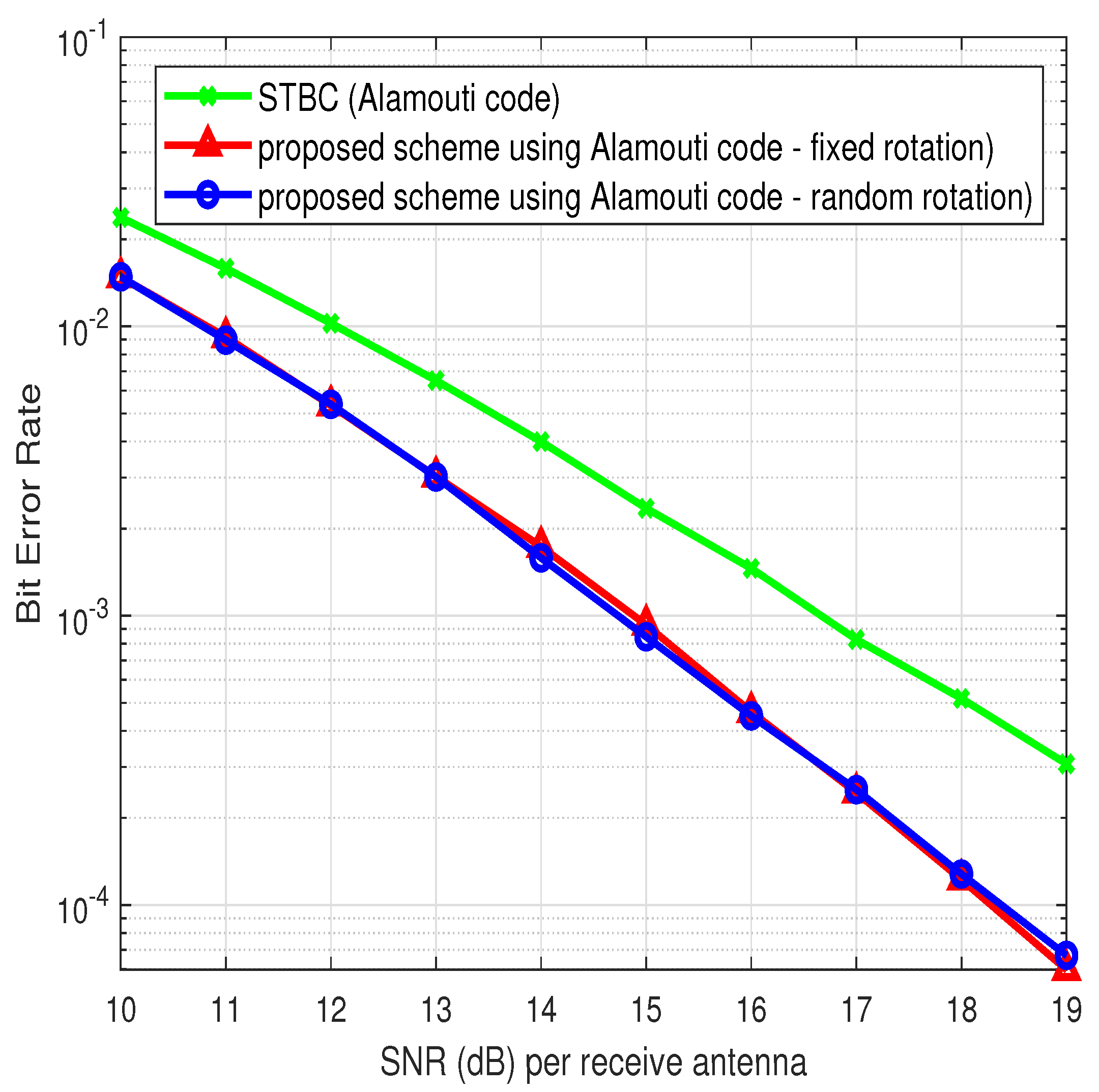
4. Simulation Results and Discussion

In all the simulations, the number of transmit antennas is either two ( M T = 2 ) or four ( M T = 4 ) and the receiver has perfect knowledge of the frequency-selective fading channel which contains uncorrelated and balanced taps with equal variance.
A.
Number of multipaths is two ( L = 2 )
In the first part of the simulation, L is assumed to be two and maximum-likelihood (ML) detection is employed at the receiver. QPSK space-time block coding (STBC) is considered and two streams ( M = 2 ) of Alamouti code are multiplexed based on our design. The block size K is therefore equal to 4. For random rotation, phases are randomly generated from [ 0 , 2 π ) . For deterministic rotation, according to Proposition 3, θ = 2 π / 11 is chosen because cos ( θ ) has a degree of 5. Figure 5 depicts the simulation results assuming M R = 1 . It also contains the performance result of the original Alamouti code in such channel. It is clear from the slope of the performance curves that the original Alamouti code exhibits inferior performance whereas our approach is able to utilize the original Alamouti code in the new design so as to exploit the frequency-diversity gain in addition to the spatial-diversity gain. In addition, random rotation and deterministic rotation show comparable performance as they both attain the maximum diversity gain.
Next, the number of transmit antenna increases to four and two streams of QPSK-modulated quasi-orthogonal space-time block code (QOSTBC) [32] designed for maximum space diversity in a flat fading channel are utilized. Figure 6 depicts the simulation results assuming M T = 4 , M R = 1 , L = 2 . As a comparison, the performance of original QOSTBC in the flat fading channel ( L = 1 ) with four transmit antennas is also shown. It is clear that the proposed scheme achieves better diversity gain, with an order of 4 × 2 = 8 , whereas the QOSTBC only achieves a diversity order of 4. We remark that the ML detection complexity of the proposed scheme is larger than that of QOSTBC, as the latter can exploit the property of QOSTBC to divide the detection task into two for separate groups of decodable symbols, which however can be performed only in a flat fading channel.
BPSK space-time trellis code (STTC) is then considered. The block size, K, is 130. The constituent STTC used in our scheme is the optimal 8-state BPSK STTC code designed for the flat fading M T = 2 channel (obtained by computer search in [33]), and has a generator matrix given by G 8 = [ 1110 ; 0101 ] T . Again, we consider multiplexing two streams of such STC, each one has a block size of 65 ( K = 65 · 2 = 130 ). For convenience, we name our scheme as Proposed- G 8 scheme. For deterministic rotation, θ = 2 π / 5 is chosen according to Proposition 2. Figure 7 and Figure 8 depict the simulation results, for M R = 1 and M R = 2 , respectively. Comparing with the original 8-state G 8 -STTC, the Proposed- G 8 scheme is superior since it is able to achieve full space-time-multipath diversity gain. We also compare our design with the best 8-state STTC ( G 8 = [ 1111 ; 1001 ] T ) previously found for the frequency-selective channel [23]. For both random and deterministic rotation, the Proposed- G 8 scheme outperforms the G 8 -STTC by around 1 dB at FER = 0.01 for M R = 1 . In terms of complexity, the Proposed- G 8 scheme however requires 128 ML states whereas the G 8 STTC requires only 16 ML states. Nonetheless, the simulations have validated our design that it attains the maximum diversity order by using simple space-time code designed for a flat fading channel.
B.
Number of multipaths is three ( L = 3 )
In the second part of the simulation, L is three, both M T and M R are two. The block size K is 132. First, BPSK modulation is considered. In Figure 9, the proposed scheme, Proposed- G 4 scheme, using a 4-state BPSK STTC (with generator G 4 = [ 011 ; 111 ] T ) and fixed rotation ( θ = 2 π / 5 ), is compared with one of the best 4-state STTCs (with generator G 4 = [ 111 ; 101 ] from [21]) designed for frequency-selective channels with 3 taps. Note that the Proposed- G 4 scheme requires 256 ML states whereas the G 4 -STTC requires 16 ML states only, and the performance of the Proposed- G 4 scheme outperforms G 4 -STTC by about 0.25 dB at FER = 0.01 . Both schemes deliver the maximum level of diversity performance as seen from the slope of the FER curves, therefore validating the diversity advantage of the proposed scheme for L = 3 . Next, in order to circumvent the complexity problem of ML detection, the iterative receiver as described in section III.C is used for the proposed scheme when the constituent STTC has a large number of states. Due to the suboptimal nature of the iterative receiver, the performance of the proposed scheme is compromised. Our focus is to assess its diversity performance over the range of desired FER as well as considering the comparison with existing space-time coding schemes of similar decoding complexity. As such, we remark that the major complexity requirement of the iterative receiver stems from the number of states required in the BCJR decoding algorithm rather than the linear FDE which has polynomial complexity and is independent of the STTC design. The proposed scheme, Proposed- G 16 , using the 16-state BPSK STTC (with generator G 16 = [ 11011 ; 01111 ] T ) from [34] is then considered. The rotation angle is fixed to θ = 2 π / 7 and its performance is shown in Figure 9. With a comparable number of states (16 states BCJR decoder), it offers a 1 dB gain over the G 4 -STTC (with 16 ML states) at FER = 0.01 while both schemes deliver the same level of diversity gain over the range of desired FER. Thus, it indicates that not only has the iterative receiver delivered the diversity advantage of the proposed scheme, it brings about a considerable amount of improvement over some STTC schemes. Hence, the proposed scheme using iterative receiver may yield good performance with affordable level of complexity.
Another comparison is also included in Figure 9, in which the performance of the best 16-state STTC ( G 16 = [ 11101 ; 11011 ] T ) [23] designed for frequency-selective channels is shown. It is slightly better than the Proposed- G 16 scheme but at the expense of larger number of ML states since it requires 64 ML states. Finally, Figure 9 shows the performance of the proposed scheme, Proposed- G 32 , with 32-state BPSK STTC (with generator G 32 = [ 110101 ; 101111 ] from [35]) and θ = 2 π / 7 . It outperforms the best 16-state G 16 -STTC code by about 1 dB at FER = 0.01 while requiring only 32 states in the BCJR decoder. Thus, the proposed scheme again yields promising performance with affordable level of complexity. Note that, as shown in Figure 9, the proposed scheme, Proposed- G 16 , is simulated for both random and fixed rotation, and they provide comparable performance when the iterative receiver is employed.
Next, QPSK modulation is considered. The proposed scheme, Proposed- G 32 , using the 32-state QPSK STTC (with generator G 32 = [ 2012122 ; 2201202 ] T from [36]) is considered. The rotation angle is chosen to be θ = 2 π / 19 and the iterative receiver is employed. In Figure 10, the result is compared to the best 4-state QPSK STTC code for frequency-selective fading channels (with G 4 = [ 12 ; 21 ] from [21]) and the gain of the proposed scheme is about 2 dB at FER = 0.01 while both schemes achieve equal diversity performance over the range of desired FER. In terms of the number of states in the decoder, Proposed- G 32 requires 32 states in the BCJR decoder whereas G 4 -STTC requires 64 ML states. Hence, it again indicates that the proposed scheme with iterative receiver is capable of outperforming the existing STTC scheme of comparable receiver complexity. The proposed scheme thus enables the use of any powerful STC among a large body of existing STC schemes designed for flat fading channels and transform it into effective STC for frequency-selective fading channels. Finally, as shown in Figure 10, the performance of using random rotation in the proposed scheme is as good as using deterministic rotation since both are able to extract the diversity gain inherent in the MIMO frequency-selective fading channel.

5. Conclusions

In this paper, a novel space-time coding approach is investigated for single-carrier transmission in a frequency-selective MIMO fading channel. By multiplexing independent streams of constituent space-time codes in a time-interleaved fashion followed by phase rotations, this new space-time code construction method is able to achieve full space-time-multipath diversity. It is also broadly applicable in the sense that, with proper rotations, it is potentially suitable for any number of transmit antennas or any type of modulation. It is shown that, both in theory and in simulations, the new scheme is a full-rate full-diversity scheme, while being flexible enough to incorporate any STC or MIMO scheme originally optimized for a flat fading channel as its constituent codes. Furthermore, iterative frequency domain equalization and decoding can be readily used for the new scheme to yield better performance than some of the best space-time codes designed for the frequency-selective fading channel with comparable receiver complexity.

Author Contributions

Conceptualization, B.K.N.; methodology, B.K.N. and C.-T.L.; validation, writing—original draft preparation, B.K.N.; writing—review and editing, C.-T.L. All authors have read and agreed to the published version of the manuscript.

Funding

This work was funded by the research funding of the Macao Polytechnic University, Macao SAR, China (Project no. RP/ESCA-02/2020).

Institutional Review Board Statement

Not applicable.

Informed Consent Statement

Not applicable.

Data Availability Statement

Not applicable.

Conflicts of Interest

The authors declare no conflict of interest.

Appendix A. Lemmas for Propositions 2 and 3

The following lemmas are required in the proofs of Propositions 2 and 3.
Lemma A1.
The determinant of B can be expressed as
det ( B ) = c 0 + c 1 e j θ + c 2 e j 2 θ + c ( M 1 ) M T e j ( M 1 ) M T θ .
Proof. 
The proof is an extension of the one used in Lemma 2 from [26]. In [26], the space-time thread traverses one row only for each column it visits whereas the thread in the proposed structure traverses a block of M T rows for each block of M T columns it visits (see Figure 3). Let σ be a permutation of the set ( 1 , 2 , , M M T ) . We decompose each permutation into M T partitions in such a way that the determinant (14) can be expressed as
det ( B ) = σ S K λ ( σ ) q = 1 M T p = 1 M b ( p 1 ) · M T + q , σ ( p 1 ) · M T + q .
That is, the q-th partition contains the rows ( p 1 ) · M T + q where p = 1 , , M .
Let ϕ = e j θ and denote exp ϕ ( b i , j ) as the operator which returns the exponent of ϕ in b i , j (e.g., if b i , j = e j 2 θ , then exp ϕ ( b i , j ) = 2 ). Due to the thread structure of B , we have
exp ϕ ( b k j M · M T + q 1 , ( k 1 ) · M T + q 2 ) = j 1 M q 1 , q 2 { 1 , , M T }
where j , k { 1 , , M } . It can then be shown that
M exp ϕ ( b ( j 1 1 ) · M T + q 1 , ( k 0 1 ) · M T + q 2 ) M exp ϕ ( b ( j 2 1 ) · M T + q 3 , ( k 0 1 ) · M T + q 4 ) M = j 2 j 1 q 1 , q 2 , q 3 , q 4 { 1 , , M T }
where j 2 > j 1 , j 1 , j 2 { 1 , , M } and k 0 { 1 , , M } . Note that the above relationship holds despite the values of q 1 , q 2 , q 3 , q 4 . Furthermore, the sum of the exponents over any row or any combinations of rows within the r-th block of rows can be expressed as
q = 1 M T p = 1 M exp ϕ ( b f r ( p , q ) , σ ( p 1 ) M T + q ) = M T ( M 1 ) 2
where f r ( p , q ) is any function of p , q such that ( r 1 ) M T + 1 f ( p , q ) r M T . Next, for one permutation σ , the sum of exponents can be expressed as
M exp ϕ ( σ ) M = M exp ϕ q = 1 M T p = 1 M b ( p 1 ) M T + q , σ ( p 1 ) M T + q M = M q = 1 M T p = 1 M exp ϕ ( b ( p 1 ) M T + q , σ ( p 1 ) M T + q ) M = M q = 1 M T p = 1 M 1 exp ϕ ( b ( p 1 ) M T + q , σ ( p 1 ) M T + q ) + = exp ϕ ( b ( M 1 ) M T + q , σ ( M 1 ) M T + q ) M .
The last term in the above equation can be expressed as the sum of the exponents of the whole row subtracting the remaining entries in the same row and gives
exp ϕ ( b ( M 1 ) M T + q , σ ( M 1 ) M T + q ) = M T ( M 1 ) 2 p = 1 M 1 exp ϕ ( b ( M 1 ) M T + q , σ ( p 1 ) M T + q ) p = 1 M q q exp ϕ ( b ( M 1 ) M T + q , σ ( p 1 ) M T + q ) .
The above equation is substituted into (A6) and then one of the summations in (A6) gives
q = 1 M T p = 1 M q q exp ϕ ( b ( M 1 ) M T + q , σ ( p 1 ) M T + q ) = q = 1 M T p = 1 M q = 1 M T exp ϕ ( b ( M 1 ) M T + q , σ ( p 1 ) M T + q ) exp ϕ ( b ( M 1 ) M T + q , σ ( p 1 ) M T + q ) = q = 1 M T M T ( M 1 ) 2 M T ( M 1 ) 2 = M T ( M T 1 ) ( M 1 ) 2
where we have used the relationship of (A5). Using (A5), (A8) and a M + b M M = a + b M , (A6) can be shown as
M exp ϕ ( σ ) M = M ( M 1 ) M T ( 3 M T ) 2 M .
Therefore, since M T is an integer, exp ϕ ( σ ) is always an integer. The determinant B (A1) can thus be expressed as a summation of terms, each of which contains an exponential with integer multiples of the angle θ . The largest angle, ( M 1 ) M T , is due to the permutations traversing only the Mth-thread (in which exp ϕ ( b i , j ) = M 1 / M ) because they are the only permutations that yield the maximum angle. □
Lemma A2
(see [26]). If α 1 , , α m are distinct algebraic numbers, and if c 1 , , c m are algebraic numbers not all equal to zero, then
l = 1 m c l e α l 0 .
Furthermore, if α is an algebraic number ≠ 0, then e α is transcendental.

Appendix B. Frequency Domain Iterative Receiver

The detailed formulation of the frequency domain iterative receiver applicable to the proposed rotation-interleaved multi-stream space-time code is described as follows. The iterative receiver consists of the soft-cancellation, MMSE frequency domain equalization (MMSE-FDE) and the decoding.
The MMSE-FDE aims to find the estimates of the input coded symbols transmitted from antenna i { 1 , , M T } . Recall that K denotes the size of transmitted block. Denote O i j as the channel matrix corresponding to the ( i , j ) th transmit-receive antenna pair and O i j C K × K is a circulant matrix with [ h i j ( 0 ) , h i j ( 1 ) , , h i j ( L 1 ) , 0 , , 0 ] as its first row. By performing the eigen-decomposition, O i j can be written as O i j = F H Γ i j F , where F is the FFT-matrix and Γ i j is a diagonal matrix containing the channel coefficients in the frequency domain. Denote Ξ i = [ Γ i 1 H , , Γ i M R H ] H and Ω = [ Ξ 1 , , Ξ M T ] . The MMSE-FDE will take into consideration the quality of the soft-cancellation, which is explained as follows. Let us denote s ¯ t i as the soft estimation of s t i , the transmitted symbol from the ith antenna at time t, which is obtained from the decoding process in the last iteration, and the estimates are assumed to be s ¯ t i E [ s t i | Y ] . Then, the covariance matrix of estimation error can be approximated by Λ t = d i a g ( E s | s ¯ t 1 | 2 , E s | s ¯ t 2 | 2 , , E s | s ¯ t M T | 2 ) . To further simplify the computation of the MMSE filter coefficients, we calculate the average of the estimation error as ϱ = 1 / ( K M T ) t = 1 K i = 1 M T | s t i | 2 and therefore Λ t ϱ I M T . Denote the frequency domain representation of the received signal vector at receive antenna j as r ̲ j = F ( y j ) T and r ̲ = [ r ̲ 1 H , , r ̲ M R H ] H . In addition, denote s ¯ i = [ s ¯ 1 i , , s ¯ K i ] T and its frequency domain representation as s ¯ ̲ i = F s ¯ i . Then, denote r ¯ ̲ = Ω [ ( s ¯ ̲ 1 ) H , , ( s ¯ ̲ M T ) H ] H . Define Ψ = Ω Λ Ω H + σ 2 I K M R × K M T , where Λ = ( E s ϱ ) I K M R × K M T , and γ i = ( 1 / K ) T r ( Ξ i H Ψ Ξ i ) . Then, the outputs from the MMSE-FDE can be expressed as [29]
z i = γ i 1 F H Ξ i H Ψ 1 ( r ̲ r ¯ ̲ ) + s ¯ ̲ i .
Equivalently, with the AWGN channel assumption, the output, the tth entry in z i , can be written in the form
z t i = s t i + ν t i
where ν t i is modeled as zero-mean circularly-symmetric Gaussian distributed with variance given by
σ ν , i , t 2 = γ i 1 ( E s ϱ ) .
The extrinsic LLRs, which are subsequently fed to the decoder as intrinsic LLRs, can be derived by using the equivalent output form (1) and the bits-to-symbol mapping. If BPSK is used, the extrinsic LLR sequences of the code bits are simply given by
λ e [ c t i ] = 4 R e { e j θ t i z t i } γ i 1 ( E s ϱ )
where c t i and θ t i are the transmitted code bit and the respective rotation applied at time t on ith antenna, respectively. Note that c t i and θ t i belong to a particular stream and we drop the stream index for simplicity.
During the decoding process, binary code decoders such as BCJR decoders can be used to return the extrinsic LLRs of the code bits, denoted as λ e c [ c t i ] , which will then be used to generate the soft estimates:
c ¯ t i = t a n h 1 2 λ e c [ c t i ] .
The soft estimates of the transmitted symbols via the bits-to-symbol mapping followed by the respective rotation can be generated and fed to the MMSE-FDE described above.

References

  1. Xu, C.; Ishikawa, N.; Rajashekar, R.; Sugiura, S.; Maunder, R.G.; Wang, Z.; Yang, L.-L.; Hanzo, L. Sixty Years of Coherent Versus Non-Coherent Tradeoffs and the Road From 5G to Wireless Futures. IEEE Access 2019, 7, 178246–178299. [Google Scholar] [CrossRef]
  2. Tarokh, V.; Jafarkhani, H.; Calderbank, A. Space-time block codes from orthogonal designs. IEEE Trans. Inf. Theory 1999, 45, 1456–1467. [Google Scholar] [CrossRef]
  3. Gamal, H.E.; Harnmons, A.R. On the design and performance of algebraic space-time codes for BPSK and QPSK modulation. IEEE Trans. Commun. 2002, 50, 907–913. [Google Scholar] [CrossRef]
  4. De Almeida, A.L.; Antreich, F.; Haardt, M.; Cavalcante, C.C. Kronecker product-based space-time block codes. IEEE Wirel. Commun. Lett. 2022, 11, 386–390. [Google Scholar]
  5. Grabner, M.J.; Li, X.; Fu, S. An adaptive BLAST successive interference cancellation method for high data rate perfect space-time coded MIMO systems. IEEE Trans. Veh. Technol. 2020, 69, 15421553. [Google Scholar] [CrossRef]
  6. Feng, B.; Jiao, J.; Wang, S.; Wu, S.; Zhang, Q. Construction of polar codes concatenated to space-time block coding in MIMO system. In Proceedings of the 2016 IEEE 84th Vehicular Technology Conference (VTC-Fall), Montreal, QC, Canada, 18–21 September 2016. [Google Scholar]
  7. Tofigh, S.; Kermani, H.M.; Morsali, A. A new design criterion for linear receivers STBCs based on full-rank spaces. EEE Commun. Lett. 2014, 19, 207–210. [Google Scholar] [CrossRef]
  8. Harshan, J.; Viterbo, E. Integer space-time block codes for practical MIMO systems. IEEE Wirel. Commun. Lett. 2013, 2, 455–458. [Google Scholar] [CrossRef] [Green Version]
  9. Mroueh, L.; Rouquette-Leveil, S.; Belfiore, J.C. Application of perfect space time codes: PEP bounds and some practical insights. IEEE Trans. Commun. 2012, 60, 747–755. [Google Scholar] [CrossRef]
  10. Xu, C.; Zhang, P.; Rajashekar, R.; Ishikawa, N.; Sugiura, S.; Wang, L.; Hanzo, L. Finite-Cardinality Single-RF Differential Space-Time Modulation for Improving the Diversity-Throughput Tradeoff. IEEE Trans. Commun. 2018, 67, 318–335. [Google Scholar] [CrossRef]
  11. Agrawal, D.; Tarokh, V.; Naguib, A.; Seshadri, N. Space-time coded OFDM for high data-rate wireless communication over wideband channels. In Proceedings of the 48th IEEE Vehicular Technology Conference (VTC ’98), Ottawa, ON, Canada, 21 May 1998; Volume 3, pp. 2232–2236. [Google Scholar]
  12. Liu, Z.; Xin, Y.; Giannakis, G. Space-time-frequency coded OFDM over frequency-selective fading channels. IEEE Trans. Signal Process. 2002, 50, 2465–2476. [Google Scholar]
  13. Yeh, H.-G. Design precoded space-time-frequency 4 × 1 and 4 × 2 OFDM architectures in frequency-selective fading channels. IEEE Syst. J. 2019, 14, 277–287. [Google Scholar] [CrossRef]
  14. Ma, X.; Giannakis, G.B. Space-time-multipath coding using digital phase sweeping. In Proceedings of the Global Telecommunications Conference (GLOBECOM ’02), Taipei, Taiwan, 17–21 November 2002; Volume 1, pp. 384–388. [Google Scholar]
  15. Mohammadian, Z.; Shahabinejad, M.; Talebi, S. New Full-Diversity Space-Frequency Block Codes Based on the OSTBCs. IEEE Commun. Lett. 2012, 16, 1620–1623. [Google Scholar] [CrossRef]
  16. Flores, J.; Sanchez, J.; Jafarkhani, H. Quasi-orthogonal space-time-frequency trellis codes for two transmit antennas. IEEE Trans. Wirel. Commun. 2010, 9, 2125–2129. [Google Scholar] [CrossRef]
  17. Gore, D.; Sandhu, S.; Paulraj, A. Delay diversity codes for frequency selective channels. In Proceedings of the 2002 IEEE International Conference on Communications, New York, NY, USA, 28 April–2 May 2002; Volume 3, pp. 1949–1953. [Google Scholar]
  18. Liu, Y.; Fitz, M.P.; Takeshita, O.Y. Space-time codes performance criteria and design for frequency selective fading channels. In Proceedings of the IEEE International Conference on Communications (ICC 2001), Helsinki, Finland, 11–14 June 2001; Volume 9, pp. 2800–2804. [Google Scholar]
  19. Al-Dhahir, N. Single-carrier frequency-domain equalization for space-time block-coded transmissions over frequency-selective fading channels. IEEE Commun. Lett. 2001, 5, 304–306. [Google Scholar] [CrossRef]
  20. Zhou, S.; Giannakis, G.B. Single-carrier space-time block-coded transmissions over frequency-selective fading channels. IEEE Trans. Inform. Theory 2003, 49, 164–179. [Google Scholar] [CrossRef]
  21. Gamal, H.E.; Hammons, A.R.H., Jr.; Liu, Y.; Fitz, M.P.; Takeshita, O.Y. On the design of space-time and space-frequency codes for MIMO frequency-selective fading channels. IEEE Trans. Inform. Theory 2003, 49, 2277–2292. [Google Scholar] [CrossRef] [Green Version]
  22. Ciochina, C.; Castelain, D.; Mottier, D.; Sari, H. A Novel Quasi-Orthogonal Space-Frequency Block Code for Single-Carrier FDMA. In Proceedings of the VTC Spring 2008—IEEE Vehicular Technology Conference, Singapore, 11–14 May 2008; pp. 1137–1141. [Google Scholar]
  23. Qin, M.; Blum, R.S. Properties of space-time codes for frequency-selective channels. IEEE Trans. Signal Process. 2004, 52, 694–702. [Google Scholar] [CrossRef]
  24. Kansanen, K.; Matsumoto, T. An analytical method for MMSE MIMO turbo equalizer EXIT chart computation. IEEE Trans. Wirel. Commun. 2007, 6, 59–63. [Google Scholar] [CrossRef]
  25. Ng, B.K.; Lam, C.T. Single-carrier time-interleaved space-time code for frequency-selective fading channels. In Proceedings of the 2014 IEEE 8th Sensor Array and Multichannel Signal Processing Workshop (SAM), A Coruna, Spain, 22–25 June 2014. [Google Scholar]
  26. Gamal, H.E.; Damen, M.O. Universal space-time coding. IEEE Trans. Inf. Theory 2003, 49, 1097–1118. [Google Scholar] [CrossRef] [Green Version]
  27. Giraud, X.; Boutillon, E.; Belfiore, J.-C. Algebraic tools to build modulation schemes for fading channels. IEEE Trans. Inform. Theory 1997, 43, 938–952. [Google Scholar] [CrossRef]
  28. Damen, M.O. Joint Coding/Decoding in a Multiple Access System, Application to Mobile Communications. Ph.D. Thesis, ENST, Paris, France, 1999. [Google Scholar]
  29. Gromann, M. Transmission Strategies for Broadband Systems with MMSE Turbo Equalization. Ph.D. Thesis, Ilmenau University of Technology, Ilmenau, Germany, 2012. [Google Scholar]
  30. Trofimov, A.; Johansson, T. A memory-efficient optimal APP symbol-decoding algorithm for linear block codes. IEEE Trans. Commun. 2004, 52, 1429–1434. [Google Scholar] [CrossRef]
  31. Shrestha, R.; Paily, R.P. High-Throughput Turbo Decoder With Parallel Architecture for LTE Wireless Communication Standards. IEEE Trans. Circuits Syst. Regul. Pap. 2014, 61, 2699–2710. [Google Scholar] [CrossRef]
  32. Su, W.; Xia, X.G. Signal constellations for quasi-orthogonal space-time block codes with full diversity. IEEE Trans. Inf. Theory 2004, 50, 2331–2347. [Google Scholar]
  33. Grimm, J.; Fitz, M.P.; Krogmeier, J.V. Further results on space-time coding for Rayleigh fadin. In Proceedings of the Annual Allerton Conference on Communication Control and Computing, Monticello, IL, USA, 23–26 September 1998; pp. 391–400. [Google Scholar]
  34. Yan, Q.; Blum, R.S. Improved space-time convolutional codes for quasi-static slow fading channels. IEEE Trans. Wirel. Commun. 2002, 1, 563–571. [Google Scholar]
  35. Hammons, A.R.; Gamal, H.E. On the theory of space-time codes for PSK modulation. IEEE Trans. Inf. Theory 2000, 46, 524–542. [Google Scholar] [CrossRef] [Green Version]
  36. Hong, Y.; i Fabregas, A.G. New space-time trellis codes for two-antenna quasi-static channels. IEEE Trans. Veh. Technol. 2007, 56, 3581–3587. [Google Scholar] [CrossRef]
Figure 1. Proposed method.
Applsci 12 12803 g001
Figure 2. The time-interleaved multiplexer of rotated streams ( L = 3 , M = 3 , M T = 2 ).
Applsci 12 12803 g002
Figure 3. The block-based space-time threading structure ( M = L = 4 ).
Applsci 12 12803 g003
Figure 4. Iterative receiver based on linear MMSE-FDE and turbo processing.
Applsci 12 12803 g004
Figure 5. Performance of the proposed scheme based on QPSK—modulated STBC, M T = 2 , M R = 1 , L = M = 2 .
Applsci 12 12803 g005
Figure 6. Performance of the proposed scheme based on QPSK—modulated STBC, M T = 4 , M R = 1 , L = M = 2 .
Applsci 12 12803 g006
Figure 7. Performance of the proposed scheme based on BPSK—modulated STTC, M T = 2 , M R = 1 , L = M = 2 .
Applsci 12 12803 g007
Figure 8. Performance of the proposed scheme based on BPSK—modulated STTC, M T = 2 , M R = 2 , L = M = 2 .
Applsci 12 12803 g008
Figure 9. Performance of the proposed scheme based on BPSK—modulated STTC, M T = 2 , M R = 2 , L = M = 3 .
Applsci 12 12803 g009
Figure 10. Performance of the proposed scheme based on QPSK—modulated STTC, M T = 2 , M R = 2 , L = M = 3 .
Applsci 12 12803 g010
Table 1. Comparison of Single-carrier Space-time Codes for Frequency-Selective Fading Channel ( 1 Specific means that the scheme may require further numerical searches/verification to find the codewords for other types of modulations (or different number of Tx antennas) not shown in their present work).
Schemes[17][19][20][21][22][23]
ModulationAnyAnyAnySpecific 1 AnySpecific
No. of Tx AntennasAnyAnyAnySpecificFixedSpecific
Full-Rate×××
Full space-time-multipath diversity
Numerical Search/Verification××××
Publisher’s Note: MDPI stays neutral with regard to jurisdictional claims in published maps and institutional affiliations.

