
Transmission Removal from a Single Glass Scene and Its Application in Photographer Identification


Abstract
1. Introduction
- We propose a transmission removal network to recover the reflection layer from the mixture image. In order to recover the weaker components from the mixture image, the edge and color distribution of transmission layer is introduced as a prior to guide the reflection layer separation. In a practical application scenario, we can replace the real transmission layer with a predicted one through reflection removal.
- By analyzing the performance exhibited at different levels of the feature maps, we improve the generated results in different dimensions such as resolution, texture, and style to enhance the visual perception of the estimated reflection layer. We also use PatchGAN as the discriminator to enhance the perceptual strength of the generated image and ground truth.
- We consider the portrait’s appearance in the reflection layer as a separate problem and improve the style loss to solve the problem of the dim portrait in the reflection layer. Thus, the reflection layer image can be effectively applied to photographer identification application.
2. Related Works
2.1. Reflection Removal
2.2. Transmission Removal
3. Proposed Method
3.1. Input Preprocessing
3.2. Network Architecture
3.3. Loss Function
3.3.1. Adversarial Loss
3.3.2. Global Loss
3.3.3. Patch-Level Loss
Exclusion Loss
Style Loss
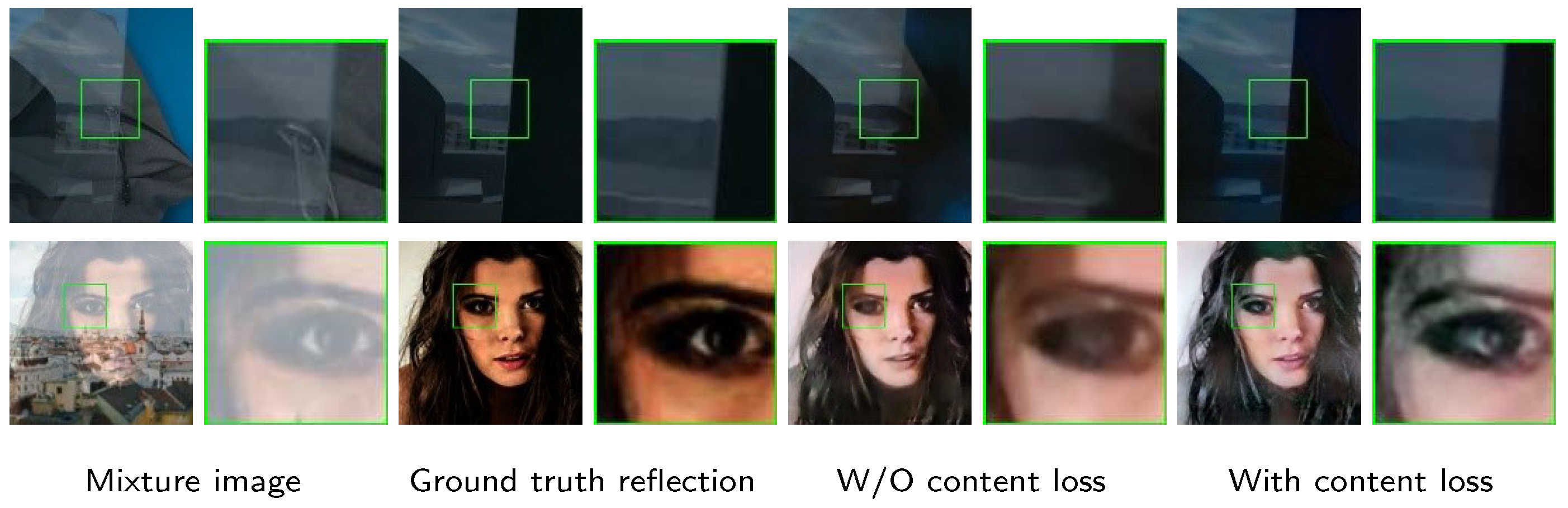
Content Loss
3.4. Application to Photographer Identification
4. Results
4.1. Experiment Preparation
4.1.1. Comparative Methods
4.1.2. Evaluation Metrics
4.1.3. Datasets
Existing Dataset
- (1)
- The reflection removal method proposed in Wan et al. [41] provides a reasonable way to obtain the ground truth for the reflection component image. In detail, by putting a piece of black cloth behind the glass, only the camera can capture the reflection light reflected by the glass. The dataset (Downloaded from https://sir2data.github.io, accessed on 29 July 2022) in [41] has 500 real-world triplets.
- (2)
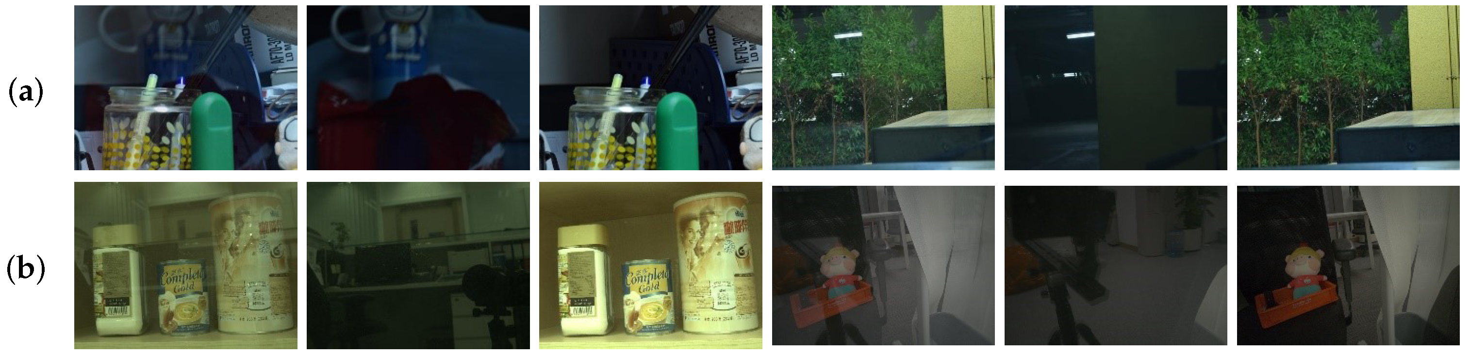
- Recently, Lei et al. [13] proposed a method to obtain a pure flash transmission layer with no reflection. The article minimizes the effect of the reflection layer by combining the image before and after the flash. After preprocessing the image, the triplet image can be obtained as the dataset (Downloaded from https://hkustconnect-my.sharepoint.com/personal/cleiaa_connect_ust_hk/Documents/Projects/cvpr2021-flash-rr/data.zip?ga=1, accessed on 29 July 2022). Their dataset consists of 4056 triplet images for training and 1012 triplet images for validation, both synthetic and real-world. Note that this dataset contains 35 triplet images from [41], so we eliminate them to obtain 4021 training triplet images. Some examples from the existing datasets are shown in Figure 7.
Synthetic Data Generation
4.1.4. Implementation and Training Details
4.2. Transmission Removal Results for General Scenarios
4.3. Ablation Study
4.4. Transmission Removal for Photographer Identification
5. Conclusions
Author Contributions
Funding
Institutional Review Board Statement
Informed Consent Statement
Data Availability Statement
Acknowledgments
Conflicts of Interest
References
- Medhi, J.P.; Nirmala, S.; Choudhury, S.; Dandapat, S. Improved detection and analysis of Macular Edema using modified guided image filtering with modified level set spatial fuzzy clustering on Optical Coherence Tomography images. Biomed. Signal Process. Control 2023, 79, 104149. [Google Scholar] [CrossRef]
- Hilal, A.; Alabdulkreem, E.; Alzahrani, J.; Eltahir, M.; Eldesouki, M.; Yaseen, I.; Motwakel, A.; Marzouk, R.; Mustafa, A. Political optimizer with deep learning-enabled tongue color image analysis model. Comput. Syst. Sci. Eng. 2023, 45, 1129–1143. [Google Scholar] [CrossRef]
- Ibrahim, H.; Fahmy, O.M.; Elattar, M.A. License plate Image analysis empowered by Generative Adversarial Neural Networks (GANs). IEEE Access 2022, 10, 30846–30857. [Google Scholar]
- Kubicek, J.; Penhaker, M.; Krejcar, O.; Selamat, A. Modern trends and Applications of Intelligent methods in Biomedical signal and Image processing. Sensors 2021, 21, 847. [Google Scholar] [CrossRef] [PubMed]
- Mambou, S.; Krejcar, O.; Selamat, A.; Dobrovolny, M.; Maresova, P.; Kuca, K. Novel thermal image classification based on techniques derived from mathematical morphology: Case of breast cancer. In Proceedings of the International Work-Conference on Bioinformatics and Biomedical Engineering, Granada, Spain, 6–8 May 2020; pp. 683–694. [Google Scholar]
- Rezaei, Z.; Selamat, A.; Taki, A.; Rahim, M.S.M.; Kadir, M.R.A. Automatic plaque segmentation based on hybrid fuzzy clustering and k nearest neighborhood using virtual histology intravascular ultrasound images. Appl. Soft Comput. 2017, 53, 380–395. [Google Scholar] [CrossRef]
- Bach, H.; Neuroth, N. The Properties of Optical Glass; Springer Science & Business Media: Berlin/Heidelberg, Germany, 1998. [Google Scholar]
- Isola, P.; Zhu, J.Y.; Zhou, T.; Efros, A.A. Image-to-image translation with conditional adversarial networks. In Proceedings of the IEEE/CVF Conference on Computer Vision and Pattern Recognition, Honolulu, HI, USA, 21–26 July 2017; pp. 1125–1134. [Google Scholar]
- Li, Y.; Yan, Q.; Zhang, K.; Xu, H. Image Reflection Removal via Contextual Feature Fusion Pyramid and Task-Driven Regularization. IEEE Trans. Circuits Syst. Video Technol. 2022, 32, 553–565. [Google Scholar] [CrossRef]
- Zhang, X.; Ng, R.; Chen, Q. Single image reflection separation with perceptual losses. In Proceedings of the IEEE/CVF Conference on Computer Vision and Pattern Recognition, Salt Lake City, UT, USA, 18–22 June 2018; pp. 4786–4794. [Google Scholar]
- Wan, R.; Shi, B.; Duan, L.Y.; Tan, A.H.; Kot, A.C. CRRN: Multi-scale guided concurrent reflection removal network. In Proceedings of the IEEE/CVF Conference on Computer Vision and Pattern Recognition, Salt Lake City, UT, USA, 18–22 June 2018; pp. 4777–4785. [Google Scholar]
- Wan, R.; Shi, B.; Li, H.; Duan, L.Y.; Tan, A.H.; Kot, A.C. CoRRN: Cooperative reflection removal network. IEEE Trans. Pattern Anal. Mach. Intell. 2019, 42, 2969–2982. [Google Scholar] [CrossRef]
- Lei, C.; Chen, Q. Robust reflection removal with reflection-free flash-only cues. In Proceedings of the IEEE/CVF Conference on Computer Vision and Pattern Recognition, Nashville, TN, USA, 20–25 June 2021; pp. 14811–14820. [Google Scholar]
- Li, Y.; Brown, M.S. Single image layer separation using relative smoothness. In Proceedings of the IEEE/CVF Conference on Computer Vision and Pattern Recognition, Columbus, OH, USA, 23–28 June 2014; pp. 2752–2759. [Google Scholar]
- Yang, J.; Gong, D.; Liu, L.; Shi, Q. Seeing deeply and bidirectionally: A deep learning approach for single image reflection removal. In Proceedings of the European Conference on Computer Vision, Munich, Germany, 8–14 September 2018; pp. 654–669. [Google Scholar]
- Chang, Y.C.; Lu, C.N.; Cheng, C.C.; Chiu, W.C. Single image reflection removal with edge guidance, reflection classifier, and recurrent decomposition. In Proceedings of the IEEE/CVF Winter Conference on Applications of Computer Vision, Virtual Conference, 5–9 January 2021; pp. 2033–2042. [Google Scholar]
- Li, C.; Yang, Y.; He, K.; Lin, S.; Hopcroft, J.E. Single image reflection removal through cascaded refinement. In Proceedings of the IEEE/CVF Conference on Computer Vision and Pattern Recognition, Seattle, WA, USA, 14–19 June 2020; pp. 3565–3574. [Google Scholar]
- Song, B.; Zhou, J.; Wu, H. Multi-stage Curvature-guided Network for Progressive Single Image Reflection Removal. IEEE Trans. Circuits Syst. Video Technol. 2022, 32, 6515–6529. [Google Scholar] [CrossRef]
- Fan, Q.; Yang, J.; Hua, G.; Chen, B.; Wipf, D. A generic deep architecture for single image reflection removal and image smoothing. In Proceedings of the IEEE International Conference on Computer Vision, Venice, Italy, 22–29 October 2017; pp. 3238–3247. [Google Scholar]
- Wan, R.; Shi, B.; Li, H.; Duan, L.Y.; Kot, A.C. Reflection scene separation from a single image. In Proceedings of the IEEE/CVF Conference on Computer Vision and Pattern Recognition, Seattle, WA, USA, 14–19 June 2020; pp. 2398–2406. [Google Scholar]
- Wan, R.; Shi, B.; Hwee, T.A.; Kot, A.C. Depth of field guided reflection removal. In Proceedings of the IEEE International Conference on Image Processing, Phoenix, AZ, USA, 25–28 September 2016; pp. 21–25. [Google Scholar]
- Springer, O.; Weiss, Y. Reflection separation using guided annotation. In Proceedings of the IEEE International Conference on Image Processing, Beijing, China, 17–20 September 2017; pp. 1192–1196. [Google Scholar]
- Arvanitopoulos, N.; Achanta, R.; Susstrunk, S. Single image reflection suppression. In Proceedings of the IEEE/CVF Conference on Computer Vision and Pattern Recognition, Honolulu, HI, USA, 21–26 July 2017; pp. 4498–4506. [Google Scholar]
- Levin, A.; Weiss, Y. User assisted separation of reflections from a single image using a sparsity prior. IEEE Trans. Pattern Anal. Mach. Intell. 2007, 29, 1647–1654. [Google Scholar] [CrossRef] [PubMed]
- Mechrez, R.; Talmi, I.; Shama, F.; Zelnik-Manor, L. Maintaining natural image statistics with the contextual loss. In Proceedings of the Asian Conference on Computer Vision, Perth, Australia, 2–6 December 2018; pp. 427–443. [Google Scholar]
- Yano, T.; Shimizu, M.; Okutomi, M. Image restoration and disparity estimation from an uncalibrated multi-layered image. In Proceedings of the IEEE/CVF Conference on Computer Vision and Pattern Recognition, San Francisco, CA, USA, 13–18 June 2010; pp. 247–254. [Google Scholar]
- Rafiq, M.; Bajwa, U.I.; Gilanie, G.; Anwar, W. Reconstruction of scene using corneal reflection. Multimed. Tools Appl. 2021, 80, 21363–21379. [Google Scholar] [CrossRef]
- Jenkins, R.; Kerr, C. Identifiable images of bystanders extracted from corneal reflections. PLoS ONE 2013, 8, e83325. [Google Scholar] [CrossRef] [PubMed]
- Wu, J.; Ji, Z. Seeing the unseen: Locating objects from reflections. In Proceedings of the Annual conference towards autonomous robotic systems, Bristol, UK, 25–27 July 2018; pp. 221–233. [Google Scholar]
- Nishino, K.; Nayar, S.K. Eyes for relighting. ACM Trans. Graph. 2004, 23, 704–711. [Google Scholar] [CrossRef]
- Nishino, K.; Belhumeur, P.N.; Nayar, S.K. Using eye reflections for face recognition under varying illumination. In Proceedings of the IEEE International Conference on Computer Vision, Beijing, China, 17–20 October 2005; pp. 519–526. [Google Scholar]
- Wen, Q.; Tan, Y.; Qin, J.; Liu, W.; Han, G.; He, S. Single image reflection removal beyond linearity. In Proceedings of the IEEE/CVF Conference on Computer Vision and Pattern Recognition, Long Beach, CA, USA, 15–20 June 2019; pp. 3771–3779. [Google Scholar]
- Zhang, K.; Sun, M.; Han, T.X.; Yuan, X.; Guo, L.; Liu, T. Residual Networks of Residual Networks: Multilevel Residual Networks. IEEE Trans. Circuits Syst. Video Technol. 2018, 28, 1303–1314. [Google Scholar] [CrossRef]
- Wang, Y.; Wang, L.; Wang, H.; Li, P. Resolution-Aware Network for Image Super-Resolution. IEEE Trans. Circuits Syst. Video Technol. 2019, 29, 1259–1269. [Google Scholar] [CrossRef]
- Xiang, X.; Zhu, L.; Li, J.; Wang, Y.; Huang, T.; Tian, Y. Learning Super-Resolution Reconstruction for High Temporal Resolution Spike Stream. IEEE Trans. Circuits Syst. Video Technol. 2021. [Google Scholar] [CrossRef]
- Dong, C.; Loy, C.C.; He, K.; Tang, X. Learning a deep convolutional network for image super-resolution. In Proceedings of the European Conference on Computer Vision, Zurich, Switzerland, 6–12 September 2014; pp. 184–199. [Google Scholar]
- Gatys, L.A.; Ecker, A.S.; Bethge, M. Image style transfer using convolutional neural networks. In Proceedings of the IEEE/CVF Conference on Computer Vision and Pattern Recognition, Las Vegas, NV, USA, 27–30 June 2016; pp. 2414–2423. [Google Scholar]
- Li, C.; Wand, M. Combining markov random fields and convolutional neural networks for image synthesis. In Proceedings of the IEEE/CVF Conference on Computer Vision and Pattern Recognition, Las Vegas, NV, USA, 27–30 June 2016; pp. 2479–2486. [Google Scholar]
- Johnson, J.; Alahi, A.; Li, F.F. Perceptual Losses for Real-Time Style Transfer and Super-Resolution. In Proceedings of the European Conference on Computer Vision, Amsterdam, The Netherlands, 11–14 October 2016; pp. 694–711. [Google Scholar]
- Zhang, R.; Isola, P.; Efros, A.A.; Shechtman, E.; Wang, O. The unreasonable effectiveness of deep features as a perceptual metric. In Proceedings of the IEEE/CVF Conference on Computer Vision and Pattern Recognition, Salt Lake City, UT, USA, 18–22 June 2018; pp. 586–595. [Google Scholar]
- Wan, R.; Shi, B.; Duan, L.Y.; Tan, A.H.; Kot, A.C. Benchmarking single-image reflection removal algorithms. In Proceedings of the IEEE International Conference on Computer Vision, Venice, Italy, 22–29 October 2017; pp. 3922–3930. [Google Scholar]
- Guo, C.; Li, C.; Guo, J.; Loy, C.C.; Hou, J.; Kwong, S.; Cong, R. Zero-reference deep curve estimation for low-light image enhancement. In Proceedings of the IEEE/CVF Conference on Computer Vision and Pattern Recognition, Seattle, WA, USA, 14–19 June 2020; pp. 1780–1789. [Google Scholar]
- Fu, Y.; Hong, Y.; Chen, L.; You, S. LE-GAN: Unsupervised low-light image enhancement network using attention module and identity invariant loss. Knowl.-Based Syst. 2022, 240, 108010. [Google Scholar] [CrossRef]
- Serengil, S.I.; Ozpinar, A. Lightface: A hybrid deep face recognition framework. In Proceedings of the Innovations in Intelligent Systems and Applications Conference (ASYU), Istanbul, Turkey, 15–17 October 2020; pp. 1–5. [Google Scholar]
- Chen, B.C.; Chen, C.S.; Hsu, W.H. Cross-age reference coding for age-invariant face recognition and retrieval. In Proceedings of the European Conference on Computer Vision, Zurich, Switzerland, 6–12 September 2014; pp. 768–783. [Google Scholar]


| Method | Publication | Main Technical Route | TECR | TRCR |
|---|---|---|---|---|
| Wan et al. [11] | CVPR2019 | Multi-scale edge guidance model | Yes | No |
| Zhang et al. [10] | CVPR2018 | Dilated convolution model and exclusion loss | Yes | No |
| Yang et al. [15] | ECCV2019 | Bi-directional estimation model | Yes | No |
| Li et al. [14] | CVPR2015 | Distribution-based traditional model | Yes | N/A |
| Lei et al. [13] | CVPR2021 | Free reflection cue guidance model | Yes | Yes |
| Chang et al. [16] | WACV2021 | Edge guidance and recurrent decomposition model | Yes | Yes |
| Li et al. [17] | CVPR2020 | Cascade network with LSTM module and reconstruction loss | Yes | Yes |
| Wan et al. [20] | CVPR2020 | Dilated convolution model, U-Net, and shift-invariant loss | No | No |
| LPIPS (↓) | SSIM (↑) | PSNR (dB) (↑) | |
|---|---|---|---|
| Wan et al. [11] | -/0.512 | -/0.716 | -/21.934 |
| Zhang et al. [10]/ Wan et al. [20] | -/0.578 | -/0.723 | -/23.581 |
| Yang et al. [15] | -/0.635 | -/0.420 | -/9.615 |
| Li et al. [14] | 0.544 | 0.503 | 16.737 |
| Chang et al. [16] | 0.594/0.659 | 0.705/0.643 | 20.785/19.383 |
| Li et al. [17] | 0.641/0.673 | 0.734/0.625 | 23.657/20.264 |
| Ours(a) | 0.508 | 0.800 | 24.883 |
| Lei et al. [13] | 0.455/0.453 | 0.729/0.735 | 23.583/23.703 |
| Ours(b) | 0.396 | 0.851 | 29.059 |
| Training Time (hour) | |
|---|---|
| Lei et al. [13] | |
| Chang et al. [16] | |
| Li et al. [17] | |
| Ours(b) | 7 |
| LPIPS (↓) | SSIM (↑) | PSNR (dB) (↑) | |
|---|---|---|---|
| W/O SR module and content loss | 0.647 | 0.588 | 18.611 |
| W/O SR module | 0.568 | 0.844 | 23.313 |
| W/O content loss | 0.556 | 0.813 | 21.219 |
| Complete | 0.508 | 0.800 | 24.883 |
| LPIPS (↓) | SSIM (↑) | PSNR (dB) (↑) | |
|---|---|---|---|
| W/O SR module and content loss | 0.521 | 0.813 | 23.769 |
| W/O SR module | 0.413 | 0.844 | 28.780 |
| W/O content loss | 0.437 | 0.811 | 25.559 |
| Complete | 0.396 | 0.851 | 29.059 |
| Test Image | Recognition by | Verification by DeepFace | |
|---|---|---|---|
| Bing Visual Search | Verified | Distance | |
| Figure 14(1-a) | An architecture | No face | N/A |
| Figure 14(1-b) | J. Lawrence | No face | N/A |
| Figure 14(1-c) | No result | No face | N/A |
| Figure 14(1-d) | No result | No face | N/A |
| Figure 14(1-e) | J. Lawrence | No face | N/A |
| Figure 14(1-f) | J. Lawrence | False | 0.6255 |
| Figure 14(1-g) | J. Lawrence | True | 0.2928 |
| Figure 14(2-a) | An architecture | No face | N/A |
| Figure 14(2-b) | No result | No face | N/A |
| Figure 14(2-c) | No result | No face | N/A |
| Figure 14(2-d) | No result | No face | N/A |
| Figure 14(2-e) | No result | No face | N/A |
| Figure 14(2-f) | L. Dicaprio | True | 0.2827 |
| Figure 14(2-g) | L. Dicaprio | True | 0.2387 |
| Figure 14(3-a) | An architecture | No face | N/A |
| Figure 14(3-b) | J. Carrey | No face | N/A |
| Figure 14(3-c) | No result | No face | N/A |
| Figure 14(3-d) | No result | No face | N/A |
| Figure 14(3-e) | No result | No face | N/A |
| Figure 14(3-f) | J. Carrey | True | 0.3157 |
| Figure 14(3-g) | J. Carrey | True | 0.2467 |
| Figure 14(4-a) | An architecture | No face | N/A |
| Figure 14(4-b) | No result | No face | N/A |
| Figure 14(4-c) | No result | No face | N/A |
| Figure 14(4-d) | No result | No face | N/A |
| Figure 14(4-e) | No result | No face | N/A |
| Figure 14(4-f) | B. Cumberbatch | False | 0.5538 |
| Figure 14(4-g) | B. Cumberbatch | True | 0.2938 |
Publisher’s Note: MDPI stays neutral with regard to jurisdictional claims in published maps and institutional affiliations. |
© 2022 by the authors. Licensee MDPI, Basel, Switzerland. This article is an open access article distributed under the terms and conditions of the Creative Commons Attribution (CC BY) license (https://creativecommons.org/licenses/by/4.0/).
Share and Cite
Li, Z.; Yao, H.; Shi, R.; Qiao, T.; Qin, C. Transmission Removal from a Single Glass Scene and Its Application in Photographer Identification. Appl. Sci. 2022, 12, 12484. https://doi.org/10.3390/app122312484
Li Z, Yao H, Shi R, Qiao T, Qin C. Transmission Removal from a Single Glass Scene and Its Application in Photographer Identification. Applied Sciences. 2022; 12(23):12484. https://doi.org/10.3390/app122312484
Chicago/Turabian StyleLi, Zhen, Heng Yao, Ran Shi, Tong Qiao, and Chuan Qin. 2022. "Transmission Removal from a Single Glass Scene and Its Application in Photographer Identification" Applied Sciences 12, no. 23: 12484. https://doi.org/10.3390/app122312484
APA StyleLi, Z., Yao, H., Shi, R., Qiao, T., & Qin, C. (2022). Transmission Removal from a Single Glass Scene and Its Application in Photographer Identification. Applied Sciences, 12(23), 12484. https://doi.org/10.3390/app122312484