


Voltage Optimization in PV-Rich Distribution Networks—A Review


Abstract
1. Introduction
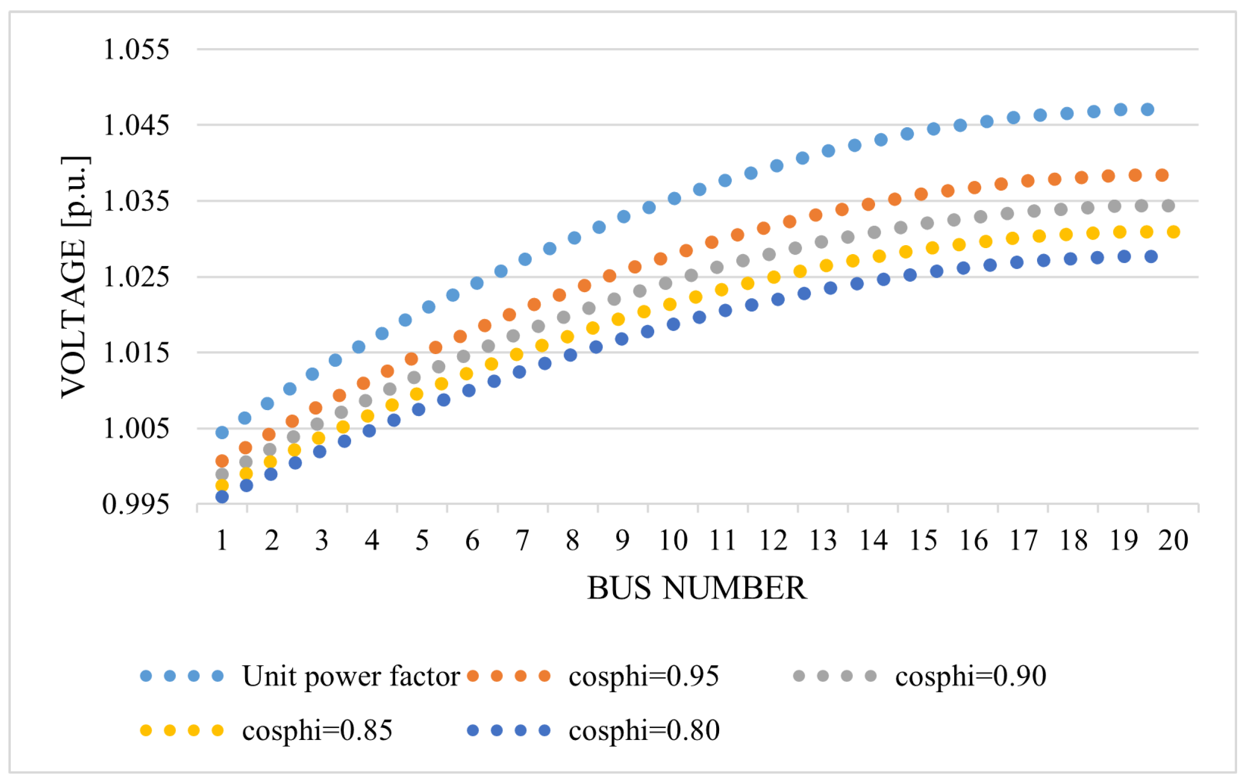
- the situation when PVs production is maximal and voltage rise along the feeder is present;
- the situation when PV inverters inject reactive power.
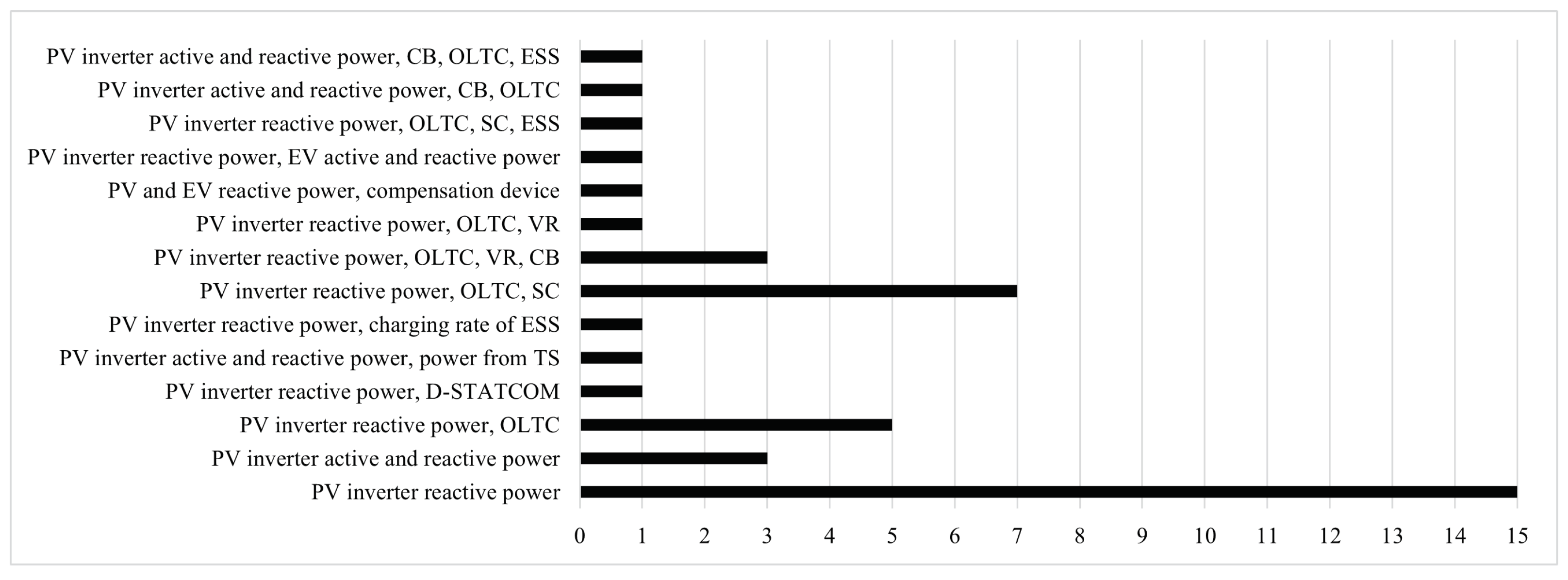
- Summary and classification of OPF objectives and variables in the case of voltage optimization in the DNs using PVs reactive power.
- Comparison of the used mathematical formulations of the OPFs and their connections to analytical or computational intelligence solution methods.
- Review of the different DN examples that are used for testing the developed optimization solutions.
2. PV Prosumers in Distribution Network
2.1. Prosumer Definition and Configuration
2.2. PV System Capabilities for Voltage Optimization
- fixed power factor mode;
- volt–VAR control;
- volt–watt control;
- mode for power rate limit;
- voltage balance mode.
2.3. PV Inverter Impact on Distribution Feeder Voltage Profile
3. Voltage Optimization in PV-Rich Distribution Networks—Objectives and Variables
3.1. General Formulation—Objectives and Variables
- control variables limit;
- limits for power generation (active and reactive power upper and lower limits);
- network operational limit determined in the network analysis (e.g., MVA limit).
- Voltage constraintwhere and are the lower and upper voltage limits.
- PV active and reactive power constraintwhere , , and are active, reactive, and apparent powers at bus i. is available active power at bus i.
- Line current (thermal) constraintwhere and are the lower and upper limits of the line current between buses i and k.
- OLTC tap position constraint (if it is included)where and are the lower and upper positions of OLTC tap at bus i.
- Capacitor constraint (if it is included)where and are the lower and upper limits of capacitor reactive power at bus i.
- Energy storage constraint (if it is included)where and are the lower and upper limits of the charge state of the storage system at time t.
3.2. Objectives and Variables—Discussion
4. Voltage Optimization in PV-Rich Distribution Networks—Formulation and Solution Methods
- nonlinear programming (NLP);
- linear programming (LP);
- quadratic programming (QP);
- mixed-integer linear programming (MILP);
- mixed-integer nonlinear programming (MINLP).
4.1. Analytical Methods
4.2. Computational Intelligence Methods
4.3. Formulation and Solution Methods—Discussion
4.4. Test Network Models
5. Conclusions
Author Contributions
Funding
Institutional Review Board Statement
Informed Consent Statement
Data Availability Statement
Acknowledgments
Conflicts of Interest
References
- Carvalho, P.M.S.; Correia, P.F.; Ferreira, L.A.F.M. Distributed reactive power generation control for voltage rise mitigation in distribution networks. IEEE Trans. Power Syst. 2008, 23, 766–772. [Google Scholar] [CrossRef]
- Kjaer, S.B.; Lazar, R.D.; Constantin, A.; Ballegaard, H.P.; Yang, G.; Østergaard, J.; Ipsen, H.H.; Frederiksen, K.H.B. Voltage control in low voltage networks by photovoltaic inverters—PVNET.DK. In Proceedings of the 28th European Photovoltaic Solar Energy Conference and Exhibition (28th EU PVSEC), Villepinte, France, 30 September–4 October 2013. [Google Scholar]
- Mokhtari, G.; Nourbakhsh, G.; Zare, F.; Ghosh, A. Overvoltage prevention in LV smart grid using customer resources coordination. Energy Build. 2013, 61, 387–395. [Google Scholar] [CrossRef]
- Xu, T.; Taylor, P.C. Voltage control techniques for electrical distribution networks including distributed generation. IFAC Proc. Vol. 2008, 41, 11967–11971. [Google Scholar] [CrossRef]
- Juamperez, M.; Yang, G.; Kjær, S.B. Voltage regulation in LV grids by coordinated volt-var control strategies. J. Mod. Power Syst. Clean Energy 2014, 2, 319–328. [Google Scholar] [CrossRef]
- Jamsek, S.; Tot, S.; Lasic, M.; Perisa, I.; Miklavcic, M. Regionaly important sincro.grid smart grid project. J. Energy Energ. 2018, 67, 86–93. [Google Scholar] [CrossRef]
- Turitsyn, K.; Šulc, P.; Backhaus, S.; Chertkov, M. Options for control of reactive power by distributed photovoltaic generators. Proc. IEEE 2011, 99, 1063–1073. [Google Scholar] [CrossRef]
- Takasawa, Y.; Akagi, S.; Yoshizawa, S.; Ishii, H.; Hayashi, Y. Effectiveness of updating the parameters of the Volt-VAR control depending on the PV penetration rate and weather conditions. In Proceedings of the 2017 IEEE Innovative Smart Grid Technologies–Asia (ISGT-Asia), Asia Smart Grid Smart Community, Auckland, New Zealand, 4–7 December 2017; pp. 1–5. [Google Scholar]
- Culjak, M.; Beus, M.; Pandzic, H. Development of a LabVIEW - Based Data Logging and Monitoring Application for a Photovoltaic Power Plant at FER. J. Energy Energ. 2022, 211, 14–18. [Google Scholar] [CrossRef]
- Petinrin, J.O.; Shaabanb, M. Impact of renewable generation on voltage control in distribution systems. Renew. Sustain. Energy Rev. 2016, 65, 770–783. [Google Scholar] [CrossRef]
- Karimi, M.; Mokhlis, H.; Naidu, K.; Uddin, S.; Bakar, A.H.A. Photovoltaic penetration issues and impacts in distribution network—A review. Renew. Sustain. Energy Rev. 2016, 53, 594–605. [Google Scholar] [CrossRef]
- Chaudhary, P.; Rizwan, M. Voltage regulation mitigation techniques in distribution system with high PV penetration: A review. Renew. Sustain. Energy Rev. 2018, 82, 3279–3287. [Google Scholar] [CrossRef]
- Nour, A.M.M.; Hatata, A.Y.; Helal, A.A.; El-Saadawi, M.M. Review on voltage-violation mitigation techniques of distribution networks with distributed rooftop PV systems. IET Gener. Transm. Distrib. 2020, 14, 349–361. [Google Scholar] [CrossRef]
- Antoniadou-Plytaria, K.E.A.; Kouveliotis-Lysikatos, I.N.; Georgilakis, P.S.; Hatziargyriou, N.D. Distributed and decentralized voltage control of smart distribution networks: Models, methods, and future research. IEEE Trans. Smart Grid 2017, 8, 2999–3008. [Google Scholar] [CrossRef]
- Ullah, Z.; Wang, S.; Wu, G.; Hasanien, H.M.; Jabbar, M.W.; Qazi, H.S.; Tostado-Véliz, M.; Turky, R.A.; Elkadeem, M.R. Advanced studies for probabilistic optimal power flow in active distribution networks: A scientometric review. IET Gener. Transm. Distrib. 2022, 16, 3579–3604. [Google Scholar] [CrossRef]
- Abdi, H.; Beigvand, S.D.; La Scala, M.N.D. A review of optimal power flow studies applied to smart grids and microgrids. Renew. Sustain. Energy Rev. 2017, 71, 742–766. [Google Scholar] [CrossRef]
- Toffler, A. The Third Wave: Learning for Tomorrow, the Futurists, the Schoolhouse and the City, 1st ed.; William Morrow and Company, Inc.: New York, NY, USA, 1980. [Google Scholar]
- Korotko, T.; Rosin, A.; Ahmadiahangar, R. Development of prosumer logical structure and object modeling. In Proceedings of the 2019 IEEE 13th International Conference on Compatibility, Power Electronics and Power Engineering (CPE-POWERENG), Sonderborg, Denmark, 23–25 April 2019. [Google Scholar]
- Cao, J.; Bu, Z.; Wang, Y.; Jiang, J.; Li, H.J. Detecting prosumer-community groups in smart grids from the multiagent perspective. IEEE Trans. Syst. Man. Cybern. Syst. 2019, 49, 1652–1664. [Google Scholar] [CrossRef]
- Rathnayaka, A.J.D.; Potdar, V.M.; Dillon, T.S.; Hussain, O.K.; Chang, E. A methodology to find influential prosumers in prosumer community groups. IEEE Trans. Ind. Inform. 2014, 10, 706–713. [Google Scholar] [CrossRef]
- Yang, H.; Xiong, T.; Qiu, J.; Qiu, D.; Dong, Z.Y. Optimal operation of DES/CCHP based regional multi-energy prosumer with demand response. Appl. Energy 2016, 167, 353–365. [Google Scholar] [CrossRef]
- Liu, N.; Cheng, M.; Yu, X.; Zhong, J.; Lei, J. Energy-sharing provider for PV prosumer clusters: A hybrid approach using stochastic programming and Stackelberg game. IEEE Trans. Ind. Electron. 2018, 65, 6740–6750. [Google Scholar] [CrossRef]
- Ghosh, A.; Aggarwal, V.; Wan, H. Exchange of renewable energy among prosumers using blockchain with dynamic pricing. arXiv 2018, arXiv:1804.08184v1. [Google Scholar]
- El Rahi, G.; Etesami, S.R.; Saad, W.; Mandayam, N.B.; Poor, H.V. Managing price uncertainty in prosumer-centric energy trading: A prospect-theoretic Stackelberg game approach. IEEE Trans. Smart Grid. 2019, 10, 702–713. [Google Scholar] [CrossRef]
- Garijalva, S.; Tariq, M.U. Prosumer-based smart grid architecture enables a flat, sustainable electricity industry. In Proceedings of the Innovative Smart Grid Technologies (ISGT), Sonderborg, Denmark, 23–25 April 2011. [Google Scholar]
- Lavrijssen, S.; Parra, A.C. Radical prosumer innovations in the electricity sector and the impact on prosumer regulation. Sustainability 2017, 9, 1207. [Google Scholar] [CrossRef]
- Merino, J.; Gómez, I.; Fraile-Ardanuy, J.; Santos, M.; Cortés, A.F.; Jimeno, B.J.; Madina, C. Chapter 6—Fostering DER integration in the electricity markets. In Distributed Energy Resources in Local Integrated Energy Systems; Graditi, G., Di Somma, M., Eds.; Elsevier: Amsterdam, The Netherlands, 2021. [Google Scholar]
- European Parliament DIRECTIVE (EU) 2019/944 of the European Parliament and of the Council on Common Rules for the Internal Market for Electricity and Amending Directive 2012/27/EU. Off. J. Eur. Union 2019, 125–199. Available online: https://eur-lex.europa.eu/legal-content/EN/TXT/?uri=celex%3A32019L0944 (accessed on 15 June 2022).
- Hrvatski Sabor Zakon o Tržištu Električne Energije. Narodne Novine 111/2021. 2021. Available online: https://narodne-novine.nn.hr/clanci/sluzbeni/2021_10_111_1940.html (accessed on 15 June 2022).
- Gebbran, D.; Mhanna, S.; Ma, Y.; Chapman, A.C.; Verbič, G. Fair coordination of distributed energy resources with Volt-Var control and PV curtailment. Appl. Energy 2021, 286, 116546. [Google Scholar] [CrossRef]
- Safayet, A.; Fajri, P.; Husain, I. Reactive power management for overvoltage prevention at high PV penetration in a low-voltage distribution system. IEEE Trans. Ind. Appl. 2017, 53, 5786–5794. [Google Scholar] [CrossRef]
- Yung, Y.; Han, C.; Lee, D.; Song, S.; Jang, G. Adaptive volt–var control in smart pv inverter for mitigating voltage unbalance at pcc using multiagent deep reinforcement learning. Appl. Sci. 2021, 11, 8979. [Google Scholar]
- Demirok, E.; Gonzalez, P.C.; Frederiksen, K.H.; Sera, D.; Rodriguez, P.; Teodorescu, R. Local reactive power control methods for overvoltage prevention of distributed solar inverters in low-voltage grids. IEEE J. Photovolt. 2011, 1, 174–182. [Google Scholar] [CrossRef]
- Dall’Anese, E.; Dhople, S.V.; Johnson, B.B.; Giannakis, G.B. Decentralized optimal dispatch of photovoltaic inverters in residential distribution systems. IEEE Trans. Energy Convers. 2014, 29, 957–967. [Google Scholar] [CrossRef]
- Jahangiri, P.; Aliprantis, D.C. Distributed Volt/VAr control by PV inverters. IEEE Trans. Power Syst. 2013, 28, 3429–3439. [Google Scholar] [CrossRef]
- Jabr, R.A. Robust volt/var control with photovoltaics. IEEE Trans. Power Syst. 2019, 34, 2401–2408. [Google Scholar] [CrossRef]
- Lee, H.; Kim, J.C.; Cho, S.M. Optimal volt-var curve setting of a smart inverter for improving its performance in a distribution system. IEEE Access 2020, 8, 157391–157945. [Google Scholar] [CrossRef]
- Su, X.; Masoum, M.A.S.; Wolfs, P.J. Optimal PV inverter reactive power control and real power curtailment to improve performance of unbalanced four-wire LV distribution networks. IEEE Trans. Sustain. Energy 2014, 5, 967–977. [Google Scholar] [CrossRef]
- Connell, A.O.; Keane, A. Volt-var curves for photovoltaic inverters in distribution systems. IET Gener. Transm. Distrib. 2017, 11, 730–739. [Google Scholar] [CrossRef]
- Fekete, K.; Klaic, Z.; Majdančić, L. Expansion of the residential photovoltaic systems and its harmonic impact on the distribution grid. Renew. Energy 2012, 43, 140–148. [Google Scholar] [CrossRef]
- DIgSILENT PowerFactory. Available online: https//www.digsilent.de/en/ (accessed on 4 June 2022).
- Growatt. Available online: https://www.ginverter.com/ (accessed on 10 June 2022).
- Carpentier, J. Contribuition to the economic dispatch problem. Bull. Soc. Fr. Des Electr. 1962, 8, 431–447. (In French) [Google Scholar]
- Dommel, H.W.; Tinney, W.F. Optimal power flow solutions. IEEE Trans. Power Appar. Syst. 1968, PAS-87, 1866–1876. [Google Scholar] [CrossRef]
- Momoh, J.A.; El-Hawary, M.E.; Adapa, R. A review of selected optimal power flow literature to 1993 part i: Nonlinear and quadratic programming approaches. IEEE Trans. Power Syst. 1999, 14, 96–103. [Google Scholar] [CrossRef]
- Momoh, J.A.; El-Hawary, M.E.; Adapa, R. A review of selected optimal power flow literature to 1993 part ii: Newton, linear programming and interior point method. IEEE Trans. Power Syst. 1999, 14, 96–104. [Google Scholar] [CrossRef]
- Huneault, M.; Galiana, F.D. A survey of the optimal power flow literature. IEEE Trans. Power Syst. 1991, 6, 762–770. [Google Scholar] [CrossRef]
- Momoh, J.A. Optimal Power Flow. In Electric Power System Applications of Optimization, 2nd ed.; CRC Press: Boca Raton, FL, USA, 2008; Chapter 12. [Google Scholar]
- Contaxis, G.C.; Delkis, C.; Korres, G. Decoupled optimal load flow using linear or quadratic programming. IEEE Power Eng. Rev. 1986, 1, 1–7. [Google Scholar]
- Biskas, P.N.; Bakirtzis, A.G. A decentralized solution to the Security Constrained DC-OPF problem of multi-area power systems. In Proceedings of the 2005 IEEE Russia Power Tech, St. Petersburg, Russia, 27–30 June 2005; Volume 18, pp. 1007–1013. [Google Scholar]
- Rau, N.S. Issues in the path toward an RTO and standard markets. IEEE Trans. Power Syst. 2003, 18, 435–443. [Google Scholar] [CrossRef]
- El-Hawary, M.E.; Bose, A.; de Barros, M.C.; El-Kieb, A.R.; Hammons, T.J.; Iwamoto, S.I. Power Engineering Letters. IEEE Power Eng. Rev. 2001, 21, 49–51. [Google Scholar] [CrossRef]
- Zhang, C.; Xu, Y.; Dong, Z.Y.; Zhang, R. Multi-objective adaptive robust voltage/VAR control for high-PV penetrated distribution networks. IEEE Trans. Smart Grid 2020, 11, 5288–5300. [Google Scholar] [CrossRef]
- Kundu, S.; Backhaus, S.; Hiskens, I.A. Distributed control of reactive power from photovoltaic inverters. In Proceedings of the 2013 IEEE International Symposium on Circuits and Systems (ISCAS), Beijing, China, 19–23 May 2013. [Google Scholar]
- Wu, R.; Liu, S. Deep learning based muti-objective reactive power optimization of distribution network with PV and EVs. Sensors 2022, 22, 4321. [Google Scholar] [CrossRef] [PubMed]
- Li, C.; Disfani, V.R.; Haghi, H.V.; Kleissl, J. Coordination of OLTC and smart inverters for optimal voltage regulation of unbalanced distribution networks. Electr. Power Syst. Res. 2020, 187, 106498. [Google Scholar] [CrossRef]
- Jafari, M.; Olowu, T.O.; Sarwat, A.I. Optimal smart inverters volt-VAR curve selection with a multi-objective volt-VAR optimization using evolutionary algorithm approach. In Proceedings of the 2018 North American Power Symposium (NAPS), Fargo, ND, USA, 9–11 September 2017. [Google Scholar]
- Ji, H.; Wang, C.; Li, P.; Zhao, J.; Song, G.; Ding, F.; Wu, J. A centralized-based method to determine the local voltage control strategies of distributed generator operation in active distribution networks. Appl. Energy 2018, 228, 2024–2036. [Google Scholar] [CrossRef]
- Carpinelli, G.; Mottola, F.; Proto, D.; Varilone, P. Minimizing unbalances in low-voltage microgrids: Optimal scheduling of distributed resources. Appl. Energy 2017, 191, 170–182. [Google Scholar] [CrossRef]
- Frank, S.; Steponavice, I.; Rebennack, S. Optimal power flow: A bibliographic survey I: Formulations and deterministic methods. Energy Syst. 2012, 3, 221–258. [Google Scholar] [CrossRef]
- Bacher, R. Netzleittechnik und Optimierung Elektrischer Netze; ETH Zürich: Zürich, Switzerland, 2000. [Google Scholar]
- Olowu, T.O.; Jafari, M.; Sarwat, A.I. A multi-objective optimization technique for volt-Var control with high PV penetration using genetic algorithm. In Proceedings of the 2018 North American Power Symposium (NAPS), Fargo, ND, USA, 9–11 September 2018. [Google Scholar]
- Lu, W.; Liu, M.; Liu, Q. Increment-exchange-based decentralized multiobjective optimal power flow for active distribution grids. IEEE Syst. J. 2020, 14, 3695–3704. [Google Scholar] [CrossRef]
- Shailendra, S.; Pamshetti, V.B.; Thakur, A.K.; Singh, S.P. Multistage multiobjective Volt/VAR control for smart grid-enabled CVR with solar PV penetration. IEEE Syst. J. 2020, 15, 2767–2778. [Google Scholar]
- Zhong, C.; Sakis Meliopoulos, A.P.; Xie, B.; Xie, J.; Liu, K. Multi-stage quadratic flexible optimal power flow with a rolling horizon. IEEE Trans. Smart Grid 2021, 12, 3128–3137. [Google Scholar] [CrossRef]
- Ramadan, A.; Ebeed, M.; Kamel, S. Performance assessment of a realistic Egyptian distribution network including PV penetration with DSTATCOM. In Proceedings of the 2019 International Conference on Innovative Trends in Computer Engineering (ITCE), Aswan, Egypt, 2–4 February 2019. [Google Scholar]
- Xu, R.; Zhang, C.; Xu, Y.; Dong, Z.; Zhang, R. Multi-objective hierarchically-coordinated volt/var control for active distribution networks with droop-controlled PV inverters. IEEE Trans. Smart Grid 2022, 13, 998–1011. [Google Scholar] [CrossRef]
- Yang, H.T.; Liao, J.T. MF-APSO-based multiobjective optimization for PV system reactive power regulation. IEEE Trans. Sustain. Energy 2015, 6, 1346–1355. [Google Scholar] [CrossRef]
- Jabr, R.A. Linear decision rules for control of reactive power by distributed photovoltaic generators. IEEE Trans. Power Syst. 2018, 33, 2165–2174. [Google Scholar] [CrossRef]
- Zhang, Q.; Dehghanpour, K.; Wang, Z. Distributed CVR in unbalanced distribution systems With PV penetration. IEEE Trans. Smart Grid 2018, 10, 5308–5319. [Google Scholar] [CrossRef]
- Al-Ja’Afreh, M.A.A.; Mokryani, G. Voltage unbalance mitigation in low voltage distribution networks using time series three-phase optimal power flow. In Proceedings of the 2021 56th International Universities Power Engineering Conference (UPEC), Middlesbrough, UK, 7–10 September 2020. [Google Scholar]
- Robbins, B.A.; Domínguez-García, A.D. Optimal reactive power dispatch for voltage regulation in unbalanced distribution systems. IEEE Trans. Power Syst. 2016, 31, 2903–2913. [Google Scholar] [CrossRef]
- Guggilam, S.S.; Dall’Anese, E.; Chen, Y.C.; Dhople, S.V.; Giannakis, G.B. Scalable optimization methods for distribution networks with high PV integration. IEEE Trans. Smart Grid 2016, 7, 2061–2070. [Google Scholar] [CrossRef]
- Der Lee, Y.; Lin, W.C.; Jiang, J.L.; Cai, J.H.; Huang, W.T.; Yao, K.C. Optimal individual phase voltage regulation strategies in active distribution networks with high PV penetration using the sparrow search algorithm. Energies 2021, 14, 2061. [Google Scholar]
- Su, X.; Liu, Y.; Tian, S.; Ling, P.; Fu, Y.; Wei, S.; SiMa, C. A multi-stage coordinated volt-Var optimization for integrated and unbalanced radial distribution networks. Energies 2020, 13, 4877. [Google Scholar] [CrossRef]
- Il Go, S.; Yun, S.Y.; Ahn, S.J.; Choi, J.H. Voltage and reactive power optimization using a simplified linear equations at distribution networks with DG. Energies 2020, 13, 3334. [Google Scholar]
- Jin, D.; Chiang, H.D.; Li, P. Two-timescale multi-objective coordinated volt/var optimization for active distribution networks. IEEE Trans. Power Syst. 2019, 34, 4418–4428. [Google Scholar] [CrossRef]
- Ammar, M.; Sharaf, A.M. Optimized Use of PV distributed generation in voltage regulation: A probabilistic formulation. IEEE Trans. Ind. Inform. 2019, 15, 247–256. [Google Scholar] [CrossRef]
- Chen, Y.; Luckey, B.; Wigmore, J.; Davidson, M.; Benigni, A. Real-time volt/var optimization for distribution systems with photovoltaic integration. In Proceedings of the IECON 2017-43rd Annual Conference of the IEEE Industrial Electronics Society, Beijing, China, 29 October–1 November 2017. [Google Scholar]
- Chen, Y.; Strothers, M.; Benigni, A. Day-ahead optimal scheduling of PV inverters and OLTC in distribution feeders. In Proceedings of the 2016 IEEE Power and Energy Society General Meeting (PESGM), Boston, MA, USA, 17–21 July 2016. [Google Scholar]
- Ceylan, O.; Liu, G.; Tomasovic, K. Coordinated distribution network control of tap changer transformers, capacitors and PV inverters. Electr. Eng. 2018, 100, 1133–1146. [Google Scholar] [CrossRef]
- Li, C.; Disfani, V.R.; Haghi, H.V.; Kleissl, J. Coordinated voltage control for active distribution network considering the impact of energy storage. Energy Procedia 2019, 158, 1122–1127. [Google Scholar]
- Xu, J.; Wang, J.; Liao, S.; Sun, Y.; Ke, D.; Li, X.; Liu, J.; Jiang, Y.; Wei, C.; Tang, B. Stochastic multi-objective optimization of photovoltaics integrated three-phase distribution network based on dynamic scenarios. Appl. Energy 2018, 231, 985–996. [Google Scholar] [CrossRef]
- Ding, F.; Zhang, Y.; Simpson, J.; Bernstein, A.; Vadari, S. Optimal energy dispatch of distributed PVS for the next generation of distribution management systems. IEEE Open Access J. Power Energy 2020, 7, 287–295. [Google Scholar] [CrossRef]
- Sidea, D.O.; Picioroaga, I.I.; Tudose, A.M.; Bulac, C.; Tristiu, I. Multi-objective particle swarm optimization applied on the optimal reactive power dispatch in electrical distribution systems. In Proceedings of the 2020 International Conference and Exposition on Electrical and Power Engineering (EPE), Iasi, Romania, 22–23 October 2020. [Google Scholar]
- Zhao, J.; Liu, X.; Lin, C.; Wei, W. Three-phase unbalanced voltage/VAR optimization for active distribution networks. In Proceedings of the 2016 IEEE Power and Energy Society General Meeting (PESGM), Boston, MA, USA, 17–21 July 2016. [Google Scholar]
- Zhu, H.; Liu, H.J. Fast local voltage control under limited reactive power: Optimality and stability analysis. IEEE Trans. Power Syst. 2015, 31, 3794–3803. [Google Scholar] [CrossRef]
- Jin, D.; Chiang, H.D. Multi-objective look-ahead reactive power control for active distribution networks with composite loads. In Proceedings of the 2018 IEEE Power & Energy Society General Meeting (PESGM), Portland, OR, USA, 5–10 August 2018. [Google Scholar]
- Ma, W.; Wang, W.Z.; Chen, Z.; Hu, R. A centralized voltage regulation method for distribution networks containing high penetrations of photovoltaic power. Int. J. Electr. Power Energy Syst. 2021, 129, 106852. [Google Scholar] [CrossRef]
- Pamshetti, V.B.; Singh, S.P. Optimal coordination of PV smart inverter and traditional volt-VAR control devices for energy cost savings and voltage regulation. Int. Trans. Electr. Energy Syst. 2019, 29, 1–24. [Google Scholar] [CrossRef]
- Lee, H.J.; Yoon, K.H.; Shin, J.W.; Kim, J.C.; Cho, S.M. Optimal parameters of volt-var function in smart inverters for improving system performance. Energies 2020, 13, 2294. [Google Scholar] [CrossRef]
- Frank, S.; Steponavice, I.; Rebennack, S. Optimal power flow: A bibliographic survey II: Non-deterministic and hybrid methods. Energy Syst. 2012, 3, 259–289. [Google Scholar] [CrossRef]
- Stott, B.; Alsac, O.; Monticelli, A.J. Security Analysis and Optimization. Proc. IEEE 1987, 75, 1623–1644. [Google Scholar] [CrossRef]
- Alsac, B.; Bright, O.J.; Praise, M.; Stott, B. Further developments in LP-based optimal power flow. IEEE Trans. Power Syst. 2003, 5, 435–443. [Google Scholar] [CrossRef]
- Unum, M.R.; Box, P. Network constrained security control using an interior point algorithm. IEEE Trans. Power Syst. 1993, 8, 1068–1076. [Google Scholar]
- Tinney, W.F.; Ashley, B.; Brewer, B.; Hughes, A. Optimal power flow by Newton approach. IEEE Power Eng. Rev. 1984, PER-4, 2864–2880. [Google Scholar]
- Alsac, O.; Stott, B. Optimal load flow with steady-state security. IEEE Trans. Power Appar. Syst. 1974, PAS-93, 745–751. [Google Scholar] [CrossRef]
- Burchett, R.C.; Happ, H.H.; Vierath, D.R.; Wirgau, K.A. Developments in optimal power flow. IEEE Trans. Power Appar. Syst. 1982, PAS-101, 406–414. [Google Scholar] [CrossRef]
- Peschon, J.; Bree, D.W.; Hajdu, L.P. Optimal power-flow solutions for power system planning. Proc. IEEE 1972, 6, 64–70. [Google Scholar] [CrossRef]
- Torres, G.L.; Quintana, V.H. On a nonlinear multiple-centrality-corrections interior-point method for optimal power flow. IEEE Trans. Power Syst. 2001, 16, 222–228. [Google Scholar] [CrossRef]
- Chang, S.-K.; Albuyeh, F.; Gilles, M.L.; Marks, G.E.; Kato, K. Optimal real-time voltage control. IEEE Trans. Power Syst. 1990, 5, 750–758. [Google Scholar] [CrossRef]
- AlRashidi, M.R.; El-Hawary, M.E. Applications of computational intelligence techniques for solving the revived optimal power flow problem. Electr. Power Syst. Res. 2009, 79, 694–702. [Google Scholar] [CrossRef]
- Hartati, R.S.; El-Hawary, M.E. Optimal active power flow solutions using a modified Hopfield neural network. In Proceedings of the Canadian Conference on Electrical and Computer Engineering 2001, Toronto, ON, Canada, 13–16 May 2001. [Google Scholar]
- Bakirtzis, A.G.; Biskas, P.N.; Zoumas, C.E.; Petridis, V. Optimal power flow by enhanced genetic algorithm. IEEE Trans. Power Syst. 2002, 17, 229–236. [Google Scholar] [CrossRef]
- Gaing, Z.L. Constrained optimal power flow by mixed-integer particle swarm optimization. In Proceedings of the IEEE Power Engineering Society General Meeting, San Francisco, CA, USA, 16 June 2005. [Google Scholar]
- Swarup, K.S. Swarm intelligence approach to the solution of optimal power flow. J. Indian Inst. Sci. 2006, 86, 439–455. [Google Scholar]
- Teng, J.; Liu, Y. A novel ACS-based optimum switch relocation method. IEEE Trans. Power Syst. 2003, 18, 113–120. [Google Scholar] [CrossRef]
- Vlachogiannis, J.G.; Hatziargyriou, N.D.; Lee, K.Y. Ant colony system-based algorithm for constrained load flow problem. IEEE Trans. Power Syst. 2005, 20, 1241–1249. [Google Scholar] [CrossRef]
- Mishra, S. Bacteria foraging based solution to optimize both real power loss and voltage stability limit. In Proceedings of the 2007 IEEE Power Engineering Society General Meeting, Tampa, FL, USA, 24–28 June 2007. [Google Scholar]
- Roa-Sepulveda, C.A.; Pavez-Lazo, B.J. A solution to the optimal power flow using simulated annealing. In Proceedings of the 2001 IEEE Porto Power Tech Proceedings, Porto, Portugal, 10–13 September 2001. [Google Scholar]
- Abido, M.A. Optimal power flow using tabu search algorithm. Electr. Power Compon. Syst. 2002, 30, 469–483. [Google Scholar] [CrossRef]
- Venkatesh, B.; Sadasivam, G.; Khan, M. Optimal reactive power planning against voltage collapse using the successive multiobjective fuzzy LP technique. IEEE Proc. Gener. Transm. Distrib. 1999, 146, 343–348. [Google Scholar] [CrossRef]
- Li, C.; Chen, Y.-A.; Jin, C.; Sharma, R.; Kleissl, J. Online PV smart inverter coordination using deep deterministic policy gradient. Electr. Power Syst. Res. 2021, 209, 107988. [Google Scholar] [CrossRef]
- Utama, C.; Meske, C.; Schneider, J.; Ulbrich, C. Reactive power control in photovoltaic systems through (explainable) artificial intelligence. Appl. Energy 2021, 328, 120004. [Google Scholar] [CrossRef]
- OpenDSS. Available online: https://www.epri.com/pages/sa/opendss (accessed on 8 September 2022).
- Rossoni, P.; Belati, E.A.; da S. Benedito, R. A hybrid approach for optimization of electric power distributed networks with photovoltaic sources. Electr. Power Syst. Res. 2022, 211, 108183. [Google Scholar] [CrossRef]


| Review Paper | Year | Focused Topics | Prosumer | Notes |
|---|---|---|---|---|
| [10] | 2016 | Impact of distributed generation (DG) on voltage control on DNs | Yes | Reviewed voltage control with DG with a focus on smart network technologies—demand side management (DSM) and energy storage systems (ESS) |
| [11] | 2016 | PV impact on DNs including voltage regulation issues, harmonic, and islanding operation | Yes | Reviewed issues caused by PV penetration in DN insight voltage regulation, harmonic, and islanding operation, and proposed technical solution |
| [14] | 2017 | Distributed and decentralized voltage control in smart DNs | Yes | Reviewed smart DNs according to communication systems, control models, and methods |
| [16] | 2017 | Application of OPF in smart DNs and microgrids | Yes | Reviewed OPF according to objectives, constraints, methods, and challenges |
| [12] | 2018 | Mitigation methods for voltage regulation in DNs with PV | Yes | Discussed ESS strategies, active power curtailment-based strategies, and reactive power control strategies |
| [13] | 2020 | Mitigation methods for voltage violation in DNs with PV systems | Yes | Presented different mitigation methods for voltage regulation in DNs and their merits and shortcomings |
| [15] | 2022 | Probabilistic OPF in active DNs | Yes | Scientometric review of OPF in active DNs—characteristics and challenges |
| Objective | Formulation | Explanation |
|---|---|---|
| Power loss minimization [53,54,55] | , —voltage magnitude at ith and kth buses —phase angle ith and kth elements of conductance and —square value of current and resistance of branch line from bus i to bus k | |
| OLTC tap operation minimization [56] | M—number of discrete devices —status of discrete device m at time t | |
| APC minimization [58] | —curtailed active power of PV at time t | |
| PV inverter loss minimization [38] | p—phases —set of buses with PVs —apparent power , , —coefficients of each inverter’s efficiency data | |
| Reactive power inj./abs. minimization [57] | and —injected/absorbed reactive power | |
| Cost of energy minimization [59] | —price of energy at tth time —active power imported from the external network at time t —duration of time intervals | |
| Security margin maximization [59] | —line current in lth line at time t —ampacity of line current in lth line |
| Reference | Single/ Multi-Objective | Objectives | Variables |
|---|---|---|---|
| [62] | multi-objective | min VD from 0.95 pu threshold, min losses, min reactive power from capacitors | PV inverter reactive power, OLTC, SC, and |
| [63] | multi-objective | min losses, min VD—DN, min active power curtailed from available power—prosumer | PV active and reactive power |
| [64] | multi-objective | min VD from expected CVR voltage, min losses | PV inverter reactive power, OLTC/AVR, and CBs |
| [65] | single-objective | min VD | PV inverter reactive power, OLTC |
| [38] | multi-objective | min losses, min VD, min VUF, min PV generation cost, min PV APC cost | PV inverter reactive power |
| [66] | multi-objective | min losses, min VD, improvement VSI | PV inverter reactive power and static compensator |
| [53,54,67,68,69] | multi-objective | min losses, min VD | PV inverter reactive power |
| [70] | multi-objective | min VD, min losses | PV inverter reactive power, CBs, and OLTC |
| [71] | single-objective | min VUF | PV inverter active and reactive power, power injected by TS |
| [72] | single-objective | min VD | PV inverter reactive power |
| [73] | multi-objective | min losses, min cost of APC and generated/consumed reactive power, min VD | PV inverter reactive power |
| [74] | multi-objective | min VD, min voltage unbalance | PV inverter reactive power, OLTC, VR, and CB |
| [75] | multi-objective | min losses, min VD, min VUF | PV inverter reactive power |
| [32] | single-objective | min VUF | PV inverter reactive power |
| [76] | single-objective | min VD | PV inverter reactive power, OLTC |
| [77] | multi-objective | min losses, min VD, min control action of OLTC and SC | PV inverter reactive power, OLTC, SC |
| [78] | single-objective | min VD | PV inverter reactive power, OLTC |
| [79] | multi-objective | min VD, min losses | PV inverter reactive power, OLTC, and SC |
| [57] | multi-objective | min VD, min losses, min reactive power injection, and absorption | PV inverter reactive power |
| [80] | multi-objective | min VD, min losses | PV inverter reactive power, OLTC |
| [81] | single-objective | min VD | PV inverter reactive power, OLTC, and VR |
| [58] | multi-objective | min VD, min losses, min APC | PV inverter reactive power, OLTC and CB |
| [55] | multi-objective | min VD, min losses | PV and EV inverter reactive power, the compensation device |
| [56] | multi-objective | min VD, min OLTC tap operation | PV inverter reactive power, OLTC |
| [82] | single-objective | min VD | PV inverter reactive power, charge/discharge rate of ESS |
| [83] | multi-objective | min losses, min VUF | PV inverter reactive power |
| [34] | multi-objective | min cost, min losses, min cost associated with active power setpoints, min VD | PV inverter active and reactive power |
| [84] | multi-objective | min active and reactive power output, min VD | PV inverter active and reactive power |
| [37] | multi-objective | min VD, min losses, min peak of reactive power | PV inverter reactive power |
| [85] | multi-objective | min VD, min losses | PV inverter reactive power, OLTC, CB |
| [59] | multi-objective | min VUF, min cost of purchased energy, min peak shaving, min losses, min SMI, min VD | PV inverter reactive power, EV active and reactive power, bus voltages at all time intervals of the day |
| [86] | multi-objective | min VUF, min losses | PV inverter reactive power, OLTC, CB |
| [87] | single-objective | min VD | PV inverter reactive power |
| [88] | multi-objective | min VD, min losses | PV inverter reactive power, SC, OLTC, ESS |
| [89] | multi-objective | min VD, min losses, min number of switching operations of OLTC and CB, min APC | PV inverter active and reactive power, CB, OLTC |
| [90] | multi-objective | min VD, min operational cost | PV inverter active and reactive power, CB, OLTC, ESS |
| [91] | multi-objective | min VD, min losses, min peak of reactive power | PV reactive power |
| [39] | single-objective | min VD | PV inverter reactive power |
| Formulation | Analytical Methods | Reference |
|---|---|---|
| NLP | ADMM-based method IPM SQP | [69] [36] [54] |
| LP | SLP | [63] |
| QP | QP Gradient projection methods ADMM-based method | [52,53,74] [59,82] [70,71] |
| MILP | MILP | [58] |
| MINLP | QP IPM | [74] [76] |
| Formulation | Computational Intelligence Methods | Reference |
|---|---|---|
| NLP | GA | [37,57] |
| MINLP | GA | [62] |
| NLP | NDSGA II | [83] |
| NLP | PSO | [68,82] |
| MINLP | PSO | [64,85,88,114] |
| NLP | SCA | [66] |
| MINLP | C&CG algorithm | [53] |
| NLP | SSA | [74] |
| MINLP | GWO | [81] |
| MINLP | Modified PSO, DLF algorithm | [75] |
| MINLP | MOPSO, IPM | [77] |
| MINLP | GA, PSA | [79] |
| NLP | PREA, SPEA2, NSGA-II, NSGA-III, ToP, DDNN | [55] |
| MINLP | FP | [67] |
| MINLP | PSA | [80] |
| MINLP | NSGA-III | [89] |
| MINLP | -constrained method and FL | [90] |
| MINLP | DDPG | [113] |
| MINLP | ANN | [114] |
| Advantages | Shortcomings | |
|---|---|---|
| Analytical methods (simplex method, SLP, SQP, ADMM, gradient projection method, IPM) |
|
|
| Computational intelligence methods (evolutionary and biologically inspired methods, artificial intelligence methods, FL) |
|
|
| Reference | Test Network Model | Voltage Level | Balanced/Unbalanced |
|---|---|---|---|
| [32,79,80] | IEEE–34 bus | MV–24.9 kV and 4.16 kV | Balanced |
| [70] | IEEE–34 bus modified according to balance | MV–24.9 kV and 4.16 kV | Unbalanced |
| [55,63,67,81,82,85,89,90] | IEEE–33 bus | MV–12.66 kV | Balanced |
| [63] | Real–266 bus, Shenzen, China | MV–20 kV | Balanced |
| [53,64,83,88,113] | IEEE-123 bus | MV–4.16 kV | Unbalanced |
| [70,72] | IEEE–123 bus modified according to balance | MV–4.16 kV | Balanced |
| [65] | Real distribution feeder–187 bus | MV–12.47 kV and LV–120/240 V | Balanced |
| [38,75] | Perth Solar City–101 bus | LV–415/240 V | Unbalanced |
| [66] | Tala City, Egypt–37 bus | MV–11 kV | Balanced |
| [67,76,78,81] | IEEE–69 bus | MV–12.66 kV | Balanced |
| [32,57] | IEEE–13 bus | MV–4.16 kV | Balanced |
| [70] | IEEE–13 bus | MV–4.16 kV | Unbalanced |
| [71] | Real UK l | LV–0.4 kV | Unbalanced |
| [72] | IEEE–15 bus | MV–11 kV | Unbalanced |
| [74] | IEEE–8500 bus | MV and LV | Both |
| [75] | Real Australian–565 bus | MV–22 kV and LV–415 V | Both |
| [68] | 22 bus | MV–11.4 kV | Balanced |
| [78] | 17 bus | MV–25 kV | Balanced |
| [56,113] | IEEE–37 bus | MV–4.16 kV | Unbalanced |
| [56] | Real Californian utility feeder–2884 bus | N/A | Unbalanced |
| [34] | Illustrative model | LV | N/A |
| [84] | K1 feeder–1747 bus in the southeastern US | MV and LV | N/A |
| [69,116] | 33 bus | MV–12.66 kV | N/A |
| [69] | 830 bus | N/A | N/A |
| [37,91] | Real South Korean–20 bus | MV–22.9 kV | Balanced |
| [59] | Real South Italian–16 bus | LV | Unbalanced |
| [39] | Real Irish suburban–85 bus | LV | N/A |
| [58] | Modified PG&E–69 bus | MV | Balanced |
| [114] | CIGRE–12 bus | MV | N/A |
| [116] | 118 bus | MV | N/A |
Publisher’s Note: MDPI stays neutral with regard to jurisdictional claims in published maps and institutional affiliations. |
© 2022 by the authors. Licensee MDPI, Basel, Switzerland. This article is an open access article distributed under the terms and conditions of the Creative Commons Attribution (CC BY) license (https://creativecommons.org/licenses/by/4.0/).
Share and Cite
Dubravac, M.; Fekete, K.; Topić, D.; Barukčić, M. Voltage Optimization in PV-Rich Distribution Networks—A Review. Appl. Sci. 2022, 12, 12426. https://doi.org/10.3390/app122312426
Dubravac M, Fekete K, Topić D, Barukčić M. Voltage Optimization in PV-Rich Distribution Networks—A Review. Applied Sciences. 2022; 12(23):12426. https://doi.org/10.3390/app122312426
Chicago/Turabian StyleDubravac, Marina, Krešimir Fekete, Danijel Topić, and Marinko Barukčić. 2022. "Voltage Optimization in PV-Rich Distribution Networks—A Review" Applied Sciences 12, no. 23: 12426. https://doi.org/10.3390/app122312426
APA StyleDubravac, M., Fekete, K., Topić, D., & Barukčić, M. (2022). Voltage Optimization in PV-Rich Distribution Networks—A Review. Applied Sciences, 12(23), 12426. https://doi.org/10.3390/app122312426