Article

Effect of Robot Motion Accuracy on Surface Form during Computer-Controlled Optical Surfacing Process

1
Department of Information Management, School of Government, Beijing Normal University, Beijing 100089, China
2
Manufacturing Metrology Team, Faculty of Engineering, University of Nottingham, Nottingham NG8 1BB, UK
3
School of Mechanical Engineering, Tianjin University, Tianjin 300350, China
*
Author to whom correspondence should be addressed.
Appl. Sci. 2022, 12(23), 12301; https://doi.org/10.3390/app122312301
Submission received: 27 October 2022 / Revised: 19 November 2022 / Accepted: 29 November 2022 / Published: 1 December 2022
(This article belongs to the Special Issue Advances in Intelligent Robots and Precision Machining)

Abstract

:
Nowadays, large-aperture optical components are increasingly used in high-power laser systems, remote-sensing satellites, and space-based astronomical telescopes. Fabricating these surfaces with submicron-scale shape accuracy and a nanoscale surface finish has been a great challenge for the optical industry, especially for hard and difficult-to-machine materials. Thus, to achieve the high-efficiency and high-precision polishing of large-aperture aspherical optical parts, this study combined robotic machining technology with computer-controlled optical surfacing (CCOS) technology and investigated the effect of robot motion accuracy on the surface topography of workpieces during polishing. First, a material removal model considering the normal error of the polishing tool was developed based on contact mechanics, kinematic theory, and the abrasion mechanism. Next, in combination with the polishing trajectory, the surface morphology and form accuracy after polishing were predicted under different normal-error conditions. Then, preliminary experiments were conducted to verify the model. The experimental data agreed with the simulation results, showing that as the normal error increased from 0° to 0.5° and 1°, the peak-to-valley (PV) values of the surface profile of the optical element decreased from 5.42, 5.28, and 4.68 μm to 3.97, 4.09, and 4.43 μm, respectively. The corresponding convergence rates were 26.8%, 22.5%, and 5.3%. The root mean square (RMS) values decreased from 0.754, 0.895, and 0.678 μm to 0.593, 0.620, and 0.583 μm, with corresponding convergence rates of 21.4%, 30.7% and 14.0%, respectively. Moreover, a higher motion accuracy enabled the polishing robot to reduce the mid- and high-frequency errors of the optical element.

1. Introduction

The applications of aspheric surfaces in optical systems not only improve performance but also significantly reduce the number of optical components, therefore reducing the manufacturing cost of optical systems [1]. These advantages mean that large-aperture aspherical surfaces are widely used in high-power laser systems, remote-sensing satellites, and space-based astronomical telescopes [2]. However, increasing the size and accuracy requirements of aspheric optical components often increases the processing difficulty. Taking the Hubble Space Telescope as an example, the main lens with a diameter of 2.4 m had a surface form error of 2 μm, which shortened the observation distance from the expected value of 14 billion light years to 4 billion light years [3]. The James Webb Space Telescope, originally scheduled to launch in 2018, was also delayed because of the demanding design and manufacturing requirements for the optical components. Therefore, the fabrication of large-aperture aspherical surfaces with high efficiency and accuracy is an important issue in the optical manufacturing industry.
Various ultra-precision polishing processes are available for polishing aspheric surfaces and off-axis segments, including computer-controlled optical surfacing (CCOS) [4], bonnet polishing [5], magnetorheological finishing [6], stress lap polishing [7], and ion figuring [8]. Because each polishing process has its own merits and limitations, the most suitable method for a specific function must be selected in the process chain. For example, Beaucamp et al. [9] performed the super-smooth finishing of diamond-turned hard X-ray molding dies by combined fluid jet polishing and bonnet polishing. Kim et al. [10] used a combined polishing technique, including stress lap polishing and rigid conformal polishing, to achieve the ultra-precision machining of large-aperture off-axis mirrors. By choosing reasonable polishing parameters, the proposed polishing method could improve the surface roughness RMS value of the polished surface to below 1 nm [11].
The computer-controlled optical surfacing (CCOS) technique is an enabling technology that actively controls the position, orientation, and dwell time of a small rotating tool as it sweeps through the polished surface to construct the desired optical contour in an iterative process [12]. CCOS can provide a solution for the low-cost mass production of large-aperture optical surfaces because of its advantages of high polishing efficiency and shape accuracy [13]. Jones and Plante [6] reported that the form error of the large optic (up to four meters in size) was reduced from 24 μm to 1.9 μm, and a surface texture with a 1.6 nm RMS value could be achieved for a 1 m diameter optic [14]. In the polishing process, the convergence accuracy and efficiency of the surface form achieved by CCOS mainly depend on the influence function, the dwell time algorithm, and the tool path planning. Hence, much research has been conducted on improving the polishing process [15], edge control [16], dwell time calculation [17], and polishing path generation [18]. During the polishing process of aspherical surfaces, the normal error of the polishing tool relative to the workpiece affects the pressure and velocity distribution in the contact area, resulting in the distortion of the removal function and the deterioration of the polishing efficiency and accuracy. However, research on the theoretical modeling and influence mechanism of the motion accuracy of polishing equipment on surface topography during the polishing process is still limited.
Given these considerations, a novel material removal model considering the normal error of the polishing tool was developed based on contact mechanics, kinematic theory, and the abrasion mechanism. In combination with the polishing trajectory, the surface morphology and form accuracy after polishing were predicted under different normal-error conditions. A series of experiments was conducted to verify the model and clarify the influence mechanism of the normal error on the surface topography in CCOS. The established model provides a solid theoretical basis for the optimization of robot motion control strategies.

2. Model Development

Figure 1 shows a flowchart of the theoretical modeling process for CCOS. Firstly, the surface topography of the polishing pad was simulated by a mathematical statistics method to determine the porous distribution characteristics of the polishing pad. Secondly, the microscopic deformation characteristics of the polishing pad under a given tool load were calculated using the data of the pad surface topography, and the contact pressure at each particle during polishing was calculated based on contact mechanics, so as to determine the embedded depth and material removal of each particle. Then, considering the planetary-motion characteristics and the normal error of the polishing tool, the material removal amount of all effective abrasive particles on the entire polishing pad was calculated; subsequently, the material removal characteristics of the planetary-motion polishing were determined. Finally, the polishing trajectory and the initial surface topography were combined to predict the surface topography and form accuracy after polishing.

2.1. Modeling of Pad Surface Topography

The polishing tool used in this paper was a porous polyurethane polishing pad. The pad surface was distributed with circular micropores and 2 mm × 1.5 mm diversion grooves. During the polishing process, the surface topography of the pad has a very important influence on the removal mechanism of the polishing material. Therefore, in order to better understand the material removal process, it is necessary to study the surface topography characteristics of polishing pads. In this research, a KEYENCE VH7000 digital microscope was used to observe the surface morphology of the polishing pad, and the image recognition method was used to analyze and measure the distribution of the porous features on the pad surface. Figure 2a shows the measurement results of the surface morphology of the polyurethane polishing pad. We observed randomly distributed pores of different sizes on the pad surface. Figure 2b shows the pore distribution on the pad surface treated by the image recognition method. After the statistical analysis of the size of the pore area, we concluded that the pore area on the pad surface in the observation area accounted for 35% of the total observation area. In addition, the pore size on the pad surface was statistically analyzed, demonstrating that the average pore size was 85 μm, and the fitted distribution curve showed an exponential distribution. After the hypothesis test, we found that the distribution of the micropore diameter D h on the pad surface was exponential, with a mean value of 85 μm, that is, D h ~ ε ( 0.085   mm ) . In this study, Matlab software was used to simulate the surface topography characteristics of the polishing pad. The simulation steps were as follows:
i.
We estimated the average spacing Δ h between the micropores on the pad surface by observing the total number of micropores on the pad surface N h and the total surface area of the polishing pad S p , as shown in Equation (1).
Δ h S p / N h
The d g value was taken as the average spacing of uniformly distributed micropores, and the position of the center point of the micropores was expressed as G x y z . Since the distribution of micropores mostly presented a disordered random position distribution, the position of the center point of the micropores was randomly shifted in the x , y , and z directions of the spatial coordinates, as follows:
G x y z = G i , j , k x G i , j , k y G i , j , k z = G 0 , 0 , 0 x + i d g + R x G 0 , 0 , 0 y + j d g + R y G 0 , 0 , 0 z + k d g + R z
where R x , R y , and R z represent the random offset of the initial center point position of the micropore in the three directions of x , y , and z , respectively.
ii.
After the random displacement of the center position of the micropore was determined, the hemispherical “micropore” was simulated at the new position, with the diameter of the micropore obeying an exponential distribution with an average value of 85 μm, so as to simulate the pore distribution characteristics of the pad surface.
iii.
The statistical analysis of the distribution characteristics of the micropore diameter on the pad surface and the porosity of the pad surface was conducted. Compared with the measured data, if the error of the simulation result was less than 5%, the simulation met the requirements. Otherwise, we re-sampled and simulated the position of the central hole of the micropore until the micropore distribution characteristics met the requirements.
iv.
According to the distribution characteristics of the diversion grooves and the central hole on the pad surface, the height of the slurry supply hole and the position of the groove in the theoretical model was set to −1.5 mm; then, the theoretical simulation morphology of the polishing pad surface was generated.

2.2. Removal Mechanism for Single Particle

In the present study, the abrasive particles were assumed to be evenly distributed between the polishing pad and the polishing surface, with some of the abrasive particles embedding into the polishing surface under the action of the tool load. Combined with the rotation of the polishing tool, the target surface is scratched by the abrasive particles to achieve the removal of the material. To simplify the modeling process, the influence of the polishing liquid film was ignored in this study, and the contact between the abrasive particles and the workpiece surface was assumed to be elastomer–solid contact. Assuming that the load applied to the polishing tool was borne by the abrasive particles, the applied load could be expressed as:
F l o a d = H w π D p m = 1 N w d m z ,
where H w is the hardness of the polished workpiece, and d m z is the embedded depth of the mth abrasive particle. The indentation of micron-sized abrasive particles can cause the microscopic plastic deformation of the target surface. According to the wear and fracture mechanism of hard and brittle materials, submicron-scale plastic deformation causes the phase transformation of the material itself on the microscopic level without generating dislocations, subsurface defects, or microcracks. The material removal model established in this section was also based on the assumption of microscopic plastic deformation. The macroscopic material removal characteristics of the workpiece surface were determined by the microscopic material removal caused by the plastic deformation of a single abrasive particle. The material removal caused by the single particle Δ M R V m could be described as [19]:
Δ M R V m = 2 π n r D p 1 / 2 d m 3 / 2 r m Δ t ,
where n r is the rotation speed of the polishing tool, D p is the diameter of the abrasive particle, and d m is the embedded depth of the m th abrasive particle. The embedded depth of the abrasive particles is related to the load applied to the polishing tool and the material properties of the polishing surface.

2.3. Material Removal Model under Planetary Motion

The material removal of the sample surface is caused by the scratching action of the effective abrasive particles as the polishing tool rotates [2]. Therefore, the material removal under planetary motion could be determined by the cumulative superposition of the material removal of individual abrasive particles under the planetary motion trajectory. In the planetary-motion polishing process, the material removal rate at any point in the polishing area can be expressed as the cumulative superposition of the material removal rate of a single particle in one motion cycle at any time. Therefore, the material removal rate M M R n at the n th point in the polishing area under planetary motion could be expressed as:
M M R n = φ n e 60 m = 1 M Δ M R V m A m Δ t ( m = 1 , 2 , 3 , , M ) ,
where n e is the revolution speed of the polishing tool; M is the number of abrasive particles that can remove the surface material in the polishing area effectively; φ is the overlapping influence coefficient; and A m is the microscopic contact area of the m th particle across the surface, which can be represented as A m = 2 π r m d r m . The amount of material removed is not only related to the load applied to the tool, the rotation/revolution speed of the polishing tool, and the eccentricity of the revolution, but also to the surface topography characteristics of the polishing pad and the characteristics of the abrasive particles.

2.4. Material Removal Considering the Normal Error of the Polishing Tool

In practical polishing processes, many factors, such as the polishing pad wear, the concentration change of the polishing slurry, and the motion error of the polishing equipment, affect material removal [15]. The normal error of the polishing tool, that is, the deviation between the rotation axis of the polishing tool and the normal direction of the polishing surface, is an important factor that affects the material removal characteristics. However, the mechanism of its influence on the profile accuracy of the polished surface has rarely been reported. The normal error of the polishing tool directly alters the material removal distribution in the processing area, which in turn affects the surface shape accuracy of the polished surface. The theoretical derivation of material removal presented in this section considered the effect of the normal error of the polishing tool on the material removal characteristics of the polished surface under planetary motion. The formulation of Equation (4) was based on the assumption that the loads applied to the polishing tool are normal to the polished surface. When the polishing axis produces a certain inclination angle with the normal direction of the workpiece surface along any direction, the material removal caused by a single abrasive particle at this time can be expressed as:
Δ M R V m = 2 π n r D p 1 / 2 d m θ 3 / 2 r m Δ t cos θ ,
where d m θ is the embedded depth of the m th abrasive particle when the normal error of polishing tool is θ .

2.5. Surface Generation Considering Normal Error of Polishing Tool

When the polishing tool with planetary motion sweeps the entire workpiece surface according to a certain polishing path, the material removal amount at any position x , y on the workpiece surface can be determined by the superposition of the material removal amount at this position when the polishing tool sweeps all trajectory points. Therefore, the material removal amount H x , y at any point on the polished surface could be expressed as:
H x , y = i = 1 N x j = 1 N y P ( i , j ) x , y M M R ( i , j ) x , y * R x , y θ , t ,
where M M R ( i , j ) x , y is the material removal amount at position x , y when the polishing tool moves to the trajectory point i , j ; P ( i , j ) x , y is the discrete trajectory of the adopted polish path; R x , y θ , t is the normal error of the polishing tool at any time, which can be generated by the random number function in the simulation processing program; and N x and N y represent the number of the discrete points in the X and Y directions on the polished surface, respectively. The initial surface profile before polishing is H i n i t i a l x , y , and the surface profile after polishing H z x , y is expressed as:
H z x , y = H i n i t i a l x , y H x , y .

3. Experimental Design

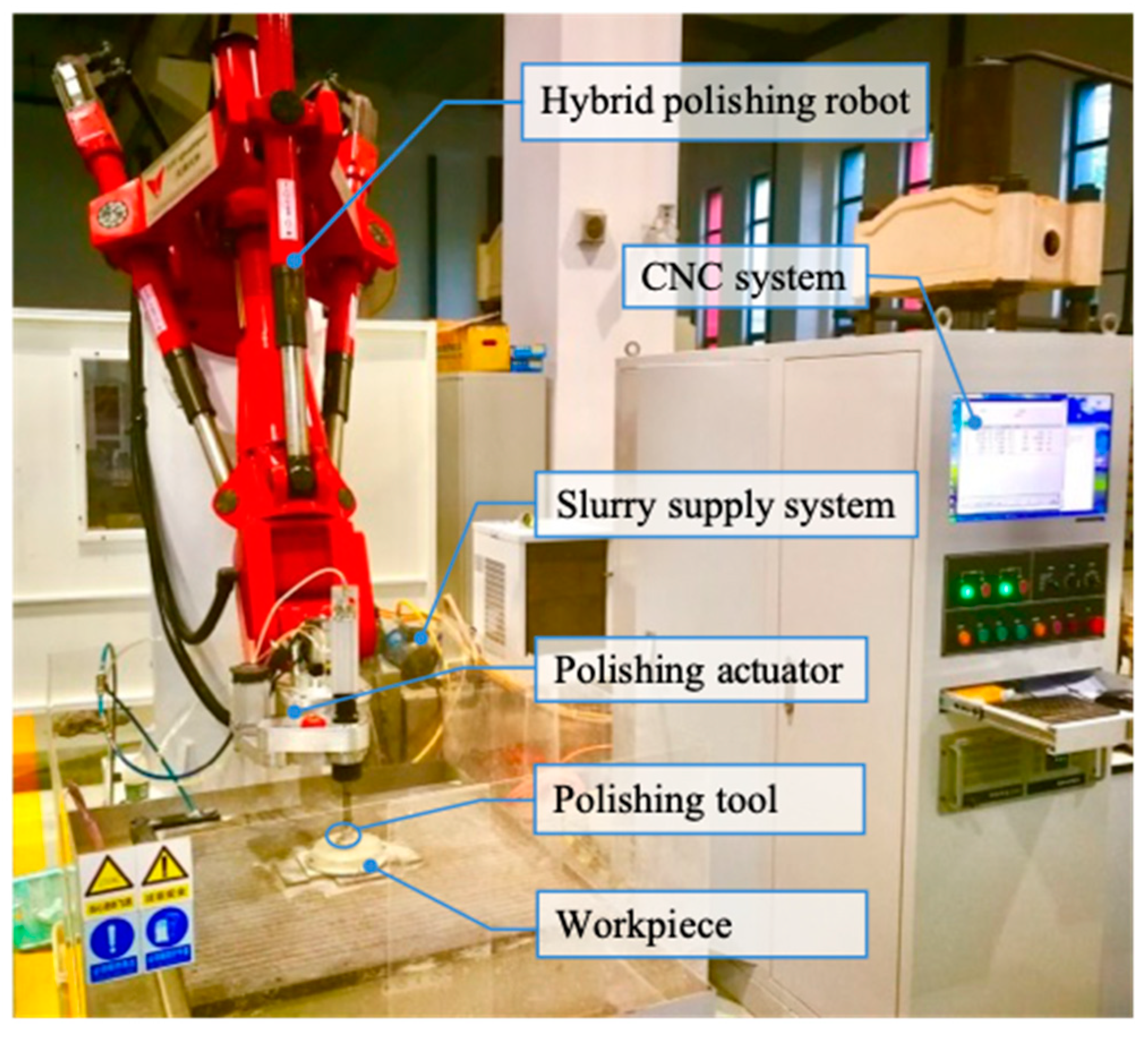
The experimental research presented in this section combined robotic machining technology with the CCOS process to achieve the high-efficiency and high-precision polishing of large-diameter aspheric optical parts. Figure 3 shows the experimental robotic polishing device for the CCOS process, which consisted of a six-degrees-of-freedom hybrid robot system, a polishing slurry supply and circulation system, a polishing head, and a computer numerical control (CNC) system. During the experiment, the polishing slurry was pressurized by the slurry supply pump and then injected into the center hole of the polishing tool, and the rotational speed, pressure, and motion trajectory of the polishing tool were controlled by the robot numerical control system. The K9 optical glass sample with a diameter of 120 mm and a curvature of 0.01198 was polished by cerium oxide polishing slurry with a concentration of 15% and a particle size of 1 μm. A polyurethane polishing tool with a radius of 10 mm was used in the experiment, which had a revolution speed of 60 rpm, a rotation speed of 600 rpm, a load of 0.15 Mpa, and an eccentricity of 4 mm. The polished samples were measured with a Nanovea white-light interferometer with a sampling spacing of 20 μm.
To study the influence of the robot motion accuracy on the machining accuracy of the optical components, we carried out processing experiments using polishing tools with different normal errors for experimental groups A, B, and C. As shown in Figure 4, the polishing paths of the three groups of experiments were discretized into 11 × 11 machining traces. The position and normal vector of each processing track point could be calculated according to the geometric features of the optical element to determine the polishing position and attitude control when the polishing robot scanned each track point. In the group A polishing experiment, the normal error of the polishing tool when the polishing robot scanned each track point was 0. In the group B polishing experiment, the normal error of the polishing tool at different track points was randomly assigned values between −0.5° and 0.5°. In the group C polishing experiment, the normal error of the polishing tool at different track points was also randomly generated, but its value was kept between −1° and 1°. Figure 5a,b present the random normal-error distributions generated for the group B and C polishing experiments, respectively.

4. Results and Discussion

Figure 6a shows the theoretically calculated surface topography of a 40 × 40 mm polishing pad. Figure 6b presents a partial schematic diagram of the distribution of micropores on the pad surface (5 mm × 5 mm), with micropores of different sizes being evenly distributed on the pad surface. The surface porosity of the polishing pad obtained by simulation was 35.8%, and the error between the simulated distribution and the measurement results was within the allowable range. The surface of the actual polishing pad had a 2 × 1.5 mm diversion groove and a slurry supply hole with a diameter of 4 mm in the center, so the simulated pad surface morphology is shown in Figure 6c. Figure 6d presents a photograph of a 40 mm diameter porous polyurethane polishing pad, showing that the pore distribution characteristics of the simulated surface were basically consistent with the real structure.
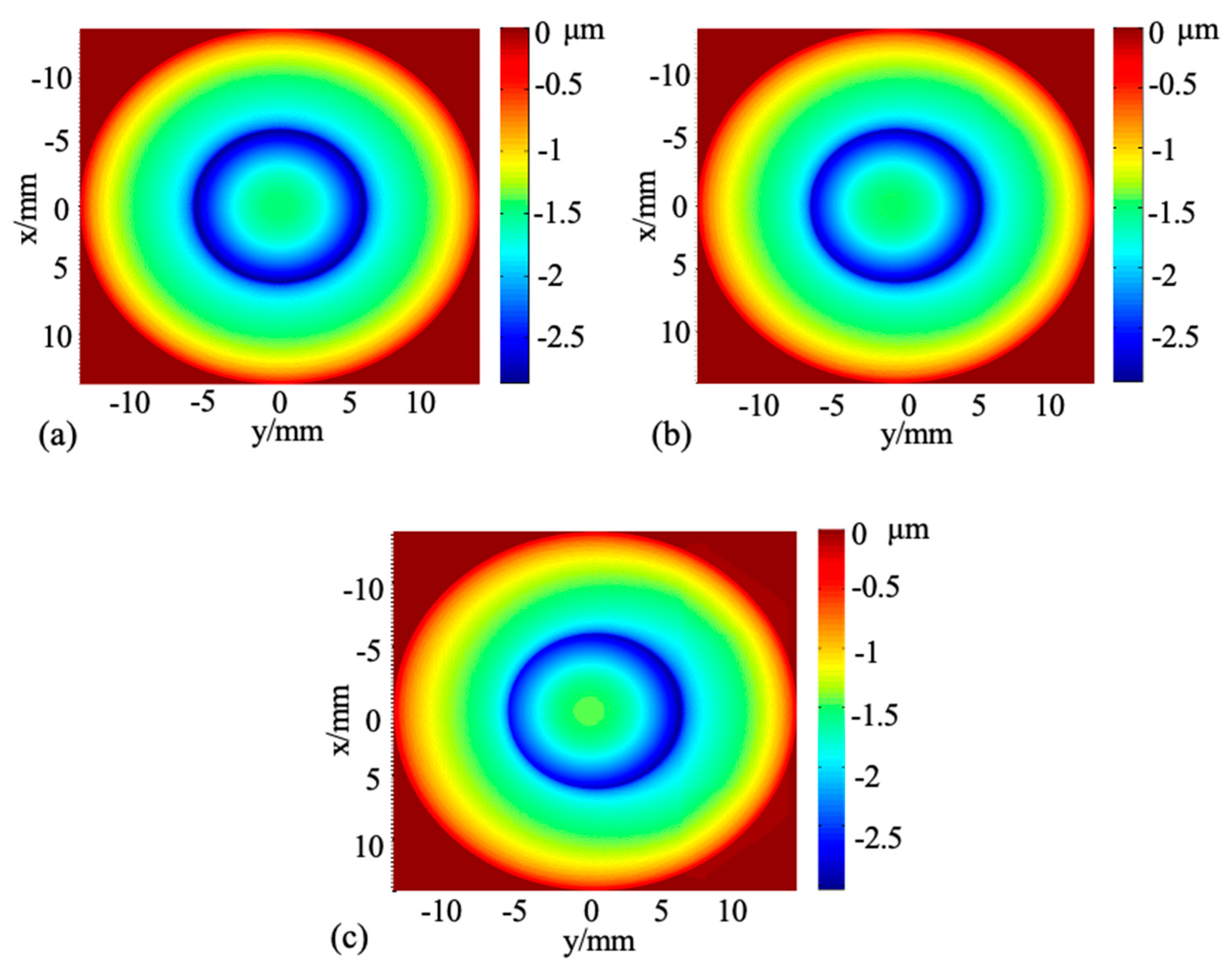
Figure 7 shows the three-dimensional material removal characteristics of planetary-motion polishing with different normal errors. The simulation results showed that when the normal error was 0, the removal topography of the material presented a perfect axisymmetric distribution. However, when the normal error increased to 0.5°, the material removal topography was skewed, and the maximum removal depth increased. When the normal phase error continued to increase to 1°, the material removal profile exhibited a severe unilateral collapse, and the material removal along the inclined side increased significantly. The reason for this was that the force on the material surface in the single-spot removal was uneven due to the error of the normal accuracy, resulting in the uneven removal of the material, which eventually increased the error of the actual machined surface relative to the ideal surface.
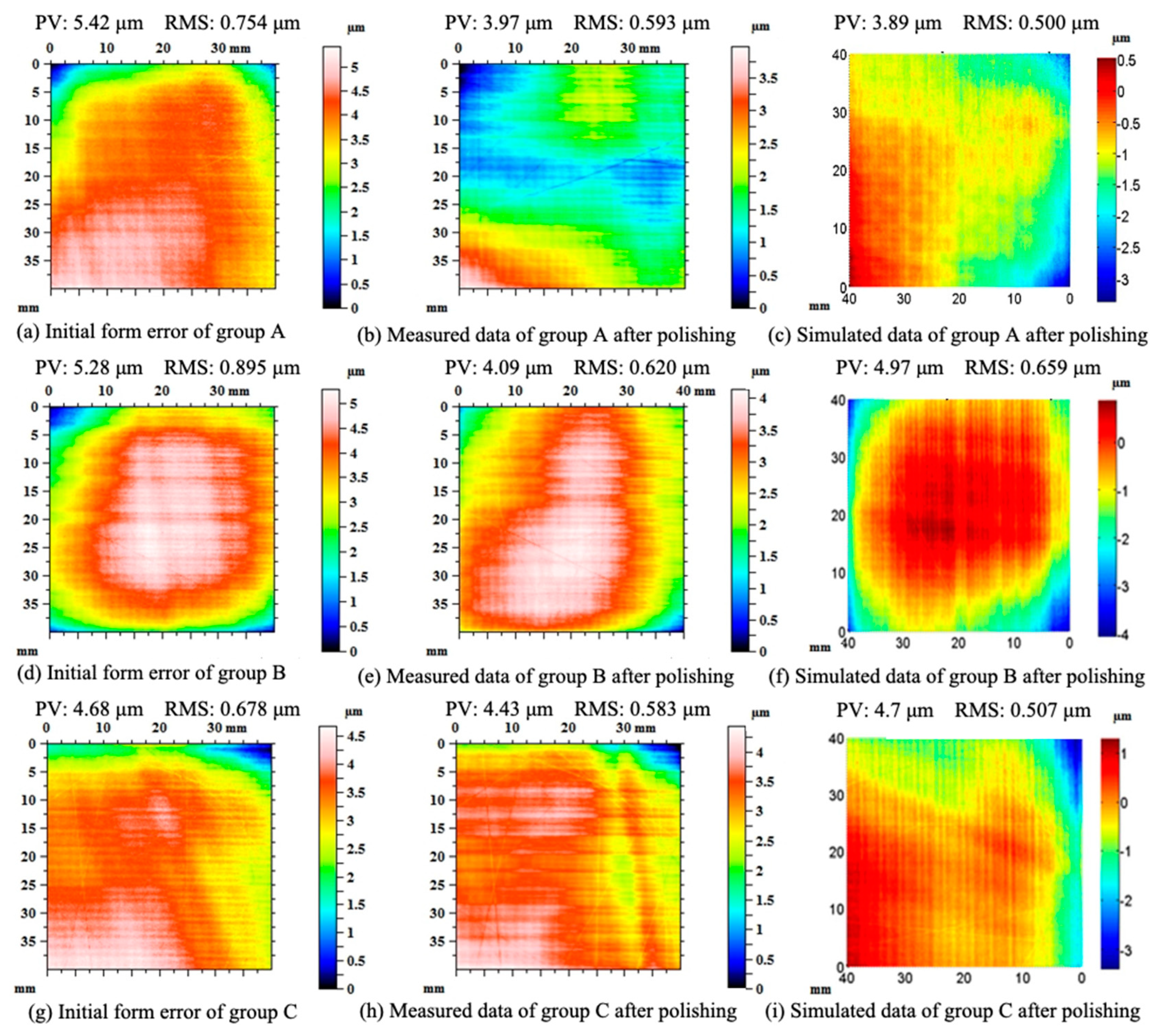
Figure 8 shows the experimental and simulated surface profiles for different polishing-tool normal errors. When the normal error of the polishing tool was 0°, 0.5°, and 1°, the PV values of the simulated surfaces were 3.89, 4.97, and 4.7 μm, which showed good agreement with the experimentally measured PV values of 3.97, 4.09, and 4.43 μm, respectively. At the same time, the RMS values of the simulated surfaces were 0.500, 0.659, and 0.507 μm, which were also very consistent with the RMS values of the experimentally measured surfaces of 0.593, 0.620, and 0.583 μm, respectively. The experimental results showed that as the normal error increased from 0° to 0.5° and 1°, the PV values of the surface profile of the optical element decreased from 5.42, 5.28, and 4.68 μm to 3.97, 4.09, and 4.43 μm, respectively. The corresponding convergence rates were 26.8%, 22.5%, and 5.3%. The RMS values decreased from 0.754, 0.895, and 0.678 μm to 0.593, 0.620, and 0.583 μm, with corresponding convergence rates of 21.4%, 30.7%, and 14.0%, respectively. According to the comparative analysis of the PV and RMS numerical convergence rates of the three sets of polishing experiments, as the normal error of the polishing tool gradually increased, the overall convergence rate of the PV and RMS values of the optical element after polishing decreased. The convergence rate of the RMS value was relatively high under the normal error of 0.5°, which may have been caused by the surface error distribution of convex and concave in the group B optical elements. The established theoretical model successfully predicted the influence of the normal error on the form accuracy. According to the analysis of the surface error of the experimental and simulated polishing surface, the higher the normal error of the polishing robot, the greater the reduction in the contour accuracy of the surface after polishing and the larger the decrease in the surface convergence efficiency in the practical polishing process.
Figure 9 shows the PSD distribution of the polished surface for three different polishing-tool normal errors. The results showed that the motion accuracy of the polishing robot had a substantial influence on the medium- and high-frequency errors after polishing. As the normal error of the polishing robot gradually increased, the relative changes in the medium- and high-frequency errors before and after polishing gradually decreased, because the random change in the normal error of the polishing robot caused an uneven force to be exerted on each point of the polishing pad as the polishing process progressed, resulting in an uneven material removal rate and the suppression of medium- and high-frequency errors. Therefore, the higher the motion accuracy of the polishing robot, the higher the convergence efficiency of the optical element surface. Additionally, the mid- and high-frequency errors of the optical element could be reduced to a certain extent.

5. Conclusions

This paper presented a study involving the modeling, simulation, and testing of surface generation considering the motion accuracy of the polishing device. A theoretical model was developed to predict and simulate the effect of different normal errors on surface generation. The simulation results showed that when the normal error increased from 0° to 1°, the removal topography of the material changed from perfect axisymmetric distribution to severe unilateral collapse, and the material removal along the inclined side increased significantly.
A series of surface polishing tests was conducted by combining robotic machining technology with CCOS technology to verify the theoretical model under different normal-error conditions. The experimental data reasonably agreed with the simulation results. The results also indicated that as the normal error increased from 0° to 0.5° and 1°, the peak-to-valley (PV) values of the surface profile of the optical element decreased from 5.42, 5.28, and 4.68 μm to 3.97, 4.09, and 4.43 μm, respectively. The corresponding convergence rates were 26.8%, 22.5%, and 5.3%. The root mean square (RMS) values decreased from 0.754, 0.895, and 0.678 μm to 0.593, 0.620, and 0.583 μm, with corresponding convergence rates of 21.4%, 30.7%, and 14.0%, respectively. Furthermore, the improvement of the mid- and high-frequency errors was significantly weakened. Therefore, the influence of the robot motion accuracy on the surface integrity of the polished workpiece needs to be further examined in future research, and it is necessary to study robot motion control strategies to improve the surface convergence efficiency.

Author Contributions

Conceptualization, Y.-T.C. and Z.-C.C.; methodology, M.L. and Z.-C.C.; software, Y.-T.C.; validation, Y.-T.C. and Z.-C.C.; formal analysis, Y.-T.C. and M.L.; investigation, Y.-T.C. and M.L.; resources, Z.-C.C.; data curation, Y.-T.C.; writing—original draft preparation, Y.-T.C.; writing—review and editing, M.L. and Z.-C.C.; visualization, Y.-T.C. and M.L.; supervision, Z.-C.C.; project administration, Z.-C.C.; funding acquisition, Z.-C.C. All authors have read and agreed to the published version of the manuscript.

Funding

This research was funded by the Key Projects of Tianjin Science and Technology Support Program, grant number 18JCZDJC38900.

Conflicts of Interest

The authors declare no conflict of interest.

References

  1. Kumar, S.; Tong, Z.; Jiang, X. Advances in the design and manufacturing of novel freeform optics. Int. J. Extrem. Manuf. 2022, 4, 032004. [Google Scholar] [CrossRef]
  2. Lin, B.; Li, K.L.; Cao, Z.-C.; Huang, T. Modeling of pad surface topography and material removal characteristics for computer-controlled optical surfacing process. J. Mater. Process. Technol. 2019, 265, 210–218. [Google Scholar] [CrossRef]
  3. Li, S.; Dai, Y. CCOS Technology Based on Small Polishing Pad; John Wiley & Sons, Ltd.: Hoboken, NJ, USA, 2017. [Google Scholar]
  4. Ke, X.L.; Wang, T.Y.; Zhang, Z.L.; Huang, L.; Wang, C.J.; Negi, V.S.; Pullen, W.C.; Choi, H.; Kim, D.; Idir, M. Multi-tool optimization for computer controlled optical surfacing. Opt. Express 2022, 30, 16957–16972. [Google Scholar] [CrossRef]
  5. Cao, Z.-C.; Cheung, C.F.; Ho, L.T.; Liu, M.Y. Theoretical and experimental investigation of surface generation in swing precess bonnet polishing of complex three-dimensional structured surfaces. Precis. Eng. 2017, 50, 361–371. [Google Scholar] [CrossRef]
  6. Wan, S.; Wei, C.; Hu, C.; Situ, G.; Shao, Y.; Shao, J. Novel magic angle-step state and mechanism for restraining the path ripple of magnetorheological finishing. Int. J. Mach. Tools Manuf. 2021, 161, 103673. [Google Scholar] [CrossRef]
  7. West, S. Development and Results for Stressed-lap Polishing of Large Telescope Mirrors. In Optical Fabrication and Testing; Optica Publishing Group: Washington, DC, USA, 2014; p. OTh2B-4. [Google Scholar]
  8. Wang, Y.B.; Dai, Y.F.; Hu, H.; Du, C.Y.; Bao, J.H. Study on rapid convergence strategy of nano-precision optical surface by ion beam figuring. Opt. Commun. 2022, 507, 127614. [Google Scholar] [CrossRef]
  9. Beaucamp, A.; Namba, Y. Super-smooth finishing of diamond turned hard X-ray molding dies by combined fluid jet and bonnet polishing. CIRP Ann.—Manuf. Technol. 2013, 62, 315–318. [Google Scholar] [CrossRef]
  10. Kim, D.W.; Burge, J.H.; Davis, J.M.; Martin, H.M.; Tuell, M.T.; Graves, L.R.; West, S.C. New and Improved Technology for Manufacture of GMT Primary Mirror Segments. In Advances in Optical and Mechanical Technologies for Telescopes and Instrumentation II; Navarro, R., Burge, J.H., Eds.; Proceedings of SPIE; SPIE: Bellingham, WA, USA, 2016; Volume 9912. [Google Scholar]
  11. Kim, D.W.; Burge, J.H. Rigid conformal polishing tool using non-linear visco-elastic effect. Opt. Express 2010, 18, 2242–2257. [Google Scholar] [CrossRef] [PubMed] [Green Version]
  12. Zhang, J.; Wang, H. Generic model of time-variant tool influence function and dwell-time algorithm for deterministic polishing. Int. J. Mech. Sci. 2021, 211, 106795. [Google Scholar] [CrossRef]
  13. Liao, D.; Yuan, Z.; Tang, C.; Xie, R.; Chen, X. Mid-Spatial Frequency Error (PSD-2) of optics induced during CCOS and full-aperture polishing. J. Eur. Opt. Soc.-Rapid 2013, 8, Artn 13031. [Google Scholar] [CrossRef]
  14. Jones, R.A.; Plante, R.L. Rapid fabrication of large aspheric optics. Precis. Eng. 1987, 9, 65–70. [Google Scholar] [CrossRef]
  15. Lin, B.; Jiang, X.-M.; Cao, Z.-C.; Huang, T. Development and theoretical analysis of novel center-inlet computer-controlled polishing process for high-efficiency polishing of optical surfaces. Robot. Comput.-Integr. Manuf. 2019, 59, 1–12. [Google Scholar] [CrossRef]
  16. Wan, S.; Zhang, X.; Wang, W.; Xu, M.; Jiang, X. Edge control in precision robotic polishing based on space-variant deconvolution. Precis. Eng. 2019, 55, 110–118. [Google Scholar] [CrossRef]
  17. Kang, H.; Wang, T.Y.; Choi, H.; Kim, D. Genetic algorithm-powered non-sequential dwell time optimization for large optics fabrication. Opt. Express 2022, 30, 16442–16458. [Google Scholar] [CrossRef] [PubMed]
  18. Xie, Y.H.; Yang, J.X.; Huang, W.L.; Li, J. A tool-path planning method used in computer controlled optical surfacing based on improved prim algorithm. Int. J. Adv. Manuf. Technol. 2022, 119, 5917–5927. [Google Scholar] [CrossRef]
  19. Lin, B.; Jiang, X.M.; Cao, Z.C.; Huang, T.; Li, K.L. Theoretical and experimental analysis of material removal and surface generation in novel fixed abrasive lapping of optical surface. J. Mater. Process. Technol. 2019, 279, 116570. [Google Scholar] [CrossRef]
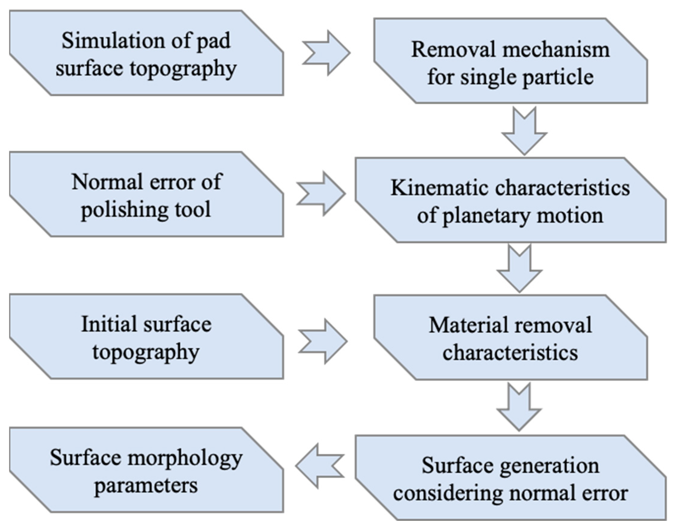
Figure 1. Flowchart of the theoretical modeling process for CCOS.
Applsci 12 12301 g001
Figure 2. Surface morphology of polishing pad: (a) 3D morphology, (b) pore distribution.
Applsci 12 12301 g002
Figure 3. Experimental robotic polishing device for the CCOS process.
Applsci 12 12301 g003
Figure 4. Discretization of polishing path and illustration of tool normal error for corresponding machining tracks.
Applsci 12 12301 g004
Figure 5. Normal-error distribution of polishing tools used in group (a) B and (b) C polishing experiments.
Applsci 12 12301 g005
Figure 6. Simulation of surface morphology of polishing pad: (a) surface pore distribution, (b) micropore characteristics, (c) surface morphology of polishing pad with diameter of 40 mm, (d) actual photo of polishing pad.
Applsci 12 12301 g006
Figure 7. 3D material removal characteristics when normal errors of polishing tool were (a) 0°, (b) 0.5°, and (c) 1°.
Applsci 12 12301 g007
Figure 8. Experimental and simulated form error distribution for different motion accuracies.
Applsci 12 12301 g008
Figure 9. PSD curves for the normal errors of (a) 0°, (b) 0.5°, and (c) 1°.
Applsci 12 12301 g009
Publisher’s Note: MDPI stays neutral with regard to jurisdictional claims in published maps and institutional affiliations.