Abstract
Existing studies on the dynamic characteristics of planetary gearboxes are generally based on traditional modeling methods. The models were idealized because of various uncertain factors that affect the dynamic characteristics of the planetary gearbox. The influence of non-mechanical components, such as driving motors, on dynamic analysis, is often ignored. Digital twin technology can not only simulate the data characteristics of physical entities to realize the real-time state evaluation and fault diagnosis of complex equipment but also reflect the entity characteristics of the modeled object completely. Therefore, a digital twin multi-body dynamic model of a planetary gearbox is established for detecting the combined fault of the sun gear missing teeth and the planetary gear missing teeth or pitting under different working conditions. The dynamic characteristics of a planetary gearbox subjected to electromechanical coupling were studied. The sun gear fault frequency, planetary gear fault frequency, and both related modulation frequencies appear in the experiment, and the corresponding fault characteristic frequencies also appear in the digital twin simulation. The validity of the proposed model was experimentally verified. Finally, the root-mean-square index was used to analyze the fault sensitivity of the traditional and digital twin models. The results show that the fault diagnosis effect of the digital twin model has a significant advantage, thus verifying the necessity of considering the effect of electromechanical coupling on the dynamic characteristics of the planetary gearbox.
1. Introduction
Owing to the compact structure and high-power transmission efficiency of the transmission mechanism of the planetary gearbox, the planetary gearbox transmission mechanism has been widely used in wind turbines, automobiles, ships, aerospace, and other machinery. In terms of the planetary gear train design, the literature [1,2] proposes a new method for planetary gear train (PGT) analysis, which simplifies the design process of the planetary gear and provides guidance for practical applications. The literature [3,4] evaluated the effect of the vibration activity of gearbox housings made of composite materials and showed that housings made of composite materials have comparable or lower vibration levels at higher gear speeds and that composite gearbox housings can be a good alternative to steel solutions. The literature [5] discusses the results of a study of the original system condition monitoring of a three-stage transmission, the main objective of which was to establish the frequency characteristics of the gearing, to determine whether it is possible to perform a vibroacoustic diagnosis of the same transmission under conditions of considerable influence and to analyze the influence of the sensor mounting point on the effectiveness of the signal diagnosis. In the context of rigid body entanglement, the literature [6,7] studied the rotational motion of a body fixed at a point, with the former representing this graphically, showing the variation of the parameters of the body during the motion, and the latter using the Krylov–Bogoliubov–Mitropolski (KBM) method to obtain an approximate solution for the kinematic system, a work that is used in physics, engineering, and the aeronautical industry. With regard to the geometric model of planetary gear teeth, due to the more difficult manufacturing of the convex–concave gear profile in comparison to the involute one, an application example was defined that suppressed this disadvantage [8]. An improved algorithm for herringbone gear tooth topology modification based on the overlap rate is proposed in the literature [9], and the superiority of the improved topology-modified gear pair is verified in terms of both statics and dynamics.
Planetary gearboxes are prone to failures during long-term operation, and if these failures are not detected and eliminated in time, they will cause uneven forces on the gear mesh, accelerate the wear of the gear teeth, and lead to the failure of other gears meshed with them, i.e., combined failures. Therefore, it is very necessary to establish a planetary gearbox dynamics model to study the effects of different levels of combined failures on the dynamic characteristics of planetary gear systems and to provide the necessary information for fault diagnosis and reliability studies on the planetary gearbox. In the literature [10,11,12,13], gear dynamic models containing different faults were established and the mechanisms of the different faults were analyzed using the established models. The literature [14,15,16] derived the mesh stiffness algorithm of gears under different faults and analyzed the spectral characteristics of gear vibration signals under different fault states and transmission paths using the Fourier transform. The literature [17,18] established a dynamic model of the gear system considering nonlinear factors such as teeth orientation errors, gear manufacturing, and assembly errors, and analyzed the dynamic response of the gear. In the literature [19,20], the torsional vibration model with degrees of freedom and the set total parameter model were established, respectively, and the frequency characteristics of the planetary gearbox under fault-free and different fault conditions were analyzed using the proposed models. A data fusion method based on deep convolutional neural networks (DCNN) was proposed in the literature [21], and the effectiveness of the method was verified by data collected from a planetary gearbox. The quality and reliability of consumables, including gear oil, is also an important factor in ensuring trouble-free gear operation, as oil contamination can affect lubrication efficiency and lead to failures [22].
Although some progress has been made in the dynamic modeling of planetary gear systems, the fact remains that the large number of factors affecting planetary gear systems leads to the need for the idealization of the model during the modeling process. In addition, there are deficiencies in the existing methods for the dynamic modeling of planetary gear systems, i.e., the influence of non-mechanical parts (e.g., drive motors) on the dynamic characteristics is neglected. Therefore, there is a need for a new and well-considered modeling approach.
The digital twin is defined as an integrated multi-physical-field, multi-scale, probabilistic simulation process that builds a complete virtual mapping model of the equipment based on its available high-fidelity physical model, historical data, and real-time sensor update data to portray and reflect the full life-cycle process of the physical system and achieve the prediction of the equipment health status, remaining service life, and mission accessibility.
Therefore, this paper adopts digital twin technology to build a planetary gearbox system model and consider the influence of non-mechanical factors on the model to more closely imitate the real situation and better guide the subsequent work on equipment health state assessment and remaining useful life (RUL) prediction.
In terms of the digital twin, [23,24] applied the digital twin to gears: the former validated the proposed digital twin model based on the provided numerical values and experimental examples; the latter discussed the use of the model in the prediction of the remaining service life of gearboxes. In the literature [25,26,27], a digital twin model was developed for wind turbine drive trains to achieve the remote monitoring of the wind turbine gear unit status and the prediction of downtime due to faults as well as for RUL prediction. In the literature [28,29], a digital twin fault diagnosis method was used to secure the operational safety of nuclear power plants. The works [30,31] developed a digital twin predictive maintenance framework for air handling units (AHUs) and a digital twin model for fault diagnosis in distributed photovoltaic (PV) systems with rooftop building integration. In [32], a digital twin model for predicting impacts on helicopter composite sandwich structures was developed, which can estimate the damage before the inspection. The previous work [33] developed a digital twin model for detecting tool wear that can be used to identify the wear status of blades as well as to predict the development of wear based on future cutting schedules. Moreover, [34] proposes a comprehensive and robust digital twin architecture for power plants that achieve high reliability, availability, and maintainability. Another study [35] proposes a blockchain-based DT framework as a trusted digital twin model for securing cyber-physical systems (CPSs) in response to the complexity of cyber-attacks in CPSs. The works [36,37] established a digital twin model for electric motors to achieve the fault diagnosis and optimization of electric motors. What is more, [38,39] present a digital twin model for improving process and product quality and a digital twin framework that allows for the simultaneous modeling and estimation of multiple dimensions of system health.
In summary, the digital twin technique was applied to bevel gears in [23], and the digital twin modeling in the [24] did not consider the modeling of the non-mechanical parts. The works [23,24,25,26,27,28,29,30,31,32,33,34,35,36,37,38,39] present a detailed description of the current application of digital twin technology, which provides theoretical guidance for the study of this paper. Since planetary gearboxes are widely used, and large industrial equipment contains planetary gearboxes, which are significantly different from the application areas introduced in the above research, and the current lack of models that consider the influence of non-mechanical factors on the dynamic characteristics of planetary gearbox system, it is necessary to apply digital twin technology to planetary gearbox systems.
In this paper, digital twin is used for planetary gearbox fault diagnosis t. The model is by SOLIDWORKS, and simulations were made jointly with ADAMS and MATLAB. This work compares the simulations with the experiment to verify the correctness of the model, which is compared and analyzed using different modeling methods to obtain the root-mean-square in order to verify the superiority of digital twin modeling.
2. Construction of Digital Twin Model of Planetary Gearbox
Traditional modeling is divided into numerical modeling and physical modeling. Numerical modeling is difficult to analyze theoretically and renders deriving mathematical formulas complex, while physical modeling is relatively simple but often does not contain all entities of the simulation object. For example, in the traditional physical modeling method for planetary gearboxes, the modeling of the drive motor is omitted, resulting in the physical model not accurately reflecting the real dynamics of the simulation object. Based on this, this paper uses the digital twin method to build the physical model of the planetary gearbox system and then models the drive motor based on the planetary gearbox model, so that the planetary gearbox system model is more complete and the simulation results are closer to reality.
The digital twin model of a planetary gearbox is a digital representation of a physical planetary gearbox, a carrier of scenario-aware data for a planetary gearbox, and an important basis for predictive maintenance algorithms. However, the planetary gearbox is located in a complex environment, and the construction of its model requires a comprehensive consideration of the multi-domain characteristics of the planetary gear. Therefore, based on the principles of object-oriented, incremental, and multi-domain unified modeling, the mechanical model of a planetary gearbox and the coupling of multi-domain models were studied to realize the digital representation of the complex characteristics of planetary gearbox, so that the digital twin model could reflect the operation state of planetary gearbox gear.
In the planetary gear system, the key transmission components are the sun gear, the planetary gear, the ring gear, etc. In order to make the simulation results more accurate later, in the process of modeling the components of the planetary gear system, and in order to prevent inaccurate simulation results due to modeling errors, the professional CAD modeling software SOLIDWORKS was used to establish a high-precision geometric model of the components containing teeth in the gear model. The 3D model of other components was also established. Through the data interface between the software and other simulation software, the 3D assembly or part model created in SOLIDWORKS could then be directly imported into the simulation software for the subsequent model simulation and validation work.
The parameters of the constructed gears are given in Table 1 below. After the modeling of the components of the planetary gearbox was completed by SOLIDWORKS, the overall assembly work was performed. The complete mating diagram is shown in Figure 1 below, and the failure modes of each tooth-containing part are given in Figure 2.

Table 1.
Parameters related to teeth-containing components.
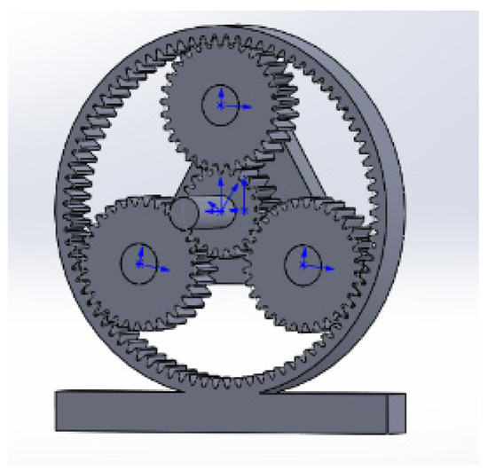
Figure 1.
Complete assembly model.

Figure 2.
Fault model diagram for each included tooth construction: (a) Sun gear missing teeth; teeth; (b) Planetary gear missing teeth; (c) Planetary gear pitting.
In this paper, ADAMS and MATLAB were selected as the joint simulation platform for the digital twin. In the ADAMS multi-body dynamics modeling environment, the part model in X_T format or the part assembly constraints in ADAMS format was read, the properties of the part entities were modified, the new part coordinate systems were added to connect other entities and constraints, and the contact forces and torques in the model were defined. The modification and addition of kinematic pairs according to the actual application purpose could then be enacted to realistically reflect the actual connection relationship between the planetary gearbox components. The physical properties of the kinematic subsets, such as stiffness and damping, and the friction coefficient were also defined. The physical entities were structural steel and the contact forces were simulated using the IMPACT function. Considering that the pure rigid body dynamics simulation can only simulate the dynamics map of the model’s center of mass, and cannot extract accurate fault information, it was necessary to introduce a flexible body, and to consider the placement of the sensors so the ring gear is flexible in this paper, in order to better transfer the gear vibration information and allow the sensors to collect data better. In this paper, we use ANSYS APDL software (ANSYS APDL 2020R2) to make the ring gear flexible, import it into ADMAS in MNF file format, replace the original rigid body model, and finally, obtain a rigid-flexible coupled multi-body dynamics model with both rigid and flexible bodies. The rigid-flexible coupled multi-body dynamics model is shown in Figure 3.
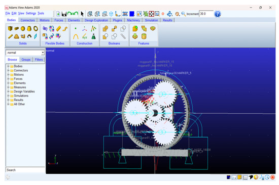
Figure 3.
Rigid-flexible coupling multi-body dynamics model.
We then set up the speed input, the displacement output of the X and Y directions of the ring gear, and the speed output of the X and Y directions, respectively. After setting up in ADAMS, we exported the setup model to MATLAB, as shown in Figure 4 below, and built the motor model in MATLAB, using the PMSM motor module and the Universal Bridge module in MATLAB Simulink. We set the specific parameters in the motor model according to the actual parameters of the test bench motor, and used the STEP function to simulate a process change in the motor from standstill to acceleration. The motor model outputs a speed signal into the planetary gearbox module in radians. The motor module diagram is shown in Figure 5 below. The set motor module was connected with the planetary gear module, and finally, the digital twin model of the planetary gearbox was formed, as shown in Figure 6 below.
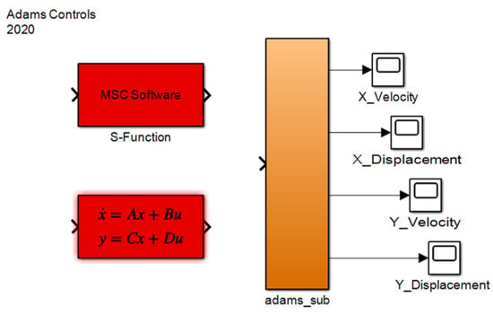
Figure 4.
ADAMS output model.
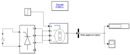
Figure 5.
Motor driver model.
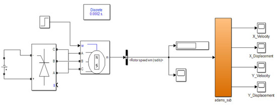
Figure 6.
Digital twin model of planetary gearbox.
3. Analysis of Planetary Gearbox Vibration Characteristics
The original signal measured on the gearbox is usually a complex composition of one or several vibration signals superimposed with structural frequencies. If the cross-modulation component is ignored, the gearbox vibration signal can be expressed in Equation (1), which is taken from [24], as follows:
where
- is the vibration signal at each rotation frequency in Equation (1).
- is the gear meshing frequency modulation signal.
- is the modulated signal of each order of the gear’s intrinsic frequency.
- is the modulated signal of the intrinsic frequency of the gearbox.
- is the bearing vibration signal.
- represents the other vibration disturbance signals.
- is the carrier signal.
- is the modulated signal.
From Equation (1), it can be seen that when a fault occurs in a gear system, in addition to the gear mesh frequency and its respective harmonics, the modulation of the signal appears in the spectrum: modulation with the gear mesh frequency and its respective harmonics as carriers, resonance modulation with the intrinsic frequency of the gear as a carrier or with the intrinsic frequency of the box as a carrier [40]. In the real operating environment of the entity corresponding to the digital twin, amplitude modulation and phase modulation coexist, and the effect is expressed in the time domain curve and the spectrogram, respectively.
Planetary Gearbox Vibration Characteristic Frequency
For planetary gearboxes, the characteristic frequency of gear faults depends on the specific structural parameters and rotational speed of the gearbox. In single-stage planetary gearboxes, the gear meshing frequencies of the two meshing pairs, the sun gear and the planet gear, and the planet gear, and the ring gear are the same. Usually, the ring gear is fixed and the sun gear, planet gear, and planetary carrier rotate, in which case the meshing frequency is [41]
In Equation (2), and are the number of teeth of the ring gear and the sun gear, respectively; is the absolute rotation frequency of the sun gear.
Local fault in the gear will cause shock vibration. For planetary gearboxes, the characteristic frequency of local faults in the gear depends not only on the speed of the gearbox, but also on the number of teeth of the sun gear, planetary gear, and ring gear, and the number of planetary gears.
If there is a local fault in the sun gear, the faulty gear will mesh with all planetary gears during one rotation cycle relative to the planetary frame and produce shocks, so the characteristic frequency of local faults in the sun gear is
In Equation (3), is the number of sun gear teeth and N is the number of planetary gears.
If there is a local fault in the planetary gear, the faulty gear meshes with both the sun gear and the ring gear during one rotation cycle relative to the ring gear, generating a shock, so the characteristic frequency of the local fault in the planetary gear is
In Equation (4), is the number of ring gear teeth.
4. Planetary Gearbox Digital Twin Model Simulation Analysis
The simulation platform used in this section was MATLAB. The basic parameters of the simulated gear are shown in Table 2. The simulation motor drive speed was set to 1800 rpm, the simulation time was 4 s, and the step size was 0.0002 s. According to the structural parameters of the gearbox and the speed, the characteristic frequency of the gear local fault was calculated and is shown in Table 2.

Table 2.
Simulation of planetary gearbox characteristic frequency.
4.1. Simulation Analysis of Normal Working Condition of Sun Gear and Planetary Gear
The simulation model was set up according to the above parameters, and the sensor measurement point was set up at the point directly above the ring gear, where the vibration velocity signal in the Y direction of the ring gear was used, and then the simulation data were processed in MATLAB with a sampling frequency of 5000 Hz, and the Hilbert transform was performed on the time domain spectrum, and the final obtained time domain waveform and frequency spectrum are shown in Figure 7 below. The spectrum was taken between 450 Hz and 550 Hz.
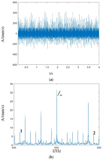
Figure 7.
Normal simulation vibration signal of sun gear and planetary gear: (a) Time domain waveform; (b) Fourier spectrum.
Figure 7 shows the time domain waveform and the Fourier spectrum of the planetary gearbox vibration signal under normal conditions. The time domain waveform is uniformly distributed as a whole, without any obvious evidence of shock. 1 and 2 in the figure are and , respectively. It can be seen from the Fourier spectrum that shocks with frequencies of (n = 1,2,…) appear in the sideband of the meshing cycle, and the sideband is spaced at the planetary frame rotation frequency. These phenomena indicate that the passing effect of the planetary gear plays a major role in amplitude modulation of the meshing vibration, which is in line with the theoretical expectation of the normal planetary gearbox vibration signal, and also basically in line with the results of the subsequent experimental verification.
4.2. Simulation Analysis of the Combined Fault Conditions of Sun Gear Missing Teeth and Planetary Gear Pitting
The simulation model was also set up according to the above parameters, the sampling frequency was kept constant, the simulation data were imported into MATLAB for processing, and then the Hilbert transform was performed on the time domain spectrum, and the final time domain waveform and spectrum are shown in Figure 8 below.
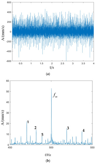
Figure 8.
Simulated vibration signal of sun gear missing teeth and planetary gear pitting: (a) Time domain waveform; (b) Fourier spectrum.
Figure 8 shows the time domain waveform and Fourier frequencies of the combined fault vibration signal of the sun gear missing teeth and planetary gear pitting. In the time domain waveform, more obvious evidence of shock appears, and more modulation frequencies appear in the Fourier spectrum. For easy identification, only the meshing frequency and the modulation frequency associated with the fault are marked in the figure. Due to the modulation effect caused by the planetary frame and sun gear self-propagation, the sideband interval and its multiplicative correlation modulation sideband appear on both sides of . For example, at point 5 is . Moreover, due to the presence of three planetary gears, it can be seen in the figure that peaks occur at the positions of the meshing frequency, and the sideband is spaced as times the characteristic frequency of the sun gear fault, where n is an integer, 1 is . Peaks appear at the positions , related to the characteristic frequency associated with the planetary gear, where n is an integer, such that 2, 3, and 4 would be , , and , respectively, so the comprehensive diagnosis is that both the sun gear and the planetary gear are faulty.
4.3. Simulation Analysis of Combination Fault of Sun Gear Missing Teeth and Planetary Gear Missing Teeth
Figure 9 shows the time domain waveform and Fourier frequencies of the combined fault vibration signals of the sun gear missing teeth and the planetary gear missing teeth. Compared with the case of the sun gear missing teeth and the planetary gear pitting, there is a more obvious shock in the time domain waveform when the sun gear and the planetary gear are missing teeth at the same time, and the frequency modulation of the whole Fourier spectrum is more obvious. Similarly, due to the modulation effect caused by the planetary frame at both sides of the meshing frequency , the sideband appears on both sides of with a sideband interval of , such that 4 and 5 would be and , respectively. Due to the presence of three planetary gears, it can also be seen in the figure that peaks at positions such as the meshing frequency with the sideband spaced at times the characteristic frequency of the sun gear fault, where n is an integer, such that 1, 3, 7, and 8 would be , , , and , respectively. Peaks are found at the positions of frequency associated with the planetary gear fault characteristic frequency , where n is an integer, such that at 2 and 6 are and , respectively. Therefore, the comprehensive diagnosis is that both the sun gear and the planetary gear are faulty.
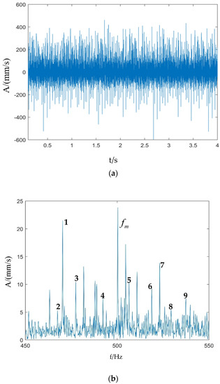
Figure 9.
Simulated vibration signal of sun gear missing teeth and planetary gear missing teeth: (a) Time domain waveform; (b) Fourier spectrum.
5. Experimental Verification of Different Combinations of Fault Conditions
The faulty gear is shown in Figure 10. The experimental bench is shown in Figure 11 below. The acceleration sensor was placed directly above the planetary gearbox. The experimental motor speed was set to 1800 rpm, the actual speed was 1782 rpm, the sampling frequency was 5000 Hz, the sampling time was 4s, and the actual rotation frequency of the sun gear was 29.7 Hz. The gear-related parameters and the characteristic frequency of the gearbox are given in Table 3 and Table 4 below. The frequency was taken between 450 Hz and 550 Hz.
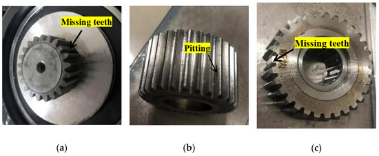
Figure 10.
Sun gear and planetary gear missing teeth and planetary gear pitting fault: (a) Sun gear missing teeth; (b) Planetary gear pitting; (c) Planetary gear missing teeth.
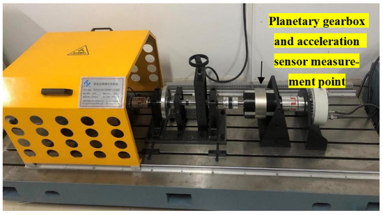
Figure 11.
Integrated fault simulation test bench.

Table 3.
Gear parameters used in the experiment.

Table 4.
Experiment of planetary gearbox characteristic frequency.
5.1. Experimental Verification of Normal Working Conditions of Sun Gear and Planetary Gear
Figure 12 shows the time domain waveform and Fourier frequencies of the vibration signals under the normal operating conditions of both the sun gear and the planetary gear. The time domain waveform is uniformly distributed as a whole without obvious shocks, and the Fourier spectrum is at the position where the sideband of the meshing cycle appears at a frequency of (n = 1,2,…), and the sideband interval is the rotation frequency of the planetary frame, as shown in the figure at points 1 and 2, which are and , respectively, and these phenomena are consistent with the theoretical expectations of the normal planetary gearbox vibration signal and are basically consistent with the simulation in the previous section, which verifies the correctness of the simulation model and the credibility of the results.
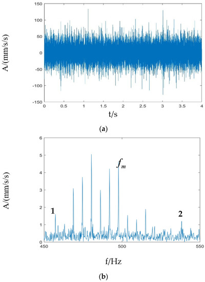
Figure 12.
Experimental vibration signal of sun gear and planetary gear under normal working conditions: (a) Time domain waveform; (b) Fourier spectrum.
5.2. Experimental Verification of the Combined Fault Conditions of Sun Gear Missing Teeth and Planetary Gear Pitting
Figure 13 shows the time domain waveform and the Fourier spectrum of the experimental vibration signal under the combined fault conditions of the sun gear teeth missing and planetary gear pitting. The time domain waveform shows a more obvious shock, and the peak of the whole spectrum is more obvious. There is a modulation effect of the planetary frame on the meshing frequency, so there are peaks at on both sides of the meshing frequency , where n is an integer, such that 6, 9 and 7, 8 are and , respectively. Due to the presence of three planetary gears, it can also be seen in the figure that peaks appear at the positions of the meshing frequency, with sideband intervals of times the characteristic frequencies of the sun gear fault, where n is an integer, such that 1, 3, 4, 11, 12, and 13 are , , , , , and , respectively. Peaks are found at the positions of frequency associated with the planetary gear fault characteristic frequency , such as at 2, 5, and 10 are , , and , respectively, and it can be seen that the experimental signal is basically consistent with the simulated signal. Therefore, the comprehensive diagnosis is that both the sun gear and the planetary gear are faulty.
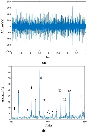
Figure 13.
Vibration signal of sun gear missing teeth and planetary gear pitting experiment: (a) Time domain waveform; (b) Fourier spectrum.
5.3. Experimental Verification of the Combined Fault Conditionsof Sun Gear Missing Teeth and Planetary Gear Missing Teeth
From Figure 14, it can be seen that the time domain waveform shock is more obvious when the sun gear and planetary gear are missing teeth at the same time. Similarly, peaks on both sides of the meshing frequency , where n is an integer, such as at 3 and 4 are , respectively. Due to the existence of three planetary gears, it can be seen in the figure that peaks appear at the positions of meshing frequency with a sideband interval of times the characteristic frequency of the sun gear fault, where n is an integer. For example, at 2, 6, and 7 are , , and , respectively. Peaks are found at the positions of frequency associated with the planetary gear fault characteristic frequency , such that 1, 5, 8, and 9 are , , , and , respectively. The experimental signal is basically consistent with the simulated signal. Therefore, the comprehensive diagnosis is that both the sun gear and planetary gear are faulty.
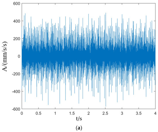
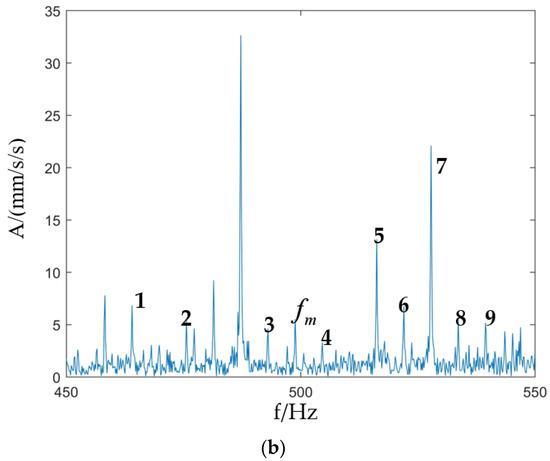
Figure 14.
Vibration signal of the sun gear missing teeth and planetary gear missing teeth experiment: (a) Time domain waveform; (b) Fourier spectrum.
From the experiment, it can be seen that when both the sun gear and the planetary gear are faulty, the spectrum peaks are more intensive compared with normal operating conditions. Although the types of fault combinations are different, they are all faulty for the planetary gearbox system, so the spectrum peaks are roughly the same in terms of distribution. In addition, there are manufacturing errors and assembly errors in the test bench, which lead to the appearance of an interference spectrum in the experimental signal, but it can still be found that the frequency distribution of the model signal is basically consistent with the test through the comparison between the simulation and the test, and the frequency spectrum is mostly distributed around the engagement frequency, thus verifying the accuracy of the digital twin model. The accuracy of the digital twin model is verified, and it provides a theoretical basis for the health monitoring and fault diagnosis of the planetary gearbox system.
6. Comparative Research
When a gear fault occurs, it produces a significant shock, and the response amplitude of the fault location becomes larger as the fault degree increases. In order to further reflect the advantages of digital twin modeling, the traditional modeling method and digital twin modeling method were compared and analyzed, and the root-mean-square was used as an example to analyze the changes in the root-mean-square index throughout the development of the fault. Taking the evolution of the sun gear missing teeth fault as an example, the missing teeth degradation process was modeled conventionally and digitally twinned, respectively, and the gear parameters and simulation settings were the same as in the previous section. The changes in the statistical indicators of the root-mean-square values under different modeling methods are shown in Figure 15.
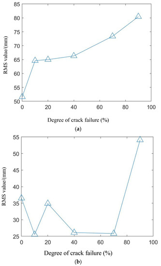
Figure 15.
Comparison of the two models: (a) Root-mean-square value of the digital twin model; (b) Root-mean-square value of the traditional model.
From Figure 15, it can be seen that the root-mean-square indicator shows an increasing trend with the increase in the fault degree, and the root-mean-square indicator is very sensitive to the fault. The comparison of the two models shows that the root-mean-square indicator of the digital twin model is better than the traditional model and better reflects the fault evolution trend.
7. Conclusions
In this paper, the digital twin technique was used to investigate the vibration spectrum characteristics of planetary gearboxes. The physical model of the system vibration was constructed and the characteristic frequency of the system fault was calculated taking into consideration that the planetary gearbox system is prone to faults. A digital twin model of the planetary gearbox structure was established with reference to the existing primary planetary gearbox test bench in the laboratory. Firstly, a combined fault model of the sun gear and planetary gear was built in SOLIDWORKS, and then a rigid-flexible coupled multi-body dynamic model was built in ADAMS, which was close to the actual operating state of the physical object. Then, the model was imported into MATLAB, and the electrical model was built using the motor module that comes with Simulink. Finally, each module was connected to form the digital twin model of the planetary gearbox. The sun gear fault frequency and planetary gear fault frequency appear in the experiment, similarly, the sun gear fault frequency and planetary gear failure frequency appear in the simulation. Through the comparison of the experiment and simulation results, it was verified that the digital twin model can accurately simulate the motion state of the physical object and still has good accuracy even under multi-fault working conditions. Meanwhile, according to the root-mean-square metrics used to characterize the faults, the root-mean-square characteristic metrics of the digital twin model are better than the root-mean-square index of the traditional model. In the future, based on this model, the predictive maintenance of planetary gear can be studied to provide a solution to the problem of obtaining data during the degradation process of actual gear equipment. At the same time, through the ideas of positive derivation and inverse identification, accurate meshing parameters, transmission errors, and other mechanical parameters during the fault evolution can be obtained, based on which a more realistic digital twin gear degradation model can be established as a substitute for partial experiments. This research can be applied in the aerospace and automotive fields, and in large-scale industrial equipment to provide solutions for fault diagnosis and predictive maintenance in the above fields.
Author Contributions
Conceptualization, D.Z. and Z.L.; methodology, D.Z.; software, D.Z.; validation, D.Z., N.H. and Z.L.; formal analysis, N.H.; data curation, D.Z.; writing—original draft preparation, D.Z.; writing—review and editing, Z.L. and N.H.; visualization, Z.L.; supervision, Z.L.; funding acquisition, Z.L., N.H. All authors have read and agreed to the published version of the manuscript.
Funding
This work supported by the grant from National Natural Science Foundation of China (Grant No. 51975576), National Key R and D Program of China (Grant No.2018YFB1702401), Key projects of Natural Science Foundation of Jiangxi Province (Grant No. 20212ACB202005), and Postgraduate Innovation Special Fund of Jiangxi Province (Grant No. YC2021-S692).
Institutional Review Board Statement
Not applicable.
Informed Consent Statement
Not applicable.
Data Availability Statement
Not applicable.
Conflicts of Interest
The authors declare no conflict of interest.
References
- Adam, M.; Mariusz, S.; Piotr, P. Graphical method for the analysis of planetary gear trains. Alex. Eng. J. 2022, 61, 4067–4079. [Google Scholar]
- Peng, D.; Zuo, S.; Liu, T.; Xu, X.; Guo, W.; Liu, Y.; Wu, H.; Wang, S. A matrix-based method for searching configurations of planetary gear trains. Mech. Mach. Theory 2023, 180, 105161. [Google Scholar] [CrossRef]
- Figlus, T.; Kozioł, M.; Kuczyński, Ł. The Effect of Selected Operational Factors on the Vibroactivity of Upper Gearbox Housings Made of Composite Materials. Sensors 2019, 19, 4240. [Google Scholar] [CrossRef]
- Figlus, T.; Kozioł, M.; Kuczyński, Ł. Impact of Application of Selected Composite Materials on the Weight and Vibroactivity of the Upper Gearbox Housing. Materials 2019, 12, 2517. [Google Scholar] [CrossRef] [PubMed]
- Wojnar, G.; Burdzik, R.; Wieczorek, A.N.; Konieczny, Ł. Multidimensional Data Interpretation of Vibration Signals Registered in Different Locations for System Condition Monitoring of a Three-Stage Gear Transmission Operating under Difficult Conditions. Sensors 2021, 21, 7808. [Google Scholar] [CrossRef] [PubMed]
- Amer, W.S. On the motion of a flywheel in the presence of attracting center. Results Phys. 2017, 7, 1214–1220. [Google Scholar] [CrossRef]
- Amer, T.S.; Farag, A.M.; Amer, W.S. The dynamical motion of a rigid body for the case of ellipsoid inertia close to ellipsoid of rotation. Mech. Res. Commun. 2020, 108, 103583. [Google Scholar] [CrossRef]
- Brumercik, F.; Lukac, M.; Caban, J.; Krzysiak, Z.; Glowacz, A. Comparison of Selected Parameters of a Planetary Gearbox with Involute and Convex–Concave Teeth Flank Profiles. Appl. Sci. 2020, 10, 1417. [Google Scholar] [CrossRef]
- Zou, H.; Wang, S.; Li, F.; Liu, L.; Li, L.; Li, Z. Improved algorithm of tooth surface topological modification and nonlinear dynamic analysis of herringbone gears. Mech. Mach. Theory 2023, 180, 105151. [Google Scholar] [CrossRef]
- Ma, R.; Chen, Y. Research on the dynamic mechanism of the gear system with local crack and spalling failure. Eng. Fail. Anal. 2021, 26, 12–20. [Google Scholar] [CrossRef]
- Ma, R.; Chen, Y.; Cao, Q. Research on dynamics and fault mechanism of spur gear pair with spalling defect. J. Sound Vib. 2012, 331, 2097–2109. [Google Scholar] [CrossRef]
- Wang, X.; Wu, X.; Xiao, Z.; Cao, Y. Dynamic characteristics of a gear system with crack fault and its fault feature analysis. J. Vib. Shock 2017, 36, 74–79,137. [Google Scholar]
- Shix, J.; Li, K.; Wang, Z.M. Fault simulation and modeling of wind turbine gear based on ADAMS. In Proceedings of the 2016 IEEE International Conference on Information and Automation (ICIA), Ningbo, China, 1–3 August 2016; IEEE: Toulouse, France, 2016. [Google Scholar]
- Lei, Y.; Luo, X.; Liu, Z. A New Dynamic Model of Planetary Gear Sets and Research on Fault Response Characteristics. J. Mech. Eng. 2016, 52, 111–122. [Google Scholar] [CrossRef]
- Feng, Z.; Chu, F. Vibration spectral characteristics of distributed gear fault of planetary gearboxes. Proc. CSEE 2013, 33(02), 118–125. [Google Scholar]
- Feng, Z.; Zhao, L.; Chu, F. Vibration spectral characteristics of localized gear fault of planetary gearboxes. Proc. CSEE 2013, 33(05), 119–127. [Google Scholar]
- Inalpolat, M.; Handschuh, M.; Kahraman, A. Influence of indexing errors on dynamic response of spur gear pairs. Mech. Syst. Signal Process. 2015, 60–61, 391–405. [Google Scholar] [CrossRef]
- Dong, H.; Zhang, C.; Wang, D.; Xu, S.; Qiu, J. Dynamic characteristics of gear box with PGT for wind turbine. Procedia Comput. Sci. 2017, 109, 801–808. [Google Scholar] [CrossRef]
- Wang, R.-M.; Gao, Z.-Y.; Wang, W.-R.; Xue, Y.; Fu, D.-Y. Dynamic characteristics of the planetary gear train excited by time-varying meshing stiffness in the wind turbine. Int. J. Miner. Metall. Mater. 2018, 25, 1104–1112. [Google Scholar] [CrossRef]
- Parra, J.; Vicunac, M. Two methods for modeling vibrations of planetary gearbox including faults: Comparison and validation. Mech. Syst. Signal Process. 2017, 92, 213–225. [Google Scholar] [CrossRef]
- Chen, H.; Hu, N.; Cheng, Z.; Zhang, L.; Zhang, Y. A deep convolutional neural network based fusion method of two-direction vibration signal data for health state identification of planetary gearbox. Measurement 2019, 146, 268–278. [Google Scholar] [CrossRef]
- Gil, L.; Przystupa, K.; Pieniak, D.; Kozłowski, E.; Antosz, K.; Gauda, K.; Izdebski, P. Influence of Contamination of Gear Oils in Relation to Time of Operation on Their Lubricity. Appl. Sci. 2021, 11, 11835. [Google Scholar] [CrossRef]
- Rong, K.; Ding, H.; Kong, X.; Huang, R.; Tang, J. Digital twin modeling for loaded contact pattern-based grinding of spiral bevel gears. Adv. Eng. Inform. 2021, 49, 101305. [Google Scholar] [CrossRef]
- Pang, Y. Simulation Study on Dynamics and Fault Diagnosis of Digital Twin in Planetary Gearbox. Master’s Thesis, North University of China, Taiyuan, China, 2020. [Google Scholar]
- Moghadam, F.K.; Nejad, A.R. Online condition monitoring of floating wind turbines drivetrain by means of digital twin. Mech. Syst. Signal Process. 2022, 162, 108087. [Google Scholar] [CrossRef]
- Moghadam, F.K.; Rebouças, G.F.d.S.; Nejad, A.R. Digital twin modeling for predictive maintenance of gearbox in floating offshore wind turbine drivetrains. Forsch. Ingenieurwesen. 2021, 85, 273–286. [Google Scholar] [CrossRef]
- Olatunji, O.; Adedeji, P.A.; Madushele, N.; Jen, T.-C. Overview of Digital Twin Technology in Wind Turbine Fault Diagnosis and Condition Monitoring. In Proceedings of the 2021 IEEE 12th International Conference on Mechanical and Intelligent Manufacturing Technologies (ICMIMT), Cape Town, South Africa, 13–15 May 2021; pp. 201–207. [Google Scholar]
- Nguyen, T.N.; Ponciroli, R.; Bruck, P.; Esselman, T.C.; Rigatti, J.A.; Vilim, R.B. A digital twin approach to system-level fault detection and diagnosis for improved equipment health monitoring. Ann. Nucl. Energy 2022, 170, 109002. [Google Scholar] [CrossRef]
- Ayo-Imoru, R.M.; Ali, A.A.; Bokoro, P.N. An enhanced fault diagnosis in nuclear power plants for a digital twin framework, 2021 International Conference on Electrical. In Proceedings of the 2021 International Conference on Electrical, Computer and Energy Technologies, Cape Town, South Africa, 9–10 December 2021; pp. 1–6. [Google Scholar]
- Hosamo, H.; Svennevig, P.R.; Svidt, K.; Han, D.; Nielsen, H.K. A Digital Twin predictive maintenance framework of air handling units based on automatic fault detection and diagnostics. Energy Build. 2022, 261, 111988. [Google Scholar] [CrossRef]
- Jain, P.; Poon, J.; Singh, J.P.; Spanos, C.; Sanders, S.R.; Panda, S.K. A Digital Twin Approach for Fault Diagnosis in Distributed Photovoltaic Systems. IEEE Trans. Power Electron. 2019, 35, 940–956. [Google Scholar] [CrossRef]
- Giannaros, E.; Kotzakolios, A.; Kostopoulos, V.; Sotiriadis, G.; Vignjevic, R.; Djordjevic, N.; Boccaccio, M.; Meo, M. Low- and high-fidelity modeling of sandwich-structured composite response to bird strike, as tools for a digital-twin-assisted damage diagnosis. Int. J. Impact Eng. 2022, 160, 104058. [Google Scholar] [CrossRef]
- Kerman, L.d.C.-E.; Eider, G.-P.; Aitor, A. Towards a Circular Rotating Blade Wear Assessment Digital Twin for Manufacturing Lines. IFAC-Pap. Line 2022, 55, 561–566. [Google Scholar] [CrossRef]
- Sleiti, A.K.; Kapat, J.S.; Vesely, L. Digital twin in energy industry: Proposed robust digital twin for power plant and other complex capital-intensive large engineering systems. Energy Rep. 2022, 8, 3704–3726. [Google Scholar] [CrossRef]
- Suhail, S.; Malik, S.U.R.; Jurdak, R.; Hussain, R.; Matulevičius, R.; Svetinovic, D. Towards situational aware cyber-physical systems: A security-enhancing use case of blockchain-based digital twins. Comput. Ind. 2022, 141, 103699. [Google Scholar] [CrossRef]
- Zipper, H. Real-Time-Capable Synchronization of Digital Twins. IFAC-Pap. Line 2021, 54, 147–152. [Google Scholar] [CrossRef]
- Lopes, T.D.; Raizer, A.; Junior, W.V. The Use of Digital Twins in Finite Element for the Study of Induction Motors Faults. Natl. Counc. Sci. Technol. Dev. 2022, 21, 7833. [Google Scholar] [CrossRef]
- Turan, E.; Konuşkan, Y.; Yıldırım, N.; Tunçalp, D.; İnan, M.; Yasin, O.; Turan, B.; Kerimoğlu, V. Digital twin modelling for optimizing the material consumption: A case study on sustainability improvement of thermoforming process. Sustain. Comput. Inform. Syst. 2022, 35, 100655. [Google Scholar] [CrossRef]
- Teethman, M.; Braun, B.; Bury, S.J.; Dessauer, M.; Henderson, K.; Phillips, S.; Ye, Y.; Tilbury, D.M.; Moyne, J.; Barton, K. A Digital Twin Framework for Mechanical System Health State Estimation. IFAC-Pap. Line 2021, 54, 1–7. [Google Scholar] [CrossRef]
- Li, X.; Feng, Z. Vibration spectral features of planetary gearbox combined faults. J. Vib. Shock 2020, 39, 15–23. [Google Scholar]
- Wang, Y.; Tao, F.; Zhang, M.; Wang, L.; Zuo, Y. Digital twin enhanced fault prediction for the autoclave with insufficient data. J. Manuf. Syst. 2021, 60, 350–359. [Google Scholar] [CrossRef]
Publisher’s Note: MDPI stays neutral with regard to jurisdictional claims in published maps and institutional affiliations. |
© 2022 by the authors. Licensee MDPI, Basel, Switzerland. This article is an open access article distributed under the terms and conditions of the Creative Commons Attribution (CC BY) license (https://creativecommons.org/licenses/by/4.0/).