Article

Real-Time Stereo Visual Odometry Based on an Improved KLT Method

1
Shanghai Institute of Technical Physics, Chinese Academy of Sciences, Shanghai 200083, China
2
University of Chinese Academy of Sciences, Beijing 100049, China
*
Author to whom correspondence should be addressed.
Appl. Sci. 2022, 12(23), 12124; https://doi.org/10.3390/app122312124
Submission received: 26 October 2022 / Revised: 23 November 2022 / Accepted: 24 November 2022 / Published: 27 November 2022
(This article belongs to the Special Issue Trajectory Analysis, Positioning and Control of Mobile Robots)

Abstract

:
Real-time stereo visual odometry (SVO) localization is a challenging problem, especially for a mobile platform without parallel computing capability. A possible solution is to reduce the computational complexity of SVO using a Kanade–Lucas–Tomasi (KLT) feature tracker. However, the standard KLT is susceptible to scale distortion and affine transformation. Therefore, this work presents a novel SVO algorithm yielding robust and real-time localization based on an improved KLT method. First, in order to improve real-time performance, feature inheritance is applied to avoid time-consuming feature detection and matching processes as much as possible. Furthermore, a joint adaptive function with respect to the average disparity, translation velocity, and yaw angle is proposed to determine a suitable window size for the adaptive KLT tracker. Then, combining the standard KLT method with an epipolar constraint, a simplified KLT matcher is introduced to substitute feature-based stereo matching. Additionally, an effective veer chain matching scheme is employed to reduce the drift error. Comparative experiments on the KITTI odometry benchmark show that the proposed method achieves significant improvement in terms of time performance than the state-of-the-art single-thread approaches and strikes a better trade-off between efficiency and accuracy than the parallel SVO or multi-threaded SLAM.

1. Introduction

As an essential simultaneous localization and mapping (SLAM) front end, visual odometry (VO) has been developed over the past decades [1]. The VO fundamental is incrementally estimating the rotational and translational changes of consecutive image frames [2]. Since monocular VO cannot determine the scale information of motion, stereo VO (SVO) with an extra camera means that depth information is available through triangulation of a well-calibrated stereo rig. Although existing methods can provide very accurate and robust trajectory estimates with a relative position error better than 2% [3], their practical usage is limited because of the computational burden. For instance, SOFT2 [4] accomplished the optimal performance on the KITTI leaderboard in terms of rotational and translational accuracy thus far, while the processing speed was only 10 Hz on a 2.5 GHz CPU with four cores.
Currently, this challenging problem has been extensively studied in VO work. Most SVO methods typically consist of feature detection, stereo matching, feature tracking, and motion estimation [5]. In general, improvements in time performance can be divided into three groups. First, since one of the main reasons for the aforementioned problem is that the feature detector and robust motion estimator tend to take most of the SVO time, as reported in [6], real-time SVO can be achieved by employing a more compact feature detector or motion estimator. With a much simpler Sobel filter as the feature detector, the work in [7] developed a real-time SVO at a minimum computational complexity using the KITTI odometry dataset. Although their system is able to run at 0.05 s per frame on a single CPU core @ 2.5 GHz, the simplified detector and matcher are susceptible to scale distortion or affine transformation. Second, given prior knowledge of ego-motion from other systems, such as an inertial measurement unit and wheel encoder-based odometry [8,9,10], the range of searching for features and matching can be greatly reduced. However, this method is prone to a large error accumulation, especially for vehicles losing traction on large rocks and steep slopes [9,10]. Another common solution is parallelization through multithread programming [11], FPGA, or GPU acceleration [12,13]. The four-thread architecture of OV2SLAM [14] can run at 200 Hz on a 3.0 GHz CPU with eight cores. A real-time SVO that relies on heavy parallelism can limit its applications in mobile vehicles [7]. Therefore, the main purpose of this work was to develop a single-thread SVO without any prior knowledge of the motion to produce real-time and robust localization on a standard CPU.
According to the publicly available KITTI leaderboard, the fast and robust visual odometry (FRVO) in [6] exceeds all other validated methods in real-time performance. In their implementation, a pruning corner detector and an improved Kanade–Lucas–Tomasi (KLT) tracker are able to reduce the computational complexity of SVO. The speed of FRVO is 0.03 s per frame on a 3.5 GHz CPU, with an average translation error of 1.26% and a rotation error of 0.0038 deg/m. However, to determine a suitable window size for the KLT tracker, FRVO requires a dense disparity map to be provided beforehand and the abovementioned time performance does not include the time for a dense disparity computation, which is usually a time-consuming process. In this paper, the proposed approach achieves better real-time performance on a lower-speed processor with similar localization accuracy. Instead of the three improvements mentioned above, a new approach is proposed to reduce computational complexity through both feature inheritance (FI) and an improved KLT method. The KLT improvements include an adaptive KLT tracker (AKT) and a simplified KLT matcher (SKM). The proposed approach is most similar to the SVO in [15]. A KLT tracker [16] is also used in a similar way to avoid both feature detection and matching in a new frame, but with several important distinctions that are summarized in the following steps:
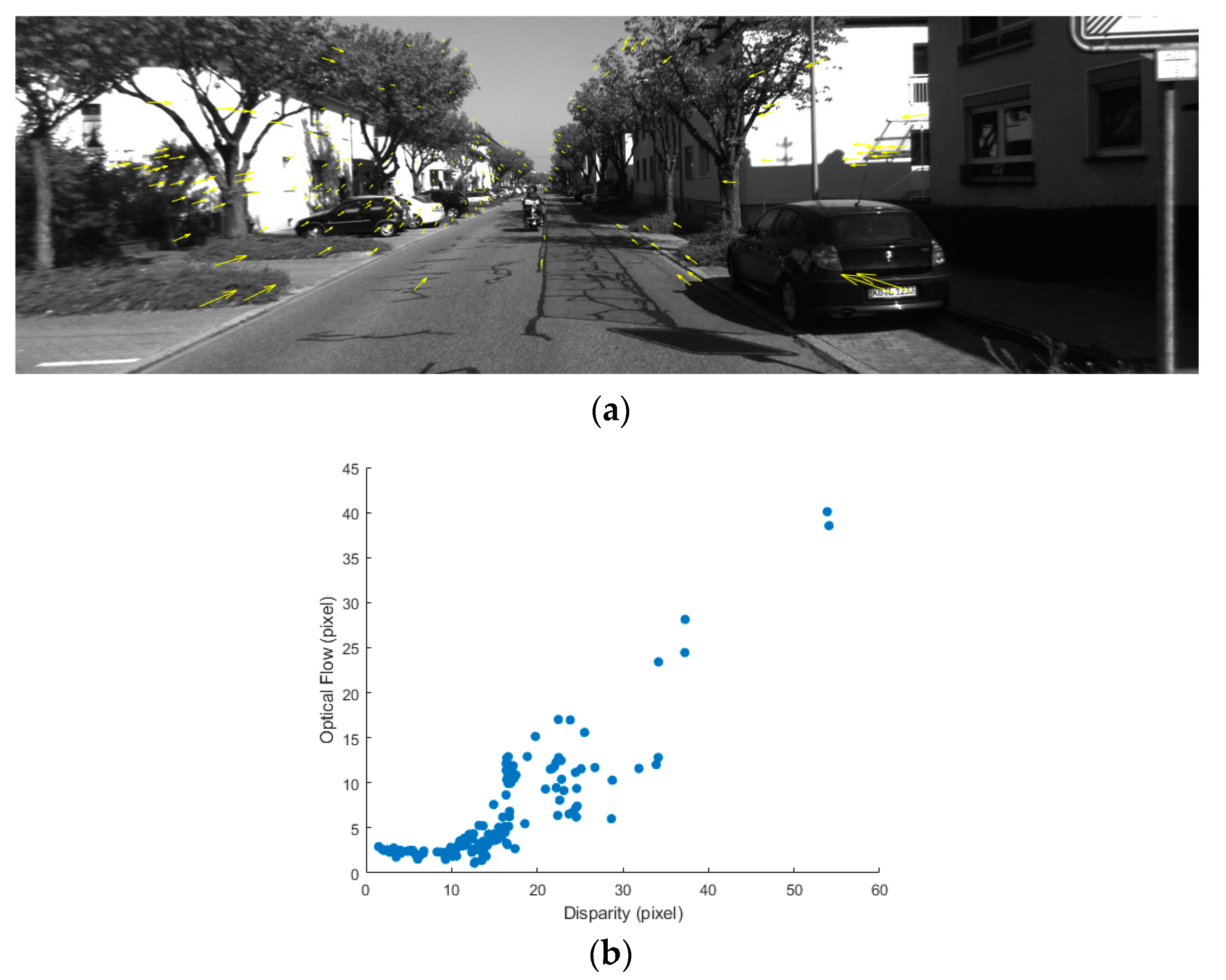
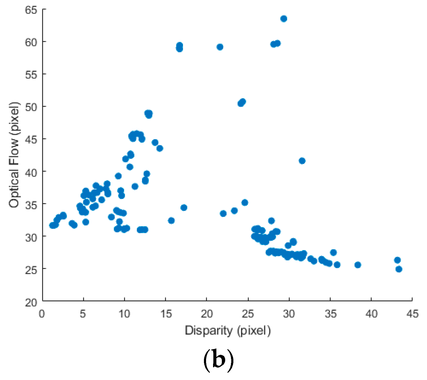
  • By analyzing the relationship between the motion experienced by the feature, the average disparity, the translation velocity, the yaw angle, and the adaptive window size for the AKT must by necessity be jointly determined, which can significantly improve the tracking accuracy in the presence of scale distortion and affine transformation.
  • The AKT tracks the inherited features between only the left images of two consecutive frames, and the SKM is performed in a new stereo frame, which can avoid computationally expensive feature detection and feature-based stereo matching processes as much as possible.
  • To limit the drift error, an effective veer chain matching (VCM) scheme is introduced.
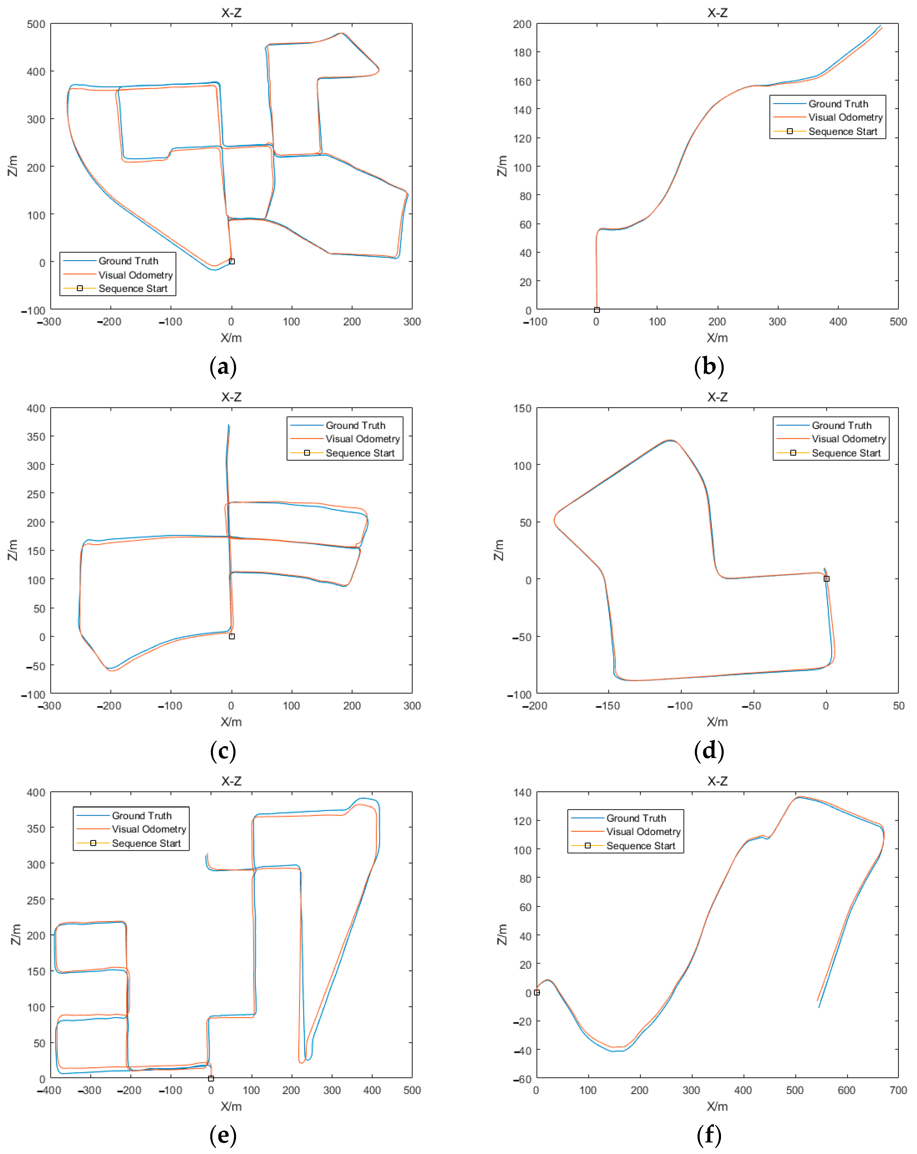
  • A systematic evaluation using the KITTI dataset [17] was performed. The experimental results show that the proposed SVO can achieve better real-time performance in comparison to the other state-of-the-art approaches without deteriorating the localization accuracy.
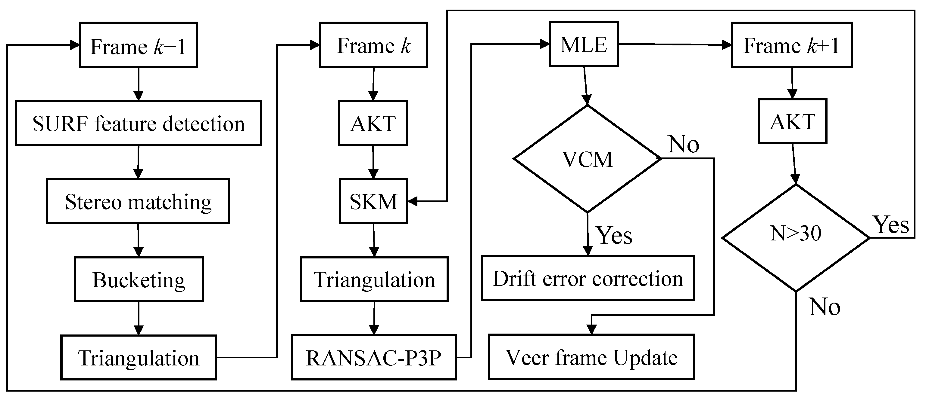
The rest of the paper is organized as follows. Section 2 concisely outlines the proposed SVO, which is explained in detail in Section 3. Section 4 outlines several comparative experiments that were conducted to demonstrate the effectiveness of the proposed approach, and the conclusions are made in Section 5.

2. Method Overview

Figure 1 depicts the workflow of the proposed SVO which can be outlined in the following steps:
  • Searching for a series of SURF key points in the first stereo frame and computing their normalized descriptors with 64 dimensions.
  • With the epipolar constraint, stereo matching is performed using the Euclidean distance between the SURF descriptors.
  • A subset of the matched features is selected by means of bucketing to ensure the features are uniformly distributed over the image plane.
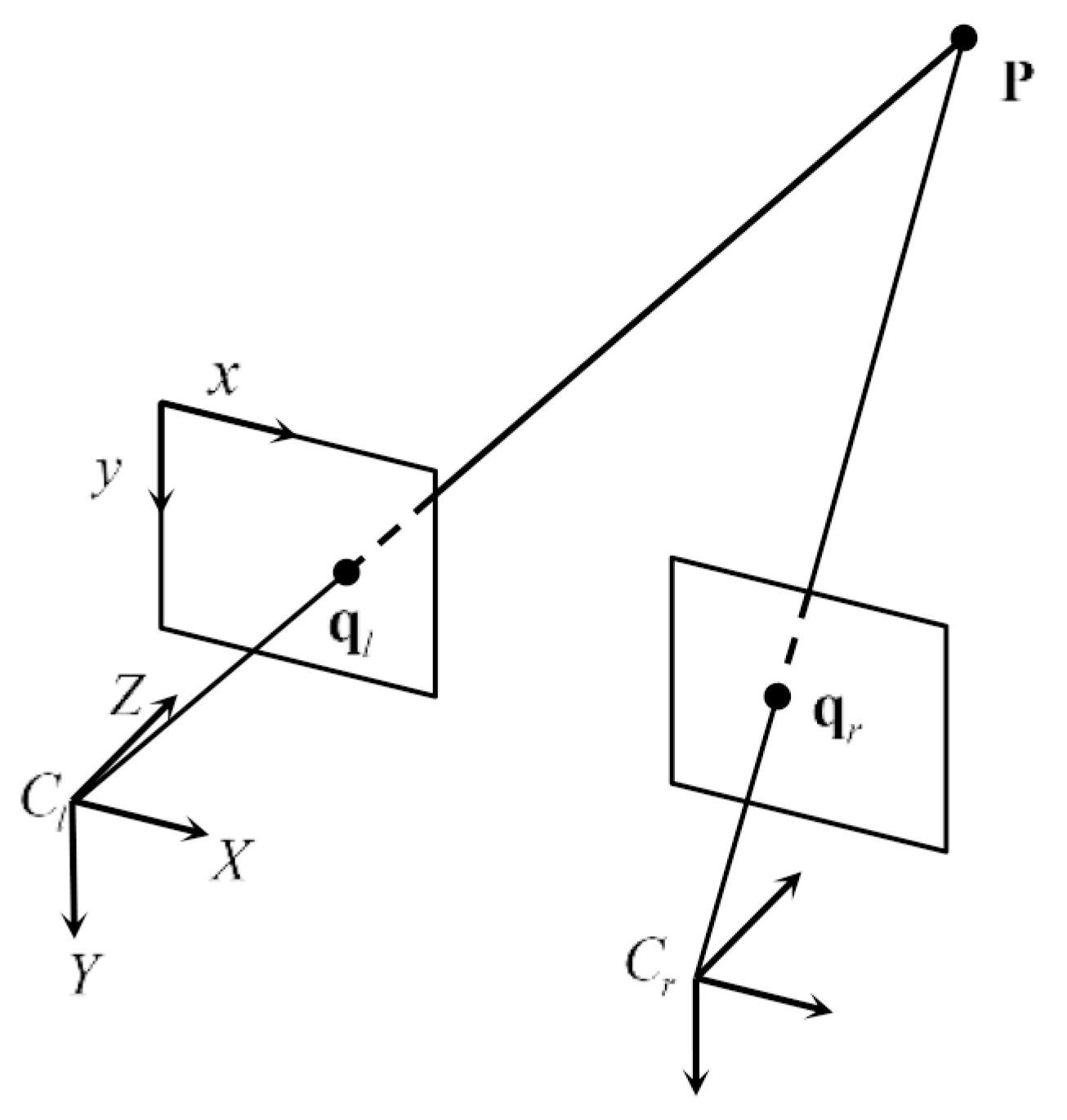
  • The three-dimensional (3-D) coordinates of the selected features are computed using triangulation.
  • The two-dimensional (2-D) features are tracked between the left images in frames k 1 and k using the AKT.
  • The SKM is performed by combining the standard KLT method [16] with the epipolar constraint. Then, the 3-D coordinates of the matched features are computed through triangulation.
  • The perspective-3-point (P3P) algorithm [18] is carried out in a random sample consensus (RANSAC) framework [19] to estimate the ego-motion from the 3-D-to-2-D correspondences.
  • The maximum likelihood estimator (MLE) [9,10] is applied to produce a robust ego-motion estimation.
  • The features inherited from Step 5 between the left images in frames k and k + 1 are continuously tracked. If the number of new tracked features is smaller than a predefined threshold N , repeat from Step 1. Otherwise, the features are inherited successfully and repeat from Step 6. The threshold is set to 30 to ensure both computational accuracy and efficiency. This process is called FI.
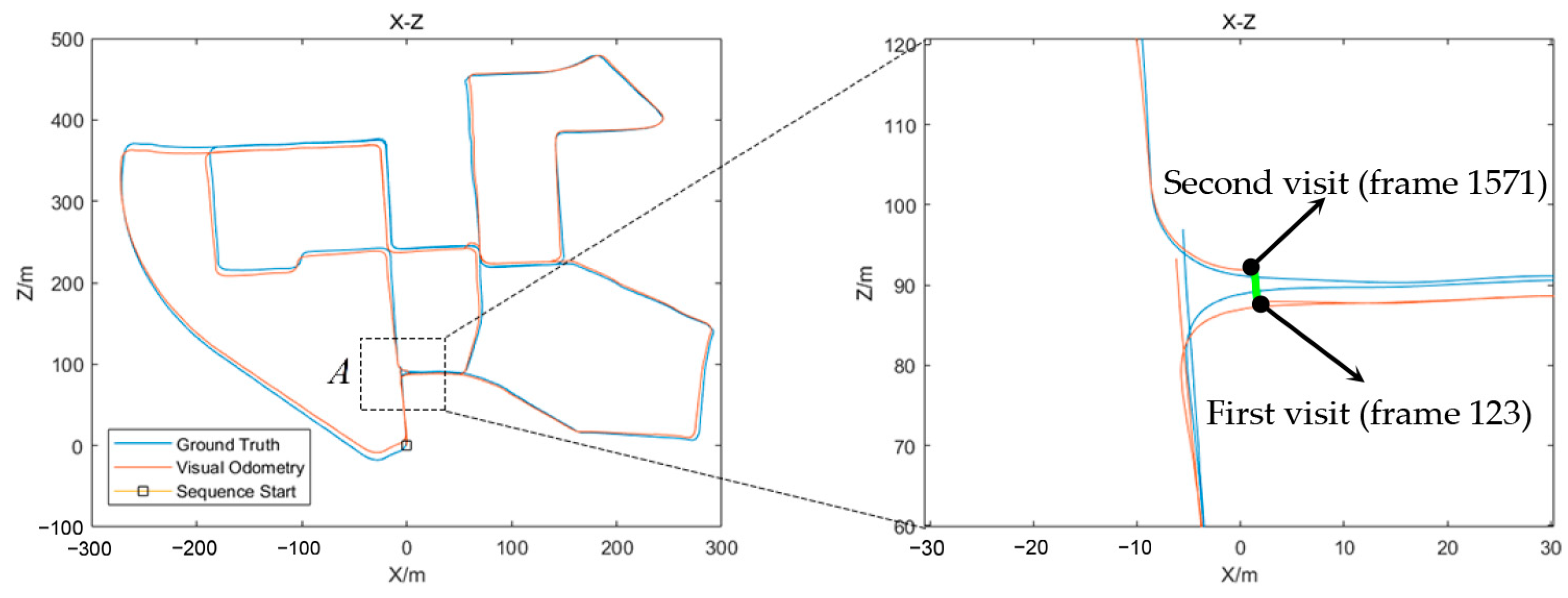
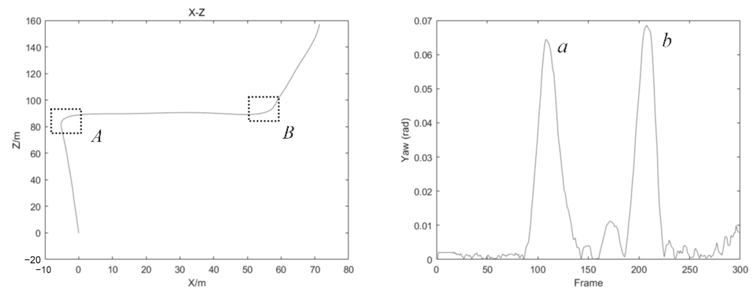
  • After Step 8, for a turning maneuver, the drift error is reduced via a VCM scheme. This scheme consists of a veer frame detection process and a veer frame matching process. If this is the first time through the corner or the intersection, a veer frame update will collect the current frame as the unique keyframe of this corner. If not, the motion between the current veer frame and the first veer frame of this corner is estimated and the drift error is corrected. This novel scheme will be described in Section 3.

3. Detailed Description of the Method

A detailed description of the steps required in the proposed SVO algorithm is provided in this section.

3.1. Feature Detection and Stereo Matching

Many feature detectors have appeared in SVO research, such as Harris [20], Shi-Tomasi [16], FAST [21], SIFT [22], and SURF [23]. These detectors have their own advantages and disadvantages. Note that both SIFT and SURF have been proven to be invariant to certain changes in perspective. The latter builds upon the former but uses box filters to border on the Gaussian, contributing to a faster computation [3]. Therefore, in this work, a SURF detector was employed to search for interest points in a first stereo frame and compute the SURF descriptors, where the stereo frame represents the left and right images taken at the same time.
After feature detection, stereo matching was performed on the basis of the similarity of the SURF descriptors, and an epipolar constraint was imposed. Specifically, with respect to the similarity measurement, the Euclidean distance between each descriptor in the left image and all the descriptors in the right image was calculated. Two feature points are considered to have correspondence only if their descriptors satisfy both conditions. First, the distance between two candidate points is less than a predefined threshold. In this case, for the normalized SURF descriptor, the distance threshold was set to 0.35. In addition, the distance from all other candidate points is larger than a certain threshold. This is implemented by checking whether the ratio between the closest and the second closest match is small enough. Typically, the ratio threshold for determining whether the correspondence is still live is set to 0.6. In addition, the epipolar constraint means that, for a well-calibrated stereo rig, the row coordinates of the correspondence feature points are approximately equal to the noise tolerance of one pixel.

3.2. Bucketing and Triangulation

Some studies have found that not all detected feature points are suitable for accurate tracking [16]. The work presented in [24] confirmed that feature selection can significantly reduce the number of iterations in the RANSAC scheme. This means that a subset of carefully selected features can not only prevent estimation bias, but also improve the real-time performance of SVO. Thus, it is generally required that the feature points should be uniformly distributed over the image plane, which can be implemented through bucketing technique [25]. In this case, each image is split into 50 × 50 pixel-sized blocks, i.e., buckets. In every bucket, only the strongest feature is kept, and the others are discarded.
Afterward, the 3-D coordinates of the selected features are calculated using intersecting rays projected through the stereo observation models, i.e., triangulation, as shown in Figure 2. In the absence of error, the rays of the same feature points in the stereo frame ( q l and q r ) intersect at point P in the 3-D spatial space. However, due to image noise, camera model uncertainty, and matching error, they do not always intersect. The shorter the distance between the two rays is, the more accurate the results that stereo matching can obtain. In the implementation, the feature correspondences which intersection distance is greater than 0.1 m is eliminated.

3.3. Adaptive KLT Tracker and Simplified KLT Matcher

In successive stereo frame k 1 , the AKT tracks the selected features to acquire their pixel coordinates in frame k . First, the optical flow corresponding to the feature point is solved in two consecutive left images I k 1 L and I k L . In the notation, the superscripts L and R index the “left” and “right” images, respectively, and the subscript k indexes the frame. The AKT minimizes Equation (1) using the Newton–Raphson method:
d = arg min d W k 1 [ I k L ( x + d ) I k 1 L ( x ) ] 2 ω ( x ) d x
where x = ( u , v ) is a feature point; d = ( Δ u , Δ v ) is the translation of the feature window’s center; W k 1 is the adaptive window; and ω ( x ) is a Gaussian weighting function. The correct optical flow computation of feature correspondences in frame k 1 generates the tracked features in the left image in frame k .
Because the standard KLT tracker assumes that the feature patch undergoes only translation motion, a fixed-window KLT is susceptible to scale distortion and affine transformation [26]. A small feature window is sensitive to noise, whereas a large feature window may not exhibit a clear or sharp response. In the following paragraphs, we indicate that it would be better to determine an adaptive window size for the KLT using the average disparity, the translation velocity, and the yaw angle. From the FRVO discussion in [6], a larger window size should be used for features with large motion, while a smaller window size should be used for a feature with small motion. FRVO uses disparity information to represent the motion experienced by the features, as shown in Figure 3; thus, an adaptive window size for the KLT is employed based on the disparity field. On a large scale, this must be true. However, for a specific feature, a large disparity does not mean that a large window is necessarily suitable. Especially for a feature near the road, a large motion is often accompanied by a large affine transformation. The experimental results demonstrate that a small window allows for a better tracking accuracy. Therefore, the proposed method does not pursue the optimal tracking accuracy for every feature, but for better overall performance. Instead of a dense disparity map, the average disparity is used as an indicator for the adaptive window size, which also reduces the computational complexity. On the other hand, disparity alone is not sufficient to characterize the motion of features. For example, when the translation velocity of the camera is slow, the local optical flow vector of each feature is small. Alternatively, for a turning maneuver, Figure 4 shows that the feature with a small disparity still has a larger optical flow vector. At this point, the tracking error tends to increase rapidly if the AKT relies on disparity information. Therefore, in addition to the average disparity in the current frame, the translation velocity of the camera and the yaw angle in the previous frame should be used to guide the adaptive window strategy. This makes it possible to use a small window for the AKT even when the disparity of features is large. Based on the discussion above, a joint adaptive function (JAF) is built as follows:
W k = c d ( d k d 0 ) + c v ( v k 1 v 0 ) + c α ( α k 1 α 0 ) + b
where W k is the adaptive window size for the AKT in frame k ; d k , v k 1 , and α k 1 are the average disparity in frame k , the translation velocity of the camera, and the yaw angle in frame k 1 , respectively; d 0 , v 0 , and α 0 are the constant offsets; c d , d v , and c α are the disparity, the velocity, and the yaw angle weighting coefficients, respectively; and b is the base window size. The parameters ( d 0 , v 0 , α 0 , c d , c v , c α , and b ) are empirically set to be (20 pixels, 1.0 m/frame, 0.02 rad, 1, 10, −100, and 17), respectively. Meanwhile, the window size B k has the lower and upper bounds of 5 and 49, respectively. Note that the adaptive window size is determined using the first-order approximation. An interesting future direction would be to explore a nonlinear model for the JAF and obtain the above parameters in a learning framework.
After the tracking step, for a rectified stereo frame, stereo matching can be conducted strictly along the epipolar line. Combining the KLT method with the epipolar constraint, the component of the displacement d in the row direction is approximately equal to zero. This means that the SKM looks for feature correspondences only in the column direction. Thus, the SKM between the left and right images I k L and I k R in frame k can be represented as follows:
d = arg min d W [ I k L ( u , v + d ) I k R ( u , v ) ] 2 ω ( u , v ) d u d v
where d is the disparity. The resulting set is also projected to 3-D space via triangulation.
Afterward, when estimating the camera pose in frame k + 1 , the input to the new AKT is no longer the output of the SURF detector but the output of the SKM, i.e., the FI. This means that the new SURF feature detection will be taken into account only if the number of new tracked features is lower than a predefined threshold. Due to the FI, the AKT, and the SKM, the approach presented here can avoid both feature detection and feature-based stereo matching as much as possible. Consequently, the computational time is considerably reduced.

3.4. RANSAC-P3P and Maximum Likelihood Estimator

Almost all robust SVO methods employ the RANSAC scheme for motion estimation when there are noise and outliers with the feature detector, matcher, and tracker. In this paper, ego-motion is estimated through the RANSAC-P3P reported by Fischler and Bolles in [19], where a set of closed-form hypotheses on the minimum number of data needed to obtain a solution is solved, and the hypothesis that shows the highest consensus with the other data is selected as an initial solution. Then, the MLE [9,10] is applied to produce a final, corrected ego-motion estimation between the two consecutive frames.

3.5. Veer Chain Matching

As there is scale distortion and affine transformation due to rotation, the KLT tracking error tends to increase rapidly for a turning maneuver. To limit the drift error, an easy and effective VCM scheme is proposed, which draws inspiration from the loop closing of the ORB-SLAM2 [11]. However, this VCM scheme employs a veer frame detector and matcher, avoiding the time-consuming loop closure detection and achieving high accuracy, especially for an urban environment with more corner loops.
Generally, in order to form a closed loop in a trajectory, one of the following conditions should be met: (1) there is a large veer in the trajectory, or (2) there is a long-term cumulative turn in the same yaw direction. Inspired by this, a vehicle would only be possible to revisit a site through a corner or after a turning maneuver. Figure 5 shows the path reconstructed from our SVO method compared to the ground truth data on sequence 00 of the KITTI odometry dataset. The vehicle leaves corner A on frames 123 and 1271. The VCM scheme can correct the drift error on the next visit.
The basic idea of VCM is to detect veer frames using the yaw angle of the current frame relative to the previous frame. As shown in Figure 6, when there is a large angle of veer in the trajectory, there must be a large peak in the yaw angle diagram. Thus, if the yaw angle is larger than some threshold, this demonstrates that a turning maneuver is underway, and the corresponding stereo frame is regarded as a veer frame. Once a key veer frame is obtained, the VCM scheme is triggered to reduce the drift error. The key to the above approach is to determine the yaw angle threshold. A large threshold angle is likely to lead to missing detection, while a small threshold angle reduces the time efficiency of the VCM. It can be observed that the size of the yaw angle peak is proportional to the velocity and the veer angle. Therefore, in this case, 50% of the yaw angle peak is taken as the threshold when passing through a right-angle corner at a slower speed, which is 0.03 rad. If this is the first time through the corner or the intersection, the last veer frame will be regarded as the unique keyframe of the corner. These keyframes and their locations are collected into a set V . The reason for this is that the drift error can always be corrected when the vehicle leaves the corner. When a key veer frame is detected, this information is used to reduce the drift in the vehicle path. If the SVO revisits these locations, veer frame matching is performed between the current veer frame and all the keyframes in the set V . Here, the ZNCC method [25] is used. If the number of matched features is larger than some threshold, the motion estimator between the corresponding veer frame pair can correct the drift error. In the implementation, the threshold is set to 45. Otherwise, a veer frame update will regard the current veer frame as the unique keyframe of this corner. Although the veer frame matcher is not triggered the next time the vehicle goes straight through the corner, due to the introduction of the veer frame detector, the match still has a very high precision and recall rate, especially in an urban environment with more corner loops. Moreover, the VCM scheme is obviously much faster than loop closure detection.

4. Experimental Results

In this section, the proposed approach was evaluated using the publicly available KITTI odometry dataset, which is composed of captured videos along with an accurate ground truth. The rectified stereo images with a size of 1241×376 are recorded at a frequency of 10 Hz. In the following experiments, for each training sequence of the KITTI dataset except sequence 01, thirty trials were conducted, and the average translational error e t , the average rotational error e r relative to the ground truth, and the runtime per frame were employed as the performance metrics. For sequence 01, a highway scenario with largely distant image areas driving at high speed does not apply to the KLT tracker. Therefore, the performance of this method was evaluated on the other 10 training sequences, which included urban and rural scenarios. All of the experiments were performed using a PC with an Intel Core i5 9500 3.0 GHz processor and a 16 GB RAM using a single thread. In order to prove that the improved algorithm could greatly reduce the computational complexity without notably compromising the localization accuracy, MATLAB was used to conduct the simulation experiments on the prototype of the algorithm (there is no code optimization). Even so, the system could run at 15 Hz.
Considering the trajectory, Figure 7 shows the path reconstructed from our SVO compared to the ground truth data on several sequences of the KITTI dataset. They have the same shapes. Table 1 shows the average translation error and rotation error on the 10 training sequences. Although sequences 01 and 05 with corner loops have 3723 m and 2204 m of traveling, respectively, the proposed SVO with the JAF and the VCM can obtain an average translation error of 0.9496% and 0.5957%, and a rotation error of 0.0008 deg/m and 0.0016 deg/m, respectively. Meanwhile, sequences 03 and 07 without corner loops have a shorter path (561 m and 695 m, respectively); hence, the proposed approach also has a high localization accuracy, with an average translation error of 1.0257% and 0.6460%, and a rotation error of 0.0005 deg/m and 0.0055 deg/m, respectively. The results in Figure 7e,f have been obtained without the VCM scheme for a long path, which leads to a slightly worse error. However, there is no difference in runtime. This means that the proposed VCM can greatly improve the localization accuracy while not sacrificing time performance. Furthermore, the proposed method was compared to a version that determines the AKT window size using only disparity information, as shown in Table 1. One can observe that both the JAF and the VCM help to significantly improve the localization accuracy. On average, the translation and rotation errors on the 10 train sequences are (1.1361%, 0.0021 deg/m) and (1.6254%, 0.0023 deg/m), respectively. Therefore, the AKT using the JAF performs 30% better than the AKT using only disparity information, while the JAF does not require extra runtime.
To further evaluate the improvement in time performance, Table 1 shows the average runtime per frame of the 10 training sequences. Thanks to the FI, the AKT, and the SKM, the proposed SVO thread runs at 0.0658 s per frame with a standard deviation of 0.0161 s. This means that the proposed SVO can run in real time at 15 Hz on the KITTI odometry dataset. The deviation is mainly caused by the differences in the number of scenario features and corner loops. Because the data in Table 1 are normally distributed, a Mann–Whitney U nonparametric test was used to further analyze the differences in runtime, e t and e r , between the two versions. The test was performed with the help of an SPSS v24 computer program using a 95% confidence level. The hypotheses of this test are as follows:
  • H r u n t i m e a , H e t a , and H e r a represent no significant difference in runtime, e t and e r , between the two versions, respectively.
  • H r u n t i m e b , H e t b , and H e r b represent a significant difference in runtime, e t and e r , between the two versions, respectively.
As shown in Table 2, the Mann–Whitney U test results demonstrate that H r u n t i m e a , H e t b and H e r a are acceptable ( P r u n t i m e = 0.7624 > 0.05 , P e t = 0.0059 < 0.05 , and P e r = 0.6224 > 0.05 ), which means that the JAF can significantly improve the robustness and accuracy without increasing the runtime. This beneficial behavior is mainly because the translation velocity and the yaw angle in the JAF have already been computed in the previous frame.
Moreover, on sequences 05 (with corner loops) and 07 (without corner loops), the comparison of the average processing times at every stage between our method and a version without the FI and VCM that performs SURF detection, feature-based stereo matching, AKT, and SKM at each frame is shown in Table 3. It can observe that the proposed method helps reduce runtime significantly, and the times spent on feature detection, stereo matching, and motion estimation are reduced by approximately 3 times. In conclusion, the total processing times are reduced by more than 40%.
For completeness, several real-time systems were compared in the subsequent experiments in order to evaluate the performance of the proposed algorithm. They included the SOFT2 [4], the most accurate SVO; the ORB-SLAM2 [11], a complete SLAM system that has four parallel threads; the FRVO [7], the fastest single-thread SVO on the KITTI leaderboard until now; the SVO-FPGA [12], a multiple master-slave FPGA architecture for a SIFT-based SVO; and the VOLDOR [13], a dense indirect VO based on GPU. Table 4 shows the runtime, the average translation error, and the average rotation error of the proposed method compared to other methods, using always the results published by the original authors. Although the proposed approach is slightly less accurate than SOFT2, the ORB-SLAM2, and the FRVO, all can provide very accurate estimations. In particular, the proposed method outperforms in terms of runtime. The proposed approach is 34% better than the SOFT2 and is similar to the ORB-SLAM2. However, the ORB-SLAM2 splits SLAM into four parallel threads and is more costly, while the proposed SVO is a single-thread system. For the FRVO, the runtime of 0.03 s does not include the time for the dense disparity map computation, which is usually a time-consuming process and requires at least an extra 0.03 s. The proposed approach jointly determines the suitable KLT window size using the average disparity, the translation velocity, and the yaw angle; thus, no time-consuming computation of a dense disparity map is needed. Although the accuracy of the proposed method is slightly inferior in terms of relative translation errors, with an error of 1.14% against the 0.98% of the FRVO, its main advantage is the real-time performance even on a lower-speed processor. Moreover, Table 4 compares the performance of our method and two state-of-the-art SVO methods that are implemented in parallel with the FPGA and the GPU, namely the SVO-FPGA and the VOLDOR. It can be observed that the proposed method can strike a good trade-off between efficiency and accuracy and can greatly improve the computational efficiency, while not needing to sacrifice accuracy. Furthermore, the results confirm that the proposed algorithm can run much faster in C/C++. This distinctly demonstrates that the three strategies, i.e., the FI, the AKT, and the SKM, in the proposed method contribute to a significant improvement in the SVO real-time performance.

5. Conclusions

This paper presents a novel algorithm for stereo visual odometry that avoids time-consuming feature detection and matching processes as much as possible based on feature inheritance, an adaptive KLT tracker, and a simplified KLT matcher, which can greatly reduce computational complexity without notably compromising the localization accuracy. Based on the average disparity, the translation velocity, and the yaw angle, the proposed method can jointly determine a suitable window size for the KLT tracker, which effectively mitigates the effect of scale distortion and affine transformation. Furthermore, an effective veer chain matching scheme can be employed to limit the drift error. In the experiments, the method presented here was tested on the KITTI odometry dataset and compared with other methods. According to the experimental results, although the translation error of the proposed SVO is slightly less accurate than some state-of-the-art methods, with an error of 1.14% against an error of 0.71% for the SOFT2, an error of 73% for the ORB-SLAM2, and an error of 0.98% for the FRVO, the proposed method can strike a good trade-off between efficiency and accuracy. Efficiency is achieved in that the system is able to run at 15 Hz on a single-thread CPU @ 3.0 GHz, outperforming even the parallel or multi-threaded approaches in the balance between high accuracy and low computational complexity.

Author Contributions

Conceptualization, G.G. and Z.D.; methodology, G.G.; software, G.G.; validation, G.G., Z.D. and Y.D.; formal analysis, G.G.; investigation, G.G.; resources, G.G. and Y.D.; data curation, G.G. and Y.D.; writing—original draft preparation, G.G.; writing—review and editing, G.G.; visualization, G.G.; supervision, Z.D. All authors have read and agreed to the published version of the manuscript.

Funding

This research received no external funding.

Institutional Review Board Statement

Not applicable.

Informed Consent Statement

Not applicable.

Data Availability Statement

Not applicable.

Conflicts of Interest

The authors declare no conflict of interest.

References

  1. Chen, Y.; Mei, Y.; Wan, S. Visual Odometry for Self-Driving with Multihypothesis and Network Prediction. Math. Probl. Eng. 2021, 2021, 1930881. [Google Scholar] [CrossRef]
  2. He, M.; Zhu, C.; Huang, Q.; Ren, B.; Liu, J. A review of monocular visual odometry. Vis. Comput. 2020, 36, 1053–1065. [Google Scholar] [CrossRef]
  3. Fraundorfer, F.; Scaramuzza, D. Visual odometry: Part II: Matching, robustness, optimization, and applications. IEEE Robot. Autom. Mag. 2012, 19, 78–90. [Google Scholar] [CrossRef] [Green Version]
  4. Cvišić, I.; Marković, I.; Petrović, I. Recalibrating the KITTI Dataset Camera Setup for Improved Odometry Accuracy. In Proceedings of the 2021 European Conference on Mobile Robots (ECMR), Bonn, Germany, 31 August–3 September 2021; pp. 1–6. [Google Scholar]
  5. Fraundorfer, F.; Scaramuzza, D. Visual odometry: Part I: The first 30 years and fundamentals. IEEE Robot. Autom. Mag. 2011, 18, 80–92. [Google Scholar]
  6. Wu, M.; Lam, S.K.; Srikanthan, T. A Framework for Fast and Robust Visual Odometry. IEEE T. Intell. Transp. 2017, 18, 3433–3448. [Google Scholar] [CrossRef]
  7. Geiger, A.; Ziegler, J.; Stiller, C. Stereoscan: Dense 3d reconstruction in real-time. In Proceedings of the IEEE Intelligent Vehicles Symposium (IV), Baden-Baden, Germany, 5–9 June 2011; pp. 963–968. [Google Scholar]
  8. Wan, W.; Liu, Z.; Di, K.; Wang, B.; Zhou, J. A Cross-Site Visual Localization Method for Yutu Rover. In Proceedings of the International Archives of the Photogrammetry, Remote Sensing and Spatial Information Sciences (ISPRS), Suzhou, China, 14–16 May 2014; Volume XL-4. [Google Scholar]
  9. Cheng, Y.; Maimone, M.; Matthies, L. Visual odometry on the Mars exploration rovers. In Proceedings of the 2005 IEEE International Conference on Systems, Man and Cybernetics, Waikoloa, HI, USA, 12 October 2005; pp. 903–910. [Google Scholar]
  10. Maimone, M.; Cheng, Y.; Matthies, L. Two years of visual odometry on the mars exploration rovers. J. Field Robot. 2007, 24, 169–186. [Google Scholar] [CrossRef] [Green Version]
  11. Mur-Artal, R.; Tardós, J.D. ORB-SLAM2: An Open-Source SLAM System for Monocular, Stereo, and RGB-D Cameras. IEEE Trans. Robot. 2017, 33, 1255–1262. [Google Scholar] [CrossRef] [Green Version]
  12. Chien, C.H.; Hsu, C.C.J.; Chien, C.J. Multiple Master-Slave FPGA Architecture of a Stereo Visual Odometry. IEEE Access 2021, 9, 103266–103278. [Google Scholar] [CrossRef]
  13. Min, Z.; Yang, Y.; Dunn, E. VOLDOR: Visual Odometry From Log-Logistic Dense Optical Flow Residuals. In Proceedings of the 2020 IEEE/CVF Conference on Computer Vision and Pattern Recognition (CVPR), Seattle, WA, USA, 13–19 June 2020; pp. 4898–4909. [Google Scholar]
  14. Ferrera, M.; Eudes, A.; Moras, J.; Sanfourche, M.; Le Besnerais, G. OV2SLAM: A Fully Online and Versatile Visual SLAM for Real-Time Applications. IEEE Robot. Autom. Lett. 2021, 6, 1399–1406. [Google Scholar] [CrossRef]
  15. Moreno, F.A.; Blanco, J.L.; González, J. An efficient closed-form solution to probabilistic 6D visual odometry for a stereo camera. In Proceedings of the International Conference on Advanced Concepts for Intelligent Vision Systems (ACIVS), Delft, The Netherlands, 28–31 August 2007; Springer: Berlin/Heidelberg, Germany, 2007; Volume 4678, pp. 932–942. [Google Scholar]
  16. Shi, J. Good features to track. In Proceedings of the IEEE Conference on Computer Vision and Pattern Recognition (CVPR), Seattle, WA, USA, 21–23 June 1994; pp. 593–600. [Google Scholar]
  17. Geiger, A.; Lenz, P.; Stiller, C.; Urtasun, R. Vision meets robotics: The kitti dataset. Ind. Robot. 2013, 32, 1231–1237. [Google Scholar] [CrossRef] [Green Version]
  18. Alismail, H.; Browning, B.; Dias, M.B. Evaluating pose estimation methods for stereo visual odometry on robots. In Proceedings of the 11th International Conference on Intelligent Autonomous Systems (IAS-11), Ottawa, ON, Canada, 30 August–1 September 2010; pp. 101–110. [Google Scholar]
  19. Fischler, M.A.; Bolles, R.C. Random sample consensus: A paradigm for model fitting with applications to image analysis and automated cartography. Commun. ACM 1981, 24, 381–395. [Google Scholar] [CrossRef]
  20. Harris, C.G.; Pike, J. 3D positional integration from image sequences. Image Vision Comput. 1988, 6, 87–90. [Google Scholar] [CrossRef] [Green Version]
  21. Rosten, E.; Drummond, T. Machine learning for high-speed corner detection. In European Conference on Computer Vision (ECCV); Springer: Berlin/Heidelberg, Germany, 2006; Volume 3951, pp. 430–443. [Google Scholar]
  22. Lowe, D.G. Distinctive image features from scale-invariant keypoints. Int. J. Comput. Vision 2004, 60, 91–110. [Google Scholar] [CrossRef]
  23. Bay, H.; Tuytelaars, T.; Van Gool, L. SURF: Speeded Up Robust Features. In European Conference on Computer Vision (ECCV); Springer: Berlin/Heidelberg, Germany, 2006; Volume 3951, pp. 404–417. [Google Scholar]
  24. Cvišić, I.; Petrović, I. Stereo odometry based on careful feature selection and tracking. In Proceedings of the 2015 European Conference on Mobile Robots (ECMR), Lincoln, UK, 2–4 September 2015; pp. 1–6. [Google Scholar]
  25. Silva, H.; Bernardino, A.; Silva, E. Probabilistic egomotion for stereo visual odometry. J. Intell. Robot. Syst. 2015, 77, 265–280. [Google Scholar] [CrossRef]
  26. Ramakrishnan, N.; Srikanthan, T.; Lam, S.K.; Tulsulkar, G.R. Adaptive Window Strategy for High-Speed and Robust KLT Feature Tracker. In Image and Video Technology; PSIVT 2015; Lecture Notes in Computer Science; Bräunl, T., McCane, B., Rivera, M., Yu, X., Eds.; Springer: Cham, Switzerland, 2015; Volume 9431, pp. 355–367. [Google Scholar]
Figure 1. Flowchart of the proposed approach.
Applsci 12 12124 g001
Figure 2. Stereo observation model.
Applsci 12 12124 g002
Figure 3. (a): Feature point tracking results in frame 0 on sequence 00 of the KITTI odometry dataset. The yellow arrow indicates the optical flow vector of the feature point. (b): Relationship between the disparity and the optical flow when the translation velocity is fast and the yaw angle is small; features with a large disparity are prone to large motion and features with a small disparity are prone to small motion. Each blue dot corresponds to a feature point in (a).
Applsci 12 12124 g003
Figure 4. (a): Feature point tracking results in frame 99 on sequence 00 of the KITTI odometry dataset. The yellow arrow indicates the optical flow vector of the feature point. (b): Relationship between the disparity and the optical flow for a turning maneuver; regardless of the size of the disparity, all features have large motion. Each blue dot corresponds to a feature point in (a).
Applsci 12 12124 g004aApplsci 12 12124 g004b
Figure 5. VCM on sequence 00. The green line indicates the drift error correction of frame 1571 where the vehicle revisits corner A .
Applsci 12 12124 g005
Figure 6. The veers A and B in the trajectory (left) correspond to the peaks a and b in the yaw angle diagram (right), respectively.
Applsci 12 12124 g006
Figure 7. Reconstructed path for (a) sequence 00; (b) sequence 03; (c) sequence 05; (d) sequence 07; (e) sequence 08; and (f) sequence 10.
Applsci 12 12124 g007
Table 1. Comparison of the proposed method to a version that determines the AKT window size using only disparity information on the KITTI dataset. (deg/m stands for degrees per meter).
SVO + FI + AKT + SKM + VCM + JAFSVO + FI AKT + SKM + VCM + Disparity
SequenceRuntime (s) e t (%) e r   ( deg / m ) Runtime (s) e t   ( % ) e r   ( deg / m )
000.07290.94960.00080.07031.38440.0012
020.07341.20110.00130.06501.20420.0009
030.03581.02570.00050.03971.70080.0010
040.05460.53610.00010.06001.66630.0001
050.05970.59570.00160.05991.02910.0015
060.09781.12530.00060.09221.74300.0011
070.05850.64600.00550.06120.87420.0068
080.06352.15400.00040.06742.90200.0011
090.06701.35690.00150.07111.97720.0015
100.07441.77080.00910.07521.77310.0075
avg0.06581.13610.00210.06621.62540.0023
Table 2. Hypothesis Testing.
Test DataRuntime e t e r
Mann–Whitney U46.000025.000043.5000
Wilcoxon W101.000080.000099.5000
Z−0.3024−1.8898−0.4925
Asymp. Sig. (2-tailed)0.76240.00590.6224
Table 3. Processing time in milliseconds of each stage for sequences 05 and 07 in the KITTI dataset.
Our MethodSVO
(Without FI and VCM)
StageSeq. 05Seq. 07Seq. 05Seq. 07
Feature detection20.434019.812861.050262.4008
Stereo matching1.85561.85495.60626.3031
AKT4.15323.60802.68902.8666
SKM2.50292.50252.51952.5339
VCM18.145317.9953\\
Motion estimation4.11765.082022.328816.9736
Total59.704459.4217103.0680100.0306
Table 4. Comparison of state-of-the-art methods on the KITTI dataset.
MethodRuntime (s)et (%)er (deg/m)Environment
SOFT20.10.710.00242.5 GHz (C/C++)
ORB-SLAM20.060.730.00223.6 GHz (C/C++)
FRVO0.03 (excluding the time for disparity map computation)0.980.00563.5 GHz (C/C++)
SVO-FPGA0.03012.7\4.2 GHz +FPGA
VOLDOR0.11.320.0042GPU
Proposed0.06581.140.00213.0 GHz (MATLAB)
Publisher’s Note: MDPI stays neutral with regard to jurisdictional claims in published maps and institutional affiliations.

