Abstract
In this paper, the dynamic balance of a rigid variable speed rotor is tested and analyzed. The vibration acceleration is measured by vibration analyzer instrumentations. The rotor adjustment parameters of counterweight, pitch, and trailing-edge flap are considered. The amplitude and phase of the 1 Ω vibration acceleration are analyzed through an all-phase fast Fourier transform. The experiments are conducted using two rigid rotors with the same geometry. The accelerations of the fuselage in the , and directions are measured. Through a waterfall diagram of the auto-power spectrum, it is found that the imbalance of counterweight, pitch, and trailing-edge flap causes an obvious increase in 1 Ω and 2 Ω acceleration. The hub counterweight mainly causes the lateral and longitudinal vibration in the disc plane, and the aerodynamic factors such as pitch and trailing-edge flap mainly affect the vertical vibration. In order to achieve dynamic balance for variable speed rotors, the counterweight adjustment should be given the highest priority for the vibration in the disc plane, and the pitch and trailing-edge flap adjustment should be given the highest priority for the vertical vibration. The results obtained from this experiment may be helpful toward reasonable designs of variable speed rotor helicopters.
1. Introduction
Helicopters have been widely used in military and civil fields, but the vibration level in modern helicopters is more than twice that in fixed-wing aircraft. Up to 20% of helicopter accidents are caused by vibration, and 35% of these result from rotor vibration [1,2]. Therefore, reducing the helicopter vibration level can improve the safety of helicopters.
The rotor is the main vibration source in the helicopter. Rotor vibration is mainly caused by mass and aerodynamic imbalances between the blades during the machining, manufacture, use, and maintenance of the blades. These imbalances generate periodic alternating forces or moments on the rotor and transmit it to the fuselage, resulting in an increase in the vibration level of the helicopter, especially the low-frequency vibration within 20 Hz, to which the human body is more sensitive. As a result, the helicopter’s comfort level and combat endurance capability are reduced. At the same time, the vibration also affects the use efficiency and life of equipment and weapons [3,4]. Therefore, during the use and maintenance of helicopters, it is necessary to adjust the rotor parameters to ensure rotor dynamic balance and minimize the vibration caused by the imbalance of the rotor [5].
There is some research that focuses on helicopter vibration. Rafiee et al. [6] presented a comprehensive review of scholarly articles about rotating beams that were published in the past decades. Ece et al. [7] investigated vibration of an isotropic beam that has a variable cross-section. Ma et al. [8] developed a new dynamic model of rotor-blade systems considering the lateral and torsional deformations of the shaft; the gyroscopic effects of the rotor, which of shaft and disk; and the centrifugal stiffening, spin softening and Coriolis force of the blades. Wang et al. [9] studied rotor unbalance identification.
Ventres and Hayden [10] established a mapping relationship between blade parameters and vibration in the frequency domain and applied it to control high-order vibration. At the same time, the optimal parameter is searched by an optimization algorithm to reduce the fundamental vibration. Ganguli [11,12,13,14,15,16,17,18] published several papers that report on the effect of rotor diagnosis in different ways. His research involves many different types of rotor faults, such as beam crack, composite material delamination, lag damper failure, and pitch-rod damage, including rotor mass imbalance caused by weight loss and aerodynamic imbalance caused by blade pitch or blade trailing-edge flap. The research objectives include various parameters such as natural frequencies of the blade, six-force-factor of the hub, tip displacement, etc. Chopra et al. [19,20] used the finite element method to model the rotor system of an S-60 helicopter, and used the relationship between rotor adjustment parameters and fuselage vibration for digital simulation. At the same time, combined with flight test data, a neural network relationship model of the rotor system was established. Yang et al. [21,22] established a rotor fuselage model. Based on the assumption that each blade in the rotor model is independent of each other, they analyzed the effect of rotor adjustment parameters on the vibration of the fuselage with a frequency of 1 Ω (Ω is the rotor speed). With the increase in flight speed, the vibration increases continuously. Based on the research of rotor imbalance test, Wang et al. [23,24] proposed an optimization adjustment of rotor dynamic balance to reduce the helicopter vibration level and improve the adjustment efficiency of rotor dynamic balance. Samuel et al. [25] reviewed and summarized vibration-based techniques for helicopter transmission diagnostics. Wang et al. [26] presented an efficient and comprehensive vibration analysis method for a helicopter rotor-fuselage coupling system. Lee et al. [27] alleviated numerically both the rotor and airframe vibrations of a lift-offset compound helicopter using two different active vibration control techniques. Ji et al. [28] studied to reduce helicopter 1/rev vibration using an extendable trailing-edge plate. Zhou et al. [29] investigated the actively controlled flap (ACF) to reduce the rotor dynamic load by using a three-blade helicopter rotor. Park et al. [30] investigated reducing the hub vibratory loads of a lift-offset rotor using IBC (individual blade pitch control) in high-speed forward flight.
As an ideal green vehicle, electric helicopters use electric power as the power source for the propulsion system, which has the advantages of energy conservation, environmental protection, low vibration, and high efficiency, and is expected to be widely used in future general aviation [31,32,33,34,35]. In terms of electric helicopters, Johnson of the United States has established a variety of power system models, including electric power [36], by studying the electric refitting of R22 helicopters [37] and by systematically analyzing the characteristics of lithium polymer batteries, hydrogen fuel cells, and motors. The flight performance of an electric R22 helicopter is calculated and analyzed. Xie et al. [38] developed a global optimum envelope method for balancing performance improvements in hover and various freestream velocities. Guan et al. [39] studied the mechanism of the variable-speed rotor affecting the rotor aerodynamic performance by means of dimensionless parameter analysis, and reveals the various effect mechanisms under the different flight speeds and takeoff weights. Xu et al. [40] studied the aerodynamic performance of a variable-speed coaxial helicopter. The results show that the variable-speed coaxial helicopter has low required power when it is less than the forward flight speed corresponding to the hovering rotor speed. The variable-speed rotor has proven to be a promising means to improve helicopter performance. Zhao et al. [41,42] proposed a novel transient balancing technology for the identification and diagnosis of transient dynamic balancing of aero-engine rotor systems. Most research on rotor dynamic balance are aimed at traditional helicopters that work at a fixed speed. There have been few investigations into the dynamic balance of variable-speed rotor helicopters.
The purpose of this paper is to investigate the influence of rotor adjustment parameters on the dynamic balance of rigid variable-speed rotors at different speeds. The experiment was conducted in the helicopter of the Key Laboratory of Ministry of Education at Beihang University. The experiment was carried out using two scale-model rigid rotors with the same geometry. Rotor adjustment parameters involve counterweight, pitch, and trailing-edge flap. The experimental data are measured and analyzed, respectively, through vibration analyzer installations and an all-phase fast Fourier transform. Through a waterfall diagram of the auto-power spectrum and amplitude and phase diagram of 1 Ω vibration acceleration, the influence of adjustment parameters on fuselage vibration at different speeds is analyzed.
2. Experiment Setup
2.1. Rotor System
The experiment was conducted on a model-scale rigid-rotor system having a two-bladed rotor, as shown in Figure 1, in the helicopter of the Key Laboratory of Ministry of Education in Beihang University. The model-scale rigid-rotor system tested in this investigation consists of two 0.5 m diameter bladed rotors. Each blade is untwisted and has a rectangular planform with a uniform chord length of , with a blade root cutout of (about rotor radius). Additionally, the rotor blades have NACA0012 symmetrical airfoil sections and are of all-aluminum construction. The detailed rotor properties are shown in Table 1. The rotor drive mechanism consists of a hub mounted on a rotating drive shaft. The rotors are powered by an electric motor through a belt transmission that has a 4:1 transmission ratio, which can be seen in Figure 2. The rotor is equipped with a Hall-effect speed sensor to indicate the rotor speed. During the tests, the rotor speed was set to . The rotor blade hubs are hingeless and rigid, and the collective pitch angles are set at . The collective pitch angles are all from the prior experimental databases for actual rigid-rotor helicopter flight in the laboratory [43,44].
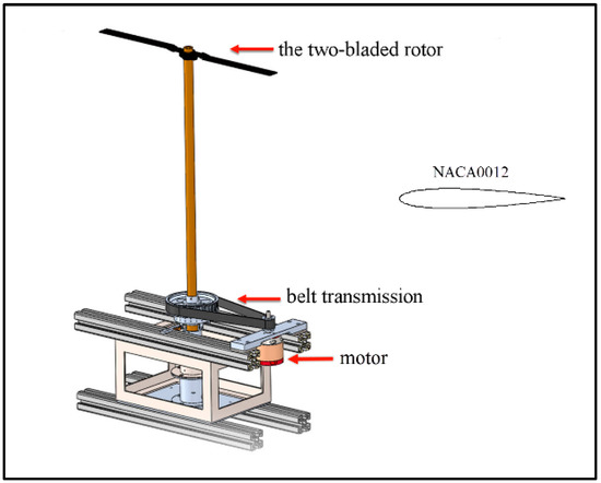
Figure 1.
View of the small-scale compound rigid-rotor system and the symmetrical airfoil section.

Table 1.
Properties of the test rotor in this experiment.
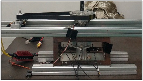
Figure 2.
Local view of the belt transmission, Hall-effect speed sensor, and acceleration sensor.
2.2. Vibration Analyzer Instrumentation
Figure 3 shows the vibration analyzer system and the model-scale rotor test setup. The vibration measurement system consists of data acquisition analysis (DAS) instrument AVANT MI-7016, single-axial acceleration transducer EA-YD-185, three-axial acceleration transducer EA-YD-3193-5, and a computer. DAS is a highly accurate signal analysis instrument based on DSP, which is mainly composed of an analyzer and the PC application software. The analyzer is in charge of data acquisition and real-time analysis. All real-time analysis is performed by the DSP processor, including signal acquisition, sampling, filtering, instant analysis, waveform source output, etc. DAS has 16 input channels. Three single-axial acceleration transducers are connected to 1/2/3 input channels to measure the x, y, and z acceleration on the fuselage.
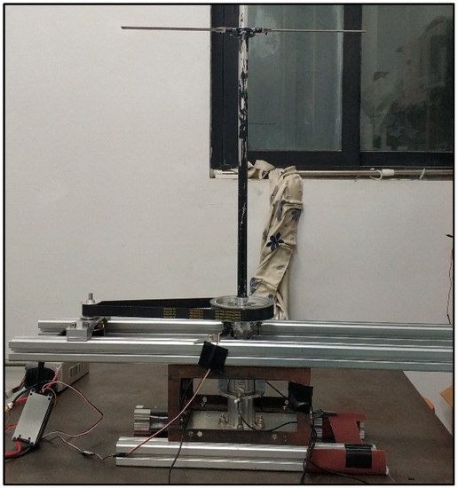
Figure 3.
Rotor test stand.
2.3. Vibration Measurement Working Process
Figure 4 shows the working process of the vibration analyzer system. The sleeve supporting the rotor shaft is used as the installation point for the acceleration transducer. Three single-axis acceleration transducers are installed in the positive direction of the X, Y, and Z axes. The three acceleration transducers are uniformly installed on the outer edge of the shaft sleeve. The acceleration transducers are connected to the dynamic signal analyzer through a customized cable. The dynamic signal analyzer is connected to the computer via a USB communication line. The Hall-effect speed sensor is installed on the fuselage and connected to the R7008SB receiver through a specific data line. The motor is mounted on the fuselage and connected to the ESC through a special data line. The ESC is powered by the battery to transmit data to the R7008SB receiver. The pitch is measured by the electronic pitch gauge and fixed by the hub bolts. The throttle lever of FUTABA T14SG is adjusted to control the motor speed. FUTABA T14SG transmits the signal to the R7008SB receiver, and the R7008SB receiver transmits to the ESC. The ESC controls and adjusts the motor speed, and the motor drives the rotor to rotate.
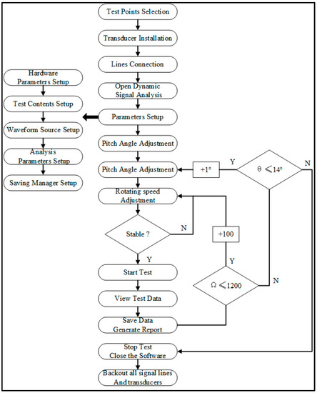
Figure 4.
Vibration measurement flow diagram.
The acquisition frequency of the dynamic signal analyzer is set to . The rotor speed is measured by the Hall speed sensor in order to adjust the stable rotor speed. The Hall speed sensor transmits the signal to the R7008SB receiver, and the R70-08SB receiver transmits the signal to the FUTABA T14SG, and the speed is displayed on the FUTABA T14SG interface. According to the displayed speed, the throttle stick is adjusted to achieve a stable rotor speed. The acceleration data are transmitted to the data acquisition and analyzer instrument, and the data analyzer transmits the signal to the computer, and the acceleration is displayed on the computer screen. After the rotor speed is stable, the acceleration data are collected and stored. The detailed connection diagram can be seen in Figure 5.
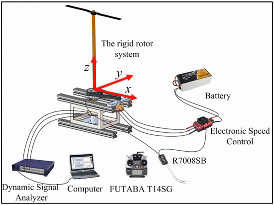
Figure 5.
Connection diagram of vibration measurement system.
2.4. Coordinate System and Measurement Accuracy
The fuselage of the fixed rotor system is used as the construction axis coordinate system. The origin is at the center of the rotor shaft. The x and y axes are parallel to the plane of the rotor, and the z axis is perpendicular to the plane and points upward, as shown in Figure 6. The sensitivity of the single-axis acceleration sensor EA-YD-185 is . The sensitivity of the three-axis acceleration sensor EA-YD-3193-5 is . The sampling frequency is set to , the sampling point is , and the frequency resolution is . After the original acceleration data are acquired, they are first transformed into the frequency domain spectrum by a fast Fourier transform (FFT) process. The time domain acquisition and frequency domain transform process are shown in Figure 6. The fuselage vibration acceleration of the model-scale rigid rotor is measured in the x, y, and z directions. Based on the vibration acceleration test data, the influence of the blade adjustment parameters (counterweight, pitch, trailing-edge flap) on the rigid-rotor dynamic balance is analyzed.

Figure 6.
The time domain acquisition and frequency domain transform process.
2.5. Rotor Blade Adjustment Parameters
In order to analyze the influence of rotor blade adjustment parameters on the fuselage vibration, the trailing-edge flap is an integral tab piece in the rotor dynamic balance test. The pitch is adjusted by the bolts fixing the blades on the hub; the counterweight is adjusted by the counterweight nut; the upward trailing-edge flap is negative and the downward trailing-edge flap is positive. The rotor adjustment parameters can be seen in Table 2.

Table 2.
Rotor adjustment parameters in this experiment.
The acceleration speed is measured under the following four conditions:
- (1)
- The rotor is adjusted to the dynamic balance state, the fuselage vibration data are measured at ;
- (2)
- Pitch: The rotor is adjusted to the dynamic balance state. Blade A pitch is set according to the pitch parameters in Table 2, and blade B pitch is set to 8°. The fuselage vibration data are measured at ;
- (3)
- Trailing-edge flap: The rotor is adjusted to the dynamic balance state. Blade A is added to the trailing-edge flap, which is set according to the trailing-edge flap parameters in Table 2;
- (4)
- Counterweight: The rotor is adjusted to the dynamic balance state. Blade A is added with counterweight, which is set according to the counterweight parameters in Table 2.
The 1 Ω vibration of the fuselage in the lateral, longitudinal, and vertical directions are measured and recorded under corresponding conditions.
3. Experiment Results and Discussion
Rotor vibration reduction is mainly achieved by rotor cone balance and rotor dynamic balance. The quality of rotor balance mainly refers to the level of vibration caused by the rotor and other rotating parts, usually aiming to reduce the helicopter’s 1 Ω vibration acceleration value.
Based on the analysis of rotor dynamic balance test data, the influence of rotor adjustment parameters (counterweight, pitch, trailing-edge flap) on fuselage vibration at different rotating speeds is obtained.
3.1. Waterfall Diagram of the Auto-Power Spectrum
The two aluminum alloy blades selected for the test are identical in shape and the mass error is within 0.01 g. The auto-power spectrum waterfall diagram of the fuselage at rotor speed 1000 r/min is analyzed. Figure 7 shows the waterfall diagram of the auto-power spectrum. It can be seen that the amplitude of low frequency (1~4 Ω) vibration is less than , which indicates that the rotor reaches the dynamic balance state.
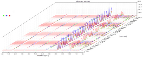
Figure 7.
Waterfall diagram of the auto-power spectrum for the dynamic balance state.
When the rotor is in work state, the counterweight adjustment has a greater impact on the vibration in the disc plane. If the rotor system consists of an even number of blades, the role of the blade-added counterweight is equivalent to that of the blade-reduced counterweight in relative position. Figure 8 shows the waterfall diagram of the fuselage auto-power spectrum caused by the counterweight. It can be seen that the amplitude of 1 Ω and 2 Ω vibration increases obviously when the counterweight is unbalanced.
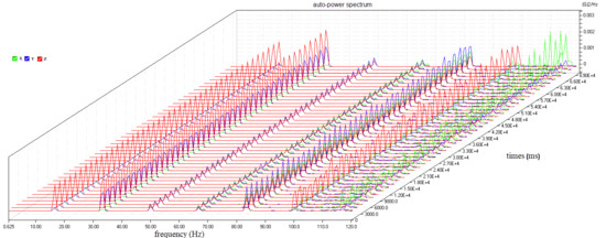
Figure 8.
Waterfall diagram of the auto-power spectrum for an unbalanced counterweight.
In order to improve the vertical vibration characteristics of the rotor, the rotor can be adjusted by changing the control input of the rotor aerodynamic force. One method is to adjust the pitch rod of the blade. The pitch rod is used to connect the automatic tilter and blade on the helicopter, which can control the pitch input of the corresponding blade. Changing the length of the pitch rod changes the attack angle of the blade, and the attack angle directly affects the lift of blade. It can be seen that if the rotor has a positive vertical force in a certain direction, then the pitch rod of the blade at the opposite position of 180° azimuth angle should be adjusted to change the pitch so that it can generate aerodynamic force with the same size and direction. Since the pitch rod on the helicopter cannot be dynamically adjusted, the pitch must be changed when the helicopter is hovering. Figure 9 shows the waterfall diagram of the fuselage auto-power spectrum caused by the pitch rod of the blade. It can be seen that the amplitude of 1 Ω and 2 Ω vibration increases obviously when the pitch is unbalanced.
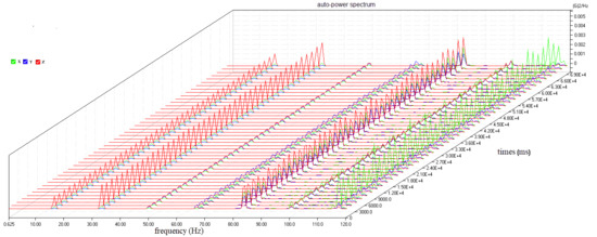
Figure 9.
Waterfall diagram of the auto-power spectrum for an unbalanced blade pitch.
The trailing-edge flap is another method to change the vertical vibration characteristics of the rotor system. The trailing-edge flap is similar to a swing device attached to the blade trailing edge. The adjustment method of the trailing-edge flap is the same as that for the aileron of a fixed-wing aircraft wing by changing the aerodynamic force attached to the blade. It can be seen that the camber of the airfoil segment with the trailing-edge flap reduces the lift when the flap is bent upward; on the contrary, the downward bending of the trailing-edge flap increases the lift of the blade in this section. Figure 10 shows the waterfall diagram of the fuselage auto-power spectrum caused by the trailing-edge flap. It can be seen that the amplitude of 1 Ω and 2 Ω vibration increases obviously when the trailing-edge flap is unbalanced.
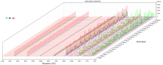
Figure 10.
Waterfall diagram of the auto-power spectrum for an unbalanced trailing-edge flap.
3.2. Influence of Counterweight on 1 Ω Vibration
Figure 11, Figure 12, Figure 13, Figure 14, Figure 15 and Figure 16 show the relationship between the counterweight and the amplitude and phase of the lateral, longitudinal, and vertical longitudinal 1 Ω vibration components at different speeds.
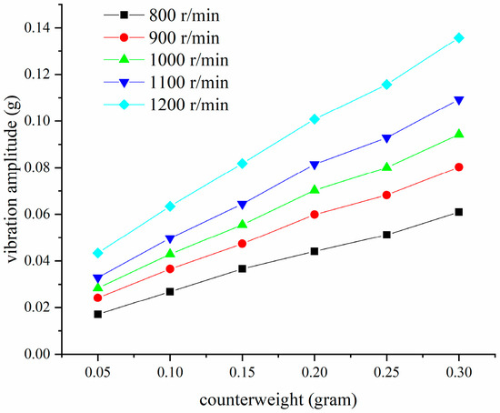
Figure 11.
Lateral amplitude diagram of counterweight.
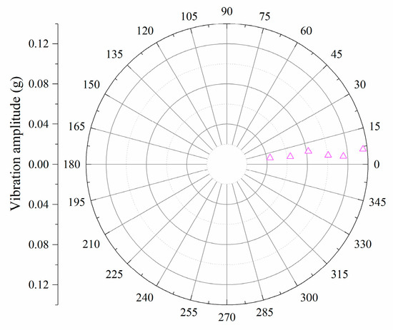
Figure 12.
Lateral polar diagram of counterweight.
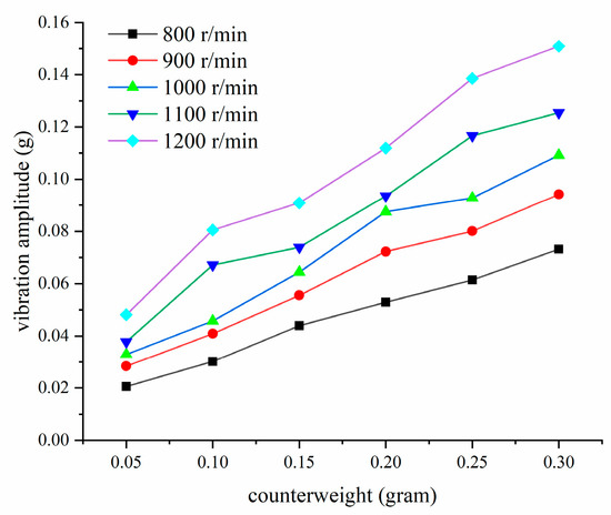
Figure 13.
Longitudinal amplitude diagram of counterweight.
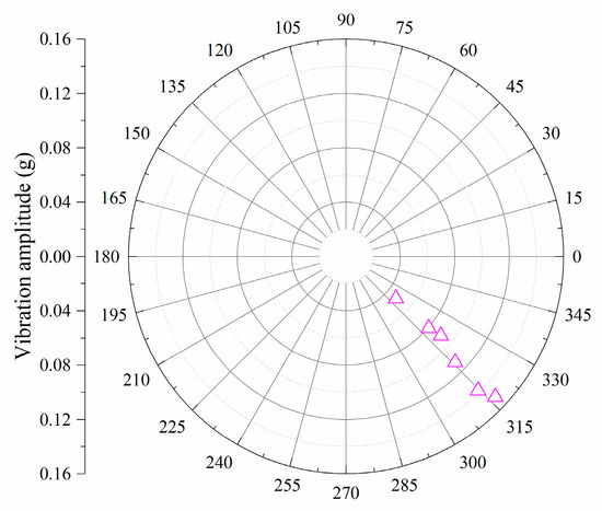
Figure 14.
Longitudinal polar diagram of counterweight.
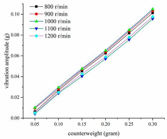
Figure 15.
Vertical amplitude diagram of counterweight.
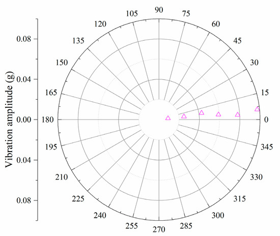
Figure 16.
Vertical polar diagram of counterweight.
It can be seen from Figure 11, Figure 12, Figure 13, Figure 14, Figure 15 and Figure 16 that with the increase in the counterweight of the same blade, the general trend of the amplitude of the 1 Ω vibration components in all directions of the fuselage is gradually increasing, and the initial phase is basically unchanged. However, there is a certain phase difference between the initial phases of the isotropic vibration. The amplitude of the 1 Ω vibration component of the fuselage in all directions does not change significantly with the speed, because the counterweight at the root of the hub has little influence on the centrifugal force.
3.3. Influence of Pitch on 1 Ω Vibration
Figure 17, Figure 18, Figure 19, Figure 20, Figure 21 and Figure 22 show the relationship between the pitch and the amplitude and phase of the lateral, longitudinal, and vertical longitudinal 1 Ω vibration components at different speeds.
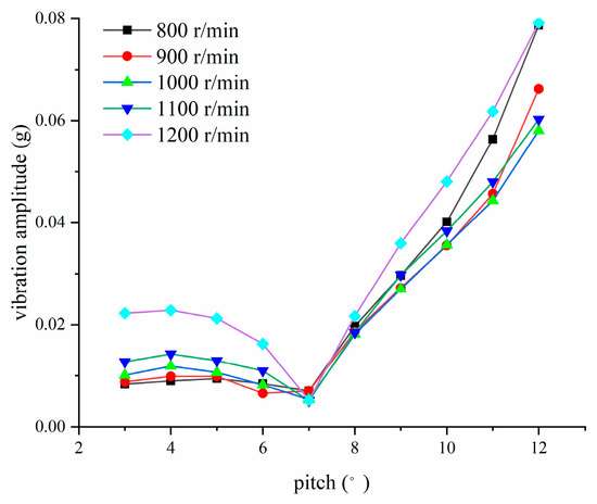
Figure 17.
Lateral amplitude diagram of pitch.
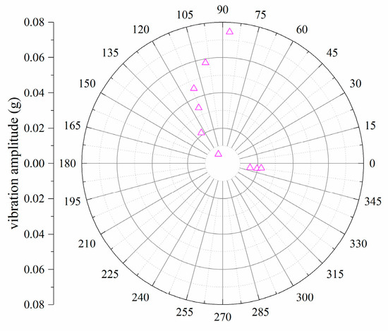
Figure 18.
Lateral polar diagram of pitch.
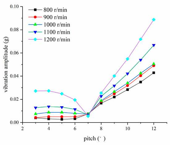
Figure 19.
Longitudinal amplitude diagram of pitch.
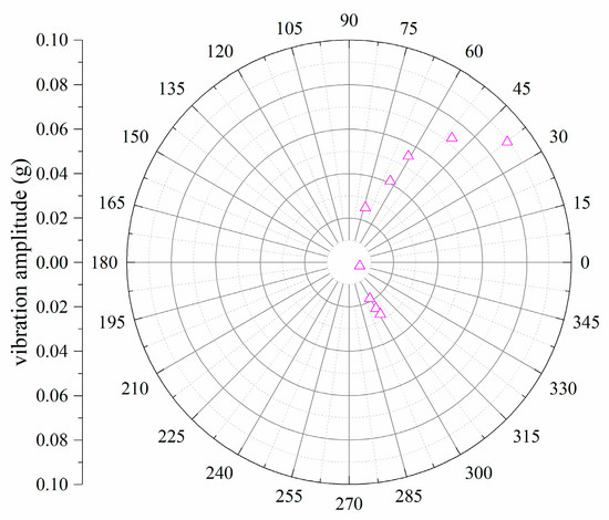
Figure 20.
Longitudinal polar diagram of pitch.
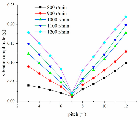
Figure 21.
Vertical amplitude diagram of pitch.
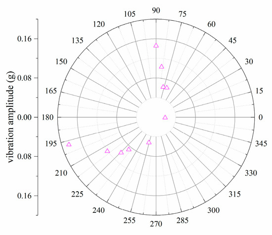
Figure 22.
Vertical polar diagram of pitch.
It can be seen from Figure 17, Figure 18, Figure 19, Figure 20, Figure 21 and Figure 22 that the vibration amplitude increases with the pitch. The unbalanced pitch has a great influence on the vertical vibration by the rotor speed. The unbalanced pitch has little influence on the lateral and longitudinal vibration by the rotor speed. The change in pitch has an obvious effect on the phase change. With the change in pitch, the phase first increases and then decreases.
3.4. Influence of Trailing-Edge Flap on 1 Ω Vibration
Figure 23, Figure 24, Figure 25, Figure 26, Figure 27 and Figure 28 show the relationship between the trailing-edge flap and the amplitude and phase of the lateral, longitudinal, and vertical longitudinal 1 Ω vibration components at different speeds.
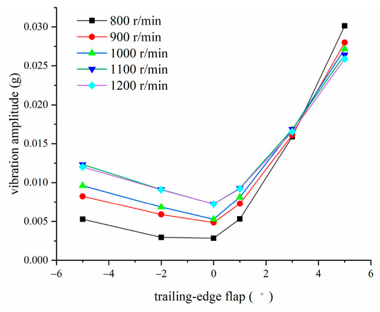
Figure 23.
Lateral amplitude diagram of trailing-edge flap.
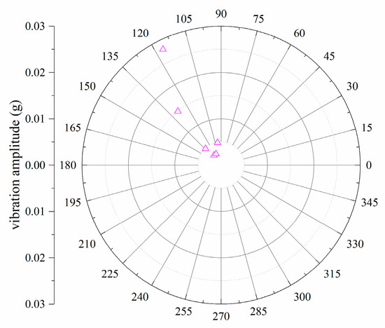
Figure 24.
Lateral polar diagram of trailing-edge flap.
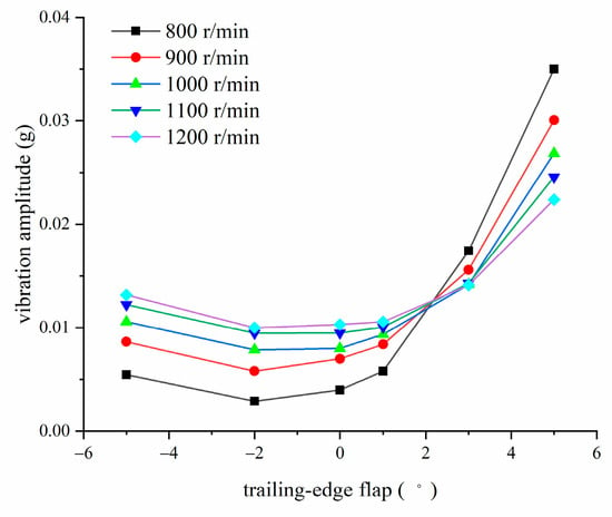
Figure 25.
Longitudinal amplitude diagram of trailing-edge flap.
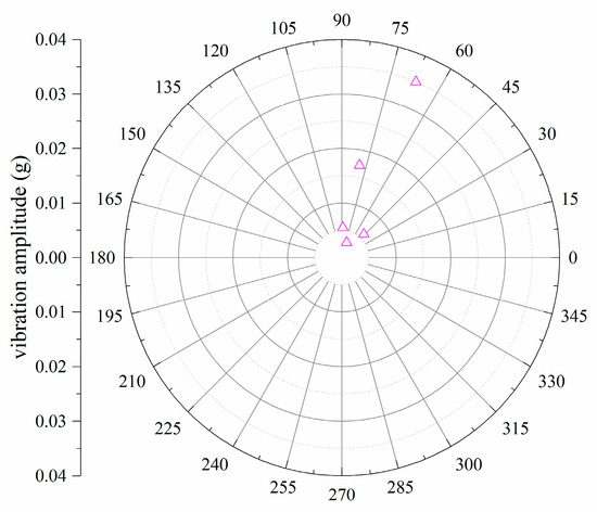
Figure 26.
Longitudinal polar diagram of trailing-edge flap.
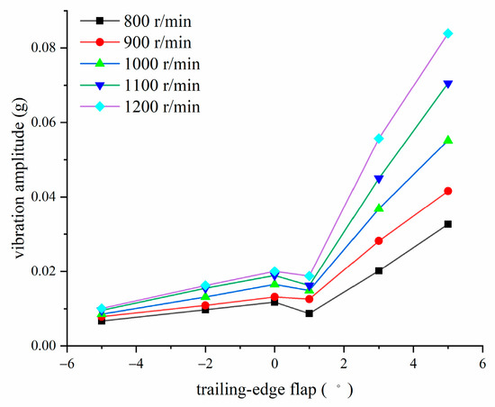
Figure 27.
Vertical amplitude diagram of trailing-edge flap.
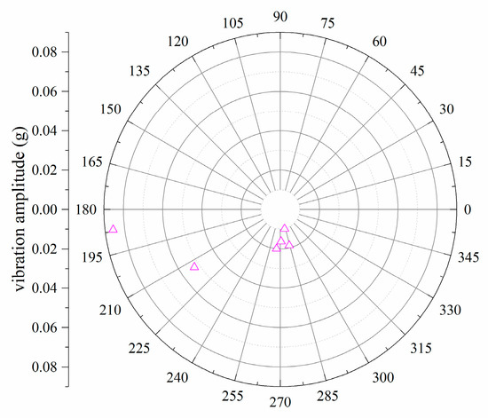
Figure 28.
Vertical polar diagram of trailing-edge flap.
It can be seen from Figure 23, Figure 24, Figure 25, Figure 26, Figure 27 and Figure 28 that the trailing-edge flap has little influence on the lateral and longitudinal vibration with roughly the same trend, but it has an obvious influence on the vertical vibration. Therefore, the trailing-edge flap has a significant effect on the vertical vibration. Under different rotor speeds, the curve dispersion is large, indicating that the trailing-edge flap is affected by the speed. This is because the higher the speed, the greater the aerodynamic imbalance force.
4. Conclusions
A dynamic balance test of a scale-model rigid rotor in hover was performed in the Key Laboratory of Ministry of Education at Beihang University; the results are described and reported in this paper. The experimental data are extracted by using all-phase fast Fourier transform. The influence of rotor adjustment parameters on the 1 Ω vibration components at different speeds is analyzed, and the following conclusions can be drawn:
- (1)
- The lateral and longitudinal vibration of the fuselage are greatly affected by the counterweight, but the counterweight effect on the vertical vibration is relatively small. The force generated by the counterweight is located in the disc plane, because the counterweight located at the root of the hub is less affected by rotor speed.
- (2)
- The vertical vibration of the fuselage is greatly affected by pitch, and the pitch has little influence on the lateral and longitudinal vibration of the fuselage. The pitch mainly affects the vertical aerodynamic force, which is greatly affected by rotor speed.
- (3)
- The vertical vibration of the fuselage is greatly affected by the trailing-edge flap, and the trailing-edge flap has little influence on the lateral and longitudinal vibration of the fuselage. The trailing-edge flap mainly affects the vertical aerodynamic force, which is greatly affected by rotor speed.
- (4)
- Concerning the dynamic balance adjustment of the variable speed rigid-rotor blade, the counterweight adjustment should be given the highest priority for the vibration in the disc plane, and the pitch and trailing-edge flap adjustment should be given the highest priority for the vertical vibration.
Author Contributions
L.L.: Conceptualization, methodology, validation, writing—review and editing, writing—original draft preparation, software, formal analysis. M.C.: resources, funding acquisition. F.W.: data curation, supervision, project administration. A.X.: investigation, data curation, visualization. All authors have read and agreed to the published version of the manuscript.
Funding
This research received no external funding.
Acknowledgments
This work is supported by the Key Laboratory of Ministry of Education at Beihang University and the Helicopter Research Laboratory. The authors are also greatly appreciative of the instructor, Ming Chen, for providing the dynamic signal analyzer and model-scale rotor setup and for helping with the experimental methods.
Conflicts of Interest
The authors declare no conflict of interest.
Nomenclature
| DAS | Data acquisition analysis |
| DSP | Digital signal processing |
| ESC | Electronic speed control |
References
- Iseler, L.; De Maio, J. Analysis of U.S. civil rotorcraft accidents from 1990 to 1996 and implications for a safety program. In Proceedings of the American Helicopter Societyl 57th Annual Forum, Washington, DC, USA, 9–11 May 2001. [Google Scholar]
- Taneja, N.; Wiegmann, D.A. Analysis of Injuries among Pilots Killed in Fatal Helicopter Accidents. Aviat. Space Environ. Med. 2003, 74, 337–341. [Google Scholar]
- Chen, Y.; Wickramasinghe, V.; Zimcik, D.G. Development of adaptive helicopter seat for aircrew vibration reduction. J. Intell. Mater. Syst. Struct. 2011, 22, 489–502. [Google Scholar] [CrossRef]
- Tamer, A.; Muscarello, V.; Masarati, P.; Quaranta, G. Evaluation of vibration reduction devices for helicopter ride quality improvement. Aerosp. Sci. Technol. 2019, 95, 105456. [Google Scholar] [CrossRef]
- Qi, X.; Qi, J.T.; Theilliol, D.; Zhang, Y.M.; Han, J.D.; Song, D.L.; Hua, C.S. A review on fault diagnosis and fault tolerant control methods for single-rotor aerial vehicles. J. Intell. Robot. Syst. 2014, 73, 535–555. [Google Scholar] [CrossRef]
- Rafiee, M.; Nitzsche, F.; Labrosse, M. Dynamics, vibration and control of rotating composite beams and blades: A critical review. Thin-Walled Struct. 2017, 119, 795–819. [Google Scholar] [CrossRef]
- Ece, M.C.; Aydogdu, M.; Taskin, V. Vibration of a variable cross-section beam. Mech. Res. Commun. 2007, 34, 78–84. [Google Scholar] [CrossRef]
- Ma, H.; Lu, Y.; Wu, Z.Y.; Tai, X.Y.; Li, H.; Wen, B.C. A new dynamic model of rotor-blade systems. J. Sound Vib. 2015, 357, 168–194. [Google Scholar] [CrossRef]
- Wang, A.M.; Bi, Y.J.; Feng, Y.; Yang, J.; Cheng, X.H.; Meng, G.Y. Continuous rotor dynamics of multi-disc and multi-span rotors: A theoretical and numerical Investigation of the Identification of rotor unbalance from unbalance responses. Appl. Sci. 2022, 12, 3865. [Google Scholar] [CrossRef]
- Hayden, R.E.; Ventres, C.S.; DiMarco, W.J.; Floyd, M.D. Method and Apparatus for Reducing Vibration over the Full Operating Range of a Rotor and a Host Device. U.S. Patent 4,937,758, 26 June 1990. [Google Scholar]
- Ganguli, R. A fuzzy logic system for ground based structural health monitoring of a helicopter rotor using modal data. J. Intell. Mater. Syst. Struct. 2001, 12, 397–407. [Google Scholar] [CrossRef]
- Pawar, P.M.; Ganguli, R. Genetic fuzzy system for online structural health monitoring of composite helicopter rotor blades. Mech. Syst. Signal Process. 2007, 21, 2212–2236. [Google Scholar] [CrossRef]
- Pawar, P.M.; Ganguli, R. Helicopter rotor health monitoring-a review. Proc. Inst. Mech. Eng. Part G-J. Aerosp. Eng. 2007, 221, 631–647. [Google Scholar] [CrossRef]
- Roy, N.; Ganguli, R. Helicopter rotor blade frequency evolution with damage growth and signal processing. J. Sound Vib. 2005, 283, 821–851. [Google Scholar] [CrossRef]
- Pawar, P.M.; Ganguli, R. On the effect of progressive damage on composite helicopter rotor system behavior. Compos. Struct. 2007, 78, 410–423. [Google Scholar] [CrossRef]
- Singh, H.K.; Pawar, P.M.; Ganguli, R.; Jung, S.N. On the effect of mass and stiffness unbalance on helicopter tail rotor system behavior. Aircr. Eng. Aerosp. Technol. 2008, 80, 129–138. [Google Scholar] [CrossRef]
- Ganguli, R. Health monitoring of a helicopter rotor in forward flight using fuzzy logic. AIAA J. 2002, 40, 2373–2381. [Google Scholar] [CrossRef]
- Ganguli, R.; Chopra, I.; Haas, D.J. Detection of helicopter rotor system simulated faults using neural networks. J. Am. Helicopter Soc. 1997, 42, 161–171. [Google Scholar] [CrossRef]
- Ganguli, R.; Chopra, I.; Haas, D. Simulation of helicopter rotor-system structural damage, blade mistracking, friction, and freeplay. J. Aircr. 1998, 35, 591–597. [Google Scholar] [CrossRef]
- Yeo, H.; Chopra, I. Coupled rotor/fuselage vibration analysis for teetering rotor and test data comparison. J. Aircr. 2001, 38, 111–121. [Google Scholar] [CrossRef]
- Yang, M.; Chopra, I.; Haas, D. Rotor system health monitoring using coupled rotor-fuselage vibration analysis. In Proceedings of the American Helicopter Societyl 56th Annual Forum, Virginia Beach, VA, USA, 2–4 May 2000. [Google Scholar]
- Alkahe, J.; Rand, O.; Oshman, Y. Helicopter health monitoring using an adaptive estimator. J. Am. Helicopter Soc. 2003, 48, 199–210. [Google Scholar] [CrossRef][Green Version]
- Wang, K.; Wang, S.; Liu, H. Optimal adjustment method of rotor multi-dimensional vibration. J. Beijing Univ. Aeronaut. Astronaut. 2010, 36, 1303–1306. [Google Scholar]
- Liu, H.; Lü, C.; Ouyang, P.; Wang, S. Helicopter rotor tuning based on neural network and particle swarm optimization. J. Beijing Univ. Aeronaut. Astronaut. 2011, 37, 283–288. [Google Scholar]
- Samuel, P.D.; Pines, D.J. A review of vibration-based techniques for helicopter transmission diagnostics. J. Sound Vib. 2005, 282, 475–508. [Google Scholar] [CrossRef]
- Wang, S.; Han, J.; Yun, H.; Chen, X. CFD-CSD method for coupled rotor-fuselage vibration analysis with free wake-panel coupled model. Proc. Inst. Mech. Eng. Part G J. Aerosp. Eng. 2020, 235, 1343–1354. [Google Scholar] [CrossRef]
- Lee, Y.-L.; Kim, D.-H.; Park, J.-S.; Hong, S.-B. Vibration reduction simulations of a lift-offset compound helicopter using two active control techniques. Aerosp. Sci. Technol. 2020, 106, 106181. [Google Scholar] [CrossRef]
- Ji, X.M.; Yang, M.; Ning, C.X. Reducing helicopter 1/rev vibration using extendable trailing-edge plate. Proc. Inst. Mech. Eng. Part G J. Aerosp. Eng. 2022, 236, 3064–3072. [Google Scholar] [CrossRef]
- Zhou, Z.X.; Huang, X.C.; Tian, J.J.; Hua, H.X.; Tang, M.; Wang, C. Numerical and experimental analysis on the helicopter rotor dynamic load controlled by the actively trailing edge flap. Smart Mater. Struct. 2022, 31, 035023. [Google Scholar] [CrossRef]
- Park, J.S.; Kim, D.H.; Chae, S.; Lee, Y.L.; Go, J.I. Vibration and performance analyses using individual blade pitch controls for lift-offset rotors. Int. J. Aerosp. Eng. 2019, 2019, 9589415. [Google Scholar] [CrossRef]
- Huang, J.; Yang, F. Development and challenges of electric aircraft with new energies. Hangkong Xuebao/Acta Aeronaut. Et Astronaut. Sin. 2016, 37, 57–68. [Google Scholar]
- Sziroczak, D.; Jankovics, I.; Gal, I.; Rohacs, D. Conceptual design of small aircraft with hybrid-electric propulsion systems. Energy 2020, 204, 117937. [Google Scholar] [CrossRef]
- Alexander, R.; Meyer, D.; Wang, J.K. A comparison of electric vehicle power systems to predict architectures, voltage levels, power requirements, and load characteristics of the future all-electric aircraft. In Proceedings of the IEEE Transportation and Electrification Conference and Expo (ITEC), Long Beach, CA, USA, 13–15 June 2018; pp. 194–200. [Google Scholar]
- Howse, M. All-electric aircraft. Power Eng. 2003, 17, 35–37. [Google Scholar] [CrossRef]
- Rohacs, J.; Rohacs, D. Energy coefficients for comparison of aircraft supported by different propulsion systems. Energy 2020, 191, 116391. [Google Scholar] [CrossRef]
- Johnson, W. Propulsion System Models for Rotorcraft Conceptual Design. In Proceedings of the Decennial AHS Aeromechanics Specialists, San Francisco, CA, USA, 22–24 January 2014. [Google Scholar]
- Datta, A.; Johnson, W. Requirements for a hydrogen powered all-electric manned helicopter. In Proceedings of the 12th AIAA Aviation Technology, Integration, and Operations (ATIO) Conference and 14th AIAA/ISSMO Multidisciplinary Analysis and Optimization Conference, Indianapolis, Indiana,, 17–19 September 2012; p. 5405. [Google Scholar]
- Xie, J.Y.; Xie, Z.F.; Zhou, M.; Qiu, J. Multidisciplinary aerodynamic design of a rotor blade for an optimum rotor speed helicopter. Appl. Sci. 2017, 7, 639. [Google Scholar] [CrossRef]
- Xie, J.Y.; Guan, N.X.; Zhou, M.; Xie, Z.F. Study on the mechanism of the variable-speed rotor affecting rotor aerodynamic performance. Appl. Sci. 2018, 8, 1030. [Google Scholar] [CrossRef]
- Xu, A.A.; Wang, F.; Chen, M.; Li, L. Aerodynamic modeling and performance analysis of variable-speed coaxial helicopter. Appl. Sci. 2022, 12, 9534. [Google Scholar] [CrossRef]
- Zhao, S.B.; Ren, X.M.; Deng, W.Q.; Lu, K.; Yang, Y.F.; Fu, C. A transient characteristic-based balancing method of rotor system without trail weights. Mech. Syst. Signal Processi. 2021, 148, 107117. [Google Scholar] [CrossRef]
- Zhao, S.B.; Ren, X.M.; Deng, W.Q.; Lu, K.; Yang, Y.F.; Li, L.H.; Fu, C. A novel transient balancing technology of the rotor system based on multi modal analysis and feature points selection. J. Sound Vib. 2021, 510, 116321. [Google Scholar] [CrossRef]
- Yimin, M.; Ming, C.; Xingwen, Z.; Qiang, W. Scale-model tests of coaxial rotors in water tunnel via particle image velocimetry technique. J. Aerosp. Eng. 2016, 230, 426–443. [Google Scholar]
- Meiliwen, W.; Ming, C. Nonlinear Modeling and Flight Validation of a Small-Scale Compound Helicopter. Appl. Sci. 2019, 9, 21. [Google Scholar] [CrossRef]
Publisher’s Note: MDPI stays neutral with regard to jurisdictional claims in published maps and institutional affiliations. |
© 2022 by the authors. Licensee MDPI, Basel, Switzerland. This article is an open access article distributed under the terms and conditions of the Creative Commons Attribution (CC BY) license (https://creativecommons.org/licenses/by/4.0/).