Abstract
In microbiochips and microfluidic devices, microholes are a basic and important feature. The microdrilling of glass materials without cracks is still challenging in the fabrication of glass-based microdevices. This paper investigates the characteristics of microdrilling fused silica using polycrystalline diamond (PCD) tools fabricated by electrical discharge machining (EDM). In particular, peak forces, which are observed at the beginning of drilling, are discussed because crack formations are related to peak forces. To reduce peak forces and to minimize cracks, the effects of drilling conditions, such as tool shape, the surface roughness of a tool, and axial feedrate, were therefore investigated. It was observed that D-shape tools with high surface roughness was useful to reduce the peak force. In through-hole drilling, a sacrificial layer was used to prevent exit cracks, and a variable feedrate was applied to increase drilling speeds. Finally, a dressing process using EDM was conducted to recondition the worn tool’s surface.
1. Introduction
In the field of microdevices, including microelectromechanical systems (MEMS), miniaturized total analysis systems (TAS), and microfluidic devices, glass substrates are needed because of their excellent mechanical hardness, electrical insulation, optical transparency, and chemical and thermal stability. However, the micromachining of glass is limited because glass is very hard.
Microholes are an important and basic feature for microdevices. Many researchers investigated the microdrilling of glass using various drilling techniques. Laser drilling, one of the most widely used methods, is a fast and direct single-step process. Chung and Lin [1] used a CO laser to produce a microhole array in Pyrex glass. Huang et al. [2] used a femtosecond fiber laser to produce microholes in soda-lime glass. Lee et al. [3] studied the machining characteristics of femtosecond laser helical drilling for aluminosiligate glass and borosilicate glass. However, the issue of a tapered hole with a heat-affected zone (HAZ) caused by thermal ablation remains a major problem. Etching techniques as a batch process are used mainly to fabricate micropatterns of glass materials. Li et al. [4] used deep reactive ion etching (DRIE) to fabricate microhole patterns of Pyrex glass. Iliescu et al. [5] used wet etching to fabricate a microfluidic device made of Pyrex glass. Nagarah and Wagenaar [6] used wet etching to produce microhole arrays in fused silica. However, these etching techniques still suffer from defects caused by the masking process, and an etchant such as hydrofluoric (HF) acid is hazardous to both the environment and humans. Electrochemical discharge machining (ECDM) is used to machine nonconductive materials. Zheng et al. [7] used ECDM to produce microholes in Pyrex glass. Nguyen et al. [8] used ECDM to produce microholes in Pyrex glass and quartz. In using this technique, however, gap control and the flushing of removed materials between the tool and the workpiece are difficult, and the heat affected zone led to tapered sidewalls and an overcut. Ultrasonic drilling is a suitable method for brittle materials. Egashira et al. [9] used ultrasonic drilling to produce microholes in borosilicate glass. Schorderet et al. [10] investigated the ultrasonic microdrilling of glass to produce deep microholes. Jain et al. [11] used microrotary ultrasonic machining to produce microholes in borosilicate. However, this technique has limitations, such as tool wear and low feedrates.
This study presents a mechanical drilling process that is cost-effective, simple, and well-suited for rapid prototyping with high-dimensional accuracy. However, since the machinability of mechanical drilling is limited by crack formations at the entrance and exit of holes, studies aimed at reducing and preventing crack formation have been conducted. Park et al. [12] used a back-up glass plate in the microdrilling of soda-lime glass. They proposed a method to attach soda-lime glass to a back-up plate with water in order to more effectively prevent exit cracks. Quan et al. [13] used a sintered diamond abrasive core tool and an electroplating diamond abrasive core tool in the drilling of soda-lime glass. They investigated the effect of drilling parameters on edge collapse at hole exits. Mizobuchi and Ogawa [14] used two kinds of electroplated tools to minimize crack sizes in the through-hole drilling of soda-lime glass. Ohzeki and Arai [15] developed a drilling system with feedback control based on cutting forces in order to prevent cracks in the drilling of borosilicate glass. Chen et al. [16] used a diamond tool with negative back rake angles to prevent crack formation at the entrance and a sacrificial pad to prevent exit crack formation in the drilling of optical glass and quartz. Mizobuchi et al. [17] used a back-tapered electroplated diamond tool when drilling soda-lime glass. The back-tapered tool was effective in reducing crack sizes and improving chip discharge efficiency.
In order to improve surface quality and accuracy in micromechanical machining, harder tools with high wear resistance are needed, because tool wear increases cutting force during machining. For this reason, PCD as the hardest tool material (except for a single crystal diamond tool) is suitable for the micromachining of hard, brittle materials [18]. Morgan et al. [19] used both conical and cylindrical PCD tools to machine microgrooves in soda-lime glass and micropockets in ultra-low expansion glass. They obtained smooth surfaces under ductile-regime machining and evaluated the wear of PCD tools. Suzuki et al. [20] fabricated microaspheric molds and dies in tungsten carbide using a PCD micromilling tool. Tungsten carbide was machined in the ductile mode, and the surface roughness was R 15 nm. Cheng et al. [21] used a PCD straight edge micromill to machine slots in tungsten carbide and silicon wafers. Katahira et al. [22] used a square PCD end mill to machine silicon carbide. Na et al. [18] used a PCD grinding tool to machine 3D microstructures in alumina and zirconia.
The research mentioned above mainly studied the mechanical drilling of general glasses, such as soda-lime and borosilicate. In contrast, the microdrilling of harder glass, such as fused silica, has yet been studied extensively. Fused silica has high hardness, low thermal expansion, and high chemical resistance [23]. Therefore, in this paper, the microdrilling of fused silica using PCD microtools was used to produce microholes with good edge quality and to improve drilling efficiencies.
2. Experimental Setup
For our experiments, microtools were fabricated by wire electro-discharge grinding (WEDG) [24,25]. Figure 1a shows a WEDG system and a schematic of region A. PCD rods containing diamond grains of 10 m were used. A PCD rod of ø 1 mm was clamped in a spindle and connected to a cathode as a workpiece. A brass wire was supported on a guide and connected to an anode as an electrode tool. The rod and wire were immersed in EDM oil. One hundred volts was applied between the rod and wire, and the rod was slowly fed in the z direction during drilling. The rod was shaped into a smaller rod of 300 m by means of a few operations, including rough and finishing cuts [18]. The EDM conditions are summarized in Table 1.
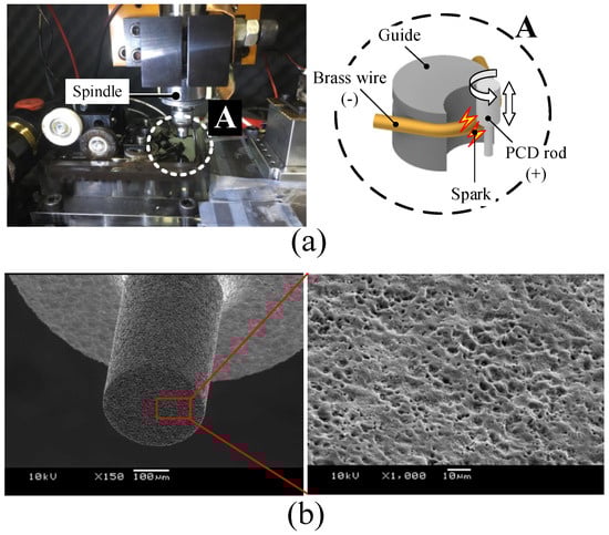
Figure 1.
Microtool fabrication: (a) WEDG system and (b) fabricated microtool.

Table 1.
EDM conditions.
The PCD rod was used as a microtool for microdrilling. The EDMed surface of the tool is rough and covered with craters of several micrometers created by sparks, as shown in Figure 1b. The rough surface serves as an abrasive in the grinding process; numerous craters consisting of diamond grains act as cutting edges [22].
Figure 2 shows a schematic of the microdrilling experiment. A PCD tool is fixed in a high-speed spindle mounted on the z-axis. The maximum rotational speed is 60,000 rpm. The fused silica used as a workpiece was placed on the dynamometer (9256C2, Kistler Instrumente AG, Winterthur, Switzerland), which was mounted on the x-y stage. Three components of drilling force were measured by a dynamometer in order to analyze drilling performances. The experiments were carried out with the drilling parameters of the axial feedrate ranging from 2 m/s to 30 m/s at a rotational speed of 50,000 rpm. The drilling conditions are summarized in Table 2. The machined holes and their surfaces were observed by means of scanning electron microscopy (SEM).
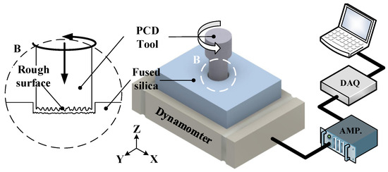
Figure 2.
Schematic illustration of the microdrilling experiment.
Table 2.
Microdrilling conditions.
3. Microdrilling Fused Silica
Figure 3 shows the drilling force measured during the microdrilling of fused silica using a PCD microtool. The PCD tool was cylindrical and flat, as shown in Figure 1b. The tool’s diameter was 300 m. The axial feedrate was 10 m/s and the tool’s rotational speed was 50,000 rpm. At the beginning of drilling, the thrust force (F) increased to its peak value (F), 8 N, and then decreased rapidly because of the contact stiffness between the tool and workpiece. In the grinding process, Yamada et al. [26] reported that the actual depth of cut is less than the applied depth of the cut because of the elastic deformation of the grinding wheel, which is associated with the contact stiffness. For this reason, the material was not removed until the thrust force reached F, at which time a crack occurred on the surface of the workpiece, which then began to be removed with a lower thrust force. As the peak force increases, the radial force (F and F) also increases to 1 N, leading to more edge chipping and tool breakage caused by the tool’s wobble. In this paper, therefore, effects of tool shape, tool surface roughness, and axial feedrate on peak force and hole quality were investigated.
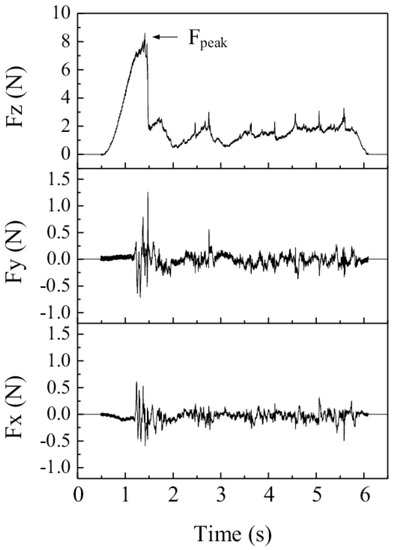
Figure 3.
Drilling force of microdrilling of fused silica using a micro-PCD tool.
3.1. Effect of Tool Shape
The shape of the tool influences the cutting force and surface quality [23]. To investigate the effect of tool shape on F, in this study, a cylindrical tool and D-shaped tools were used. Figure 4a is a SEM image of the D-shaped tool, which was fabricated by WEDG. Figure 4b shows the thrust forces in the drilling with a cylindrical tool and two D-shape tools of different width. Compared to the result of cylindrical tool, the F of D-shaped tools were lower, and thrust forces were more stable. This is because of the edge of the tools. At the edge of the D-shape tool, the workpiece can more easily crack; consequently, the force decreases. The D-shaped tool with a width of 180 m showed lower F than the case of 240 m. This is because the smaller bottom area of the tool causes higher stress and introduces cracks easily.
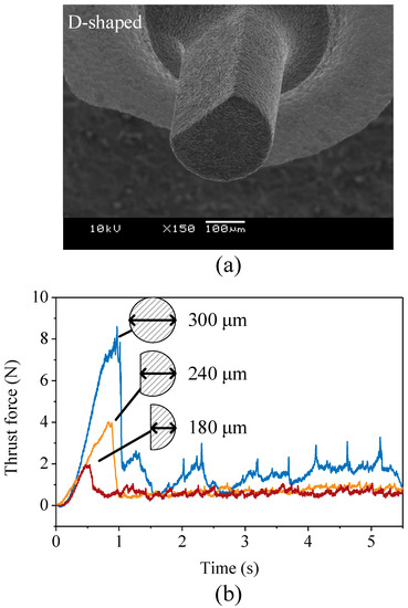
Figure 4.
(a) A SEM image of a D-shaped tool and (b) thrust forces according to tool shapes (drilling conditions: axial feedrate 10 μm/s; rotational speed of 50,000 rpm).
Since chip adhesion on the tool leads to high drilling force and cracks, chip discharge is important [27]. The D-shaped tool is effective not only for decreasing F but also for flushing out chips. An experiment to verify the chip-discharge effect was conducted with a D-shaped tool possessing a cut length that is shorter than the drilling depth. Figure 5 shows the thrust force and the position of the tool during drilling. A is where the cut length of the tool is longer than the drilling depth. Since the chip discharged effectively from the drilling zone, the thrust force was low and stable. B is where the length of the tool is shorter than the depth of hole. Therefore, the thrust force begins to increase because there is no space for chip discharges between the tool and the workpiece.
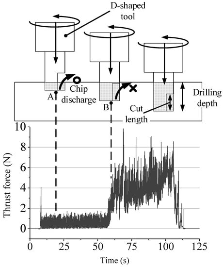
Figure 5.
Thrust force and tool position during drilling (drilling conditions: axial feedrate 5 μm/s; rotational speed of 50,000 rpm).
3.2. Effect of Tool Surface Roughness
To investigate the effect of the surface roughness of tool on drilling force, tools with various surface roughnesses were used. The surface roughness of a tool fabricated by EDM is related to the size of the craters and depends on the discharge energy. Jahan et al. [28] reported that discharge energy can be controlled by changing the capacitance in the EDM system using an RC circuit. Figure 6a shows the surface roughness of PCD tools in R and R according to different capacitances. As capacitance increases, the surface roughness increases. R was used for comparing how deep the craters are. The size of the craters is important because the craters act similarly to abrasives of a grinding wheel. Figure 6b,c show surfaces for 5600 pF and 770,000 pF. From these images, it is clearly seen that a high capacitance generates larger craters on the surface.
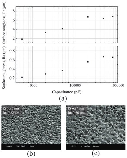
Figure 6.
(a) Surface roughnesses according to different capacitances, and SEM images of surfaces for (b) 5600 pF and (c) 770,000 pF.
With small abrasive grains, grinding forces increased, and with large grains, forces decreased [29]. Figure 7 shows F according to the surface roughnesses of the tools. F and its deviation show a tendency to decrease with increasing surface roughness. Figure 8 shows the results of two conditions. Figure 8a,b show the thrust forces in detail and drilled holes when the surface roughness is R 1.85 m and R 6.84 m, respectively. In Figure 8a, the peak force was about 30 N, the thrust force seemed unstable, and a large edge chipping of about 200 m in length was observed. On the other hand, in Figure 8b, the peak was much lower, the thrust force was more stable, and a clear edge was observed. From these results, it was confirmed that the surface roughness of the tool is an important factor affecting the drilling force and edge quality.
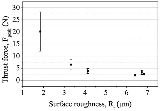
Figure 7.
Thrust force (F) according to different surface roughnesses.
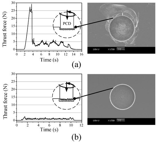
Figure 8.
Comparison of thrust forces and drilled holes for different surface roughness of tools; (a) Rt 1.85 μm and (b) Rt 6.84 μm (drilling conditions: axial feedrate 10 μm/s; rotational speed of 50,000 rpm).
3.3. Effect of Axial Feedrate
In the drilling process, the axial feedrate of tool is a main parameter that influences productivity. Because an excessive axial feedrate leads to increased drilling force and more edge chipping, a proper axial feedrate is required to increase the drilling speed with good edge quality. In order to verify the effect of axial feedrate on thrust force and edge quality, axial feedrates ranging from 2 m/s to 30 m/s were applied. Figure 9a shows a graph of F according to different axial feedrates. F increased from 1 N to 9 N as the axial feedrate increased. Figure 9b compares the SEM images of drilled holes with different axial feedrates. Clear edges were observed in the results of 2 m/s and 10 m/s, and the edge chippings in these were less than 10 m in length. Larger edge chippings occurred at 20 m/s and 30 m/s, with sizes of 50 m and 100 m, respectively. It was found that less than 10 m/s is needed to prevent large edge chipping.
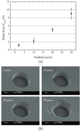
Figure 9.
(a) Thrust force according to different axial feedrates and (b) SEM images of machined holes with different tool feedrates (drilling condition: rotational speed of 50,000 rpm).
4. Through-Hole Drilling
4.1. Prevention of Exit Cracks
Even though low feedrate is applied, it is difficult to prevent exit cracks, because tensile stress affects the exit side when a tool is passing through the workpiece. Therefore, a sacrificial layer was used to reduce tensile stress and prevent exit cracks. A workpiece and sacrificial layer were fixed, as shown in Figure 10a–c show SEM images of the exit sides of drilled holes with and without a sacrificial layer. Large cracks occurred at the exit of a drilled hole without a sacrificial layer. By contrast, the result using the sacrificial layer shows much less edge chipping.
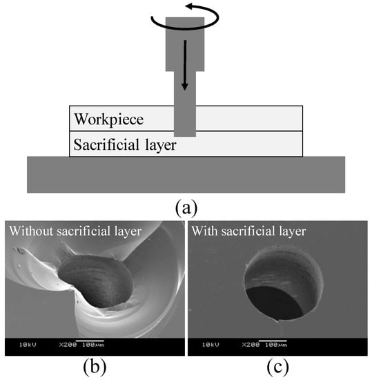
Figure 10.
(a) Microdrilling using a sacrificial layer, and (b,c) SEM images of the exit side of the through hole (drilling conditions: axial feedrate 5 μm/s; rotational speed of 50,000 rpm).
4.2. Variable Feedrates
Crack formations could be reduced by applying a low feedrate, but that takes more time. In this paper, variable feedrates were applied in order to increase drilling speeds without deteriorating hole quality. The through-hole drilling of 500 m in depth was conducted. The total drilling depth was divided into three regions of 20 m, 430 m, and 50 m, as shown in Figure 11a. In the first region of 20 m, a feedrate of 10 m/s, which is associated with good edge quality, was applied. In the second region of 420 m, a feedrate of 100 m/s was applied. Finally, a feedrate of 10 m/s was applied to the third region. Compared to the constant feedrate of 10 m/s across all three regions, drilling times could be reduced by 77%. Figure 11b shows a SEM image of a drilled hole. Edge chippings of about 15 m in length were observed.
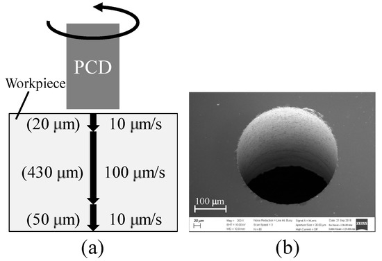
Figure 11.
(a) Schematic diagram of microdrilling using variable feedrates and (b) SEM image of drilled hole (drilling condition: rotational speed of 50,000 rpm).
5. Tool Wear and Dressing
Since tool wear increases the cutting force and adversely affects the hole’s quality, the evaluation of tool wear is necessary [30,31,32]. However, because PCD is an extremely hard material, very little wear occurs at the bottom of the tool, so it is difficult to measure wear length. In order to estimate the wear of PCD tools in this study, therefore, the drilling forces and the surface roughnesses of PCD tools were measured. Figure 12 shows the surface roughness of PCD tools according to the number of drillings. The surface roughnesses of the tools tended to decrease as the number of drillings increased. After drilling 200 holes, the surface roughnesses of the tools decreased from 0.66 m to 0.51 m in R. This means that tool wear occurred during drilling.
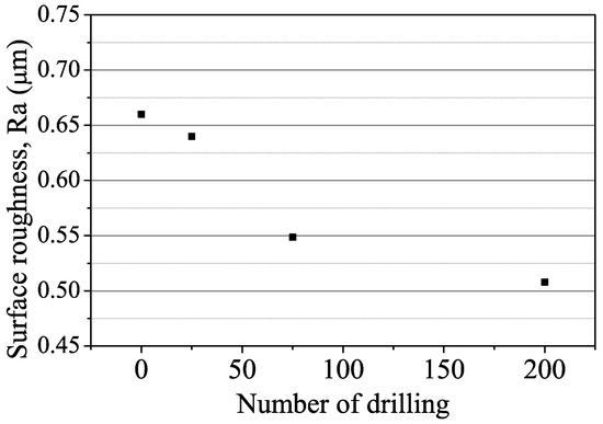
Figure 12.
Surface roughnesses of tools according to the numbers of drilling (drilling conditions: axial feedrate 10 μm/s; rotational speed pf 50,000 rpm; drilling depth of 200 m).
Tool life and machining performance are affected by tool wear. Therefore, dressing is required to improve tool life and to recover machining performances. In this study, EDM was used to make rough surface again. Since a simple D-shaped tool having a flat bottom was used, EDM dressing can be easily applied to the tool’s bottom.
Figure 13a shows average thrust forces according to the number of drillings. The force increased from 0.3 N to 0.6 N while drilling 200 holes, after which the dressing was applied, as shown in Figure 13b. Only the bottom surface of the tool was machined by EDM. The dressing conditions were 100 V and 470,000 pF and the dressing took 5 min. After dressing, thrust forces decreased from 0.6 N to 0.2 N. The tool performed again like a new tool because of the removal of the worn surface.
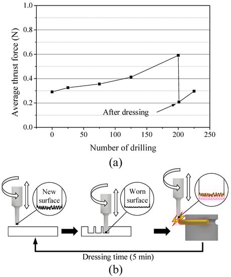
Figure 13.
(a) Thrust force according to the number of drillings and (b) dressing process using WEDG (drilling conditions: axial feedrate 10 μm/s; rotational speed of 50,000 rpm; dressing conditions: 100 V, 470,000 pF).
6. Discussions and Conclusions
The microdrilling of fused silica using D-shaped PCD tools was carried out in order to produce microholes. In this study, it was found that the peak thrust force was related to edge chipping. Therefore, we had to decrease the peak thrust force (F) in order to achieve good edge quality. Compared to a cylindrical tool, a D-shaped tool was effective in reducing peak force and improving chip-discharge efficiency. In addition to the tool’s shape, the surface roughness of the tool was also an important factor for reducing peak force. As the surface roughness of the tool increases, the peak thrust force decreases significantly. A variable feedrate was used to improve drilling speeds. A low feedrate was applied at the beginning of drilling to prevent edge chippings, and then a high feedrate was applied to increase drilling speeds. Consequently, drilling times could be reduced by 77% with maintaining edge quality. As the number of drillings increased, the surface of the tool became smoother and the thrust force increased. To make a rough surface again, EDM dressing was conducted. After dressing, the surface became as rough as that of a new tool, and thrust forces decreased. Electroplated microdrills also can be used to drill microholes in glass materials [14,17]. However, when electroplated abrasives are worn out, the tool cannot be used any more. In this study, since the tool’s shape is very simple and has a D shape, it is easy to regenerate the tool’s bottom surface by EDM dressing and this can increase the tool’s life. In addition, D-shaped tools having a flat bottom can be used not only in drilling but also in milling. It is expected that microholes and microchannels in glass-based microfluidic devices can be produced with a single PCD tool.
Author Contributions
Conceptualization and methodology, B.H.K. and P.A.L.; formal analysis, B.H.K. and P.A.L.; writing—original draft preparation, B.H.K.; writing—review, B.H.K.; supervision, B.H.K.; funding acquisition, B.H.K. All authors have read and agreed to the published version of the manuscript.
Funding
This work was supported by the Technology Innovation Program (20010984) funded by the Ministry of Trade, Industry and Energy (MOTIE), Korea.
Institutional Review Board Statement
Not applicable.
Informed Consent Statement
Not applicable.
Data Availability Statement
Not applicable.
Conflicts of Interest
The authors declare no conflict of interest.
References
- Chung, C.K.; Lin, S.L. CO2 laser micromachined crackless through holes of Pyrex 7740 glass. Int. J. Mach. Tools Manuf. 2010, 50, 961–968. [Google Scholar] [CrossRef]
- Huang, H.; Yang, L.M.; Liu, J. Micro-hole drilling and cutting using femtosecond fiber laser. Opt. Eng. 2014, 53, 051513. [Google Scholar] [CrossRef]
- Lee, H.M.; Choi, J.H.; Moon, S.J. Machining characteristics of glass substrates containing chemical components in femtosecond laser helical drilling. Int. J. Precis. Eng.-Manuf.-Green Technol. 2020, 8, 375–385. [Google Scholar] [CrossRef]
- Li, X.; Abe, T.; Liu, Y.; Esashi, M. Fabrication of high-density electrical feed-throughs by deep-reactive-ion etching of Pyrex glass. J. Microelectromech. Syst. 2002, 11, 625–630. [Google Scholar] [CrossRef]
- Iliescu, C.; Chen, B.; Miao, J. On the wet etching of Pyrex glass. Sens. A Ctuators Phys. 2008, 143, 154–161. [Google Scholar] [CrossRef]
- Nagarah, J.M.; Wagenaar, D.A. Ultradeep fused silica glass etching with an HF-resistant photosensitive resist for optical imaging applications. J. Micromech. Microeng. 2012, 22, 035011. [Google Scholar] [CrossRef]
- Zheng, Z.P.; Su, H.C.; Huang, F.Y.; Yan, B.H. The tool geometrical shape and pulse-off time of pulse voltage effects in a Pyrex glass electrochemical discharge microdrilling process. J. Micromech. Microeng. 2007, 17, 265. [Google Scholar] [CrossRef]
- Nguyen, K.H.; Lee, P.A.; Kim, B.H. Experimental investigation of ECDM for fabricating micro structures of quartz. Int. J. Precis. Eng. Manuf. 2015, 16, 5–12. [Google Scholar] [CrossRef]
- Egashira, K.; Mizutani, K.; Nagao, T. Ultrasonic Vibration Drilling of Microholes in Glass. CIRP Ann. 2002, 51, 339–342. [Google Scholar] [CrossRef]
- Schorderet, A.; Deghilage, E.; Agbeviade, K. Tool Type and Hole Diameter Influence in Deep Ultrasonic Drilling of Micro-Holes in Glass. Procedia CIRP 2013, 6, 565–570. [Google Scholar] [CrossRef]
- Jain, A.K.; Pandey, P.M. Study of Peck drilling of borosilicate glass with muRUM process for MEMS. J. Manuf. Process. 2016, 22, 134–150. [Google Scholar] [CrossRef]
- Park, B.J.; Choi, Y.J.; Chu, C.N. Prevention of Exit Crack in Micro Drilling of Soda-Lime Glass. CIRP Ann. 2002, 51, 347–350. [Google Scholar] [CrossRef]
- Quan, Y.M.; Liang, L.; Zhong, W.W. The Experimental Research on Small Hole Machining in Glass Using Diamond Abrasive Core-Tools. Adv. Mater. Res. 2009, 76–78, 491–496. [Google Scholar] [CrossRef]
- Mizobuchi, A.; Ogawa, H. Through-Hole Drilling of Glass Plate Using Electroplated Diamond Tool. Appl. Mech. Mater. 2011, 52–54, 384–388. [Google Scholar] [CrossRef]
- Ohzeki, H.; Arai, F. Drilling of Borosilicate Glass with Feedback Control Based on Cutting Force. Adv. Mater. Res. 2011, 325, 442–448. [Google Scholar] [CrossRef]
- Chen, S.T.; Jiang, Z.H.; Wu, Y.Y.; Yang, H.Y. Development of a grinding–drilling technique for holing optical grade glass. Int. J. Mach. Tools Manuf. 2011, 51, 95–103. [Google Scholar] [CrossRef]
- Mizobuchi, A.; Honda, K.; Ishida, T. Improved chip discharge in drilling of glass plate using back tapered electroplated diamond tool. Int. J. Precis. Eng. Manuf. 2017, 18, 1197–1204. [Google Scholar] [CrossRef]
- Na, Y.; Lee, U.S.; Kim, B.H. Experimental Study on Micro-Grinding of Ceramics for Micro-Structuring. Appl. Sci. 2021, 11, 8119. [Google Scholar] [CrossRef]
- Morgan, C.J.; Vallance, R.R.; Marsh, E.R. Micro machining glass with polycrystalline diamond tools shaped by micro electro discharge machining. J. Micromech. Microeng. 2004, 14, 1687. [Google Scholar] [CrossRef]
- Suzuki, H.; Moriwaki, T.; Yamamoto, Y.; Goto, Y. Precision Cutting of Aspherical Ceramic Molds with Micro PCD Milling Tool. CIRP Ann. 2007, 56, 131–134. [Google Scholar] [CrossRef]
- Cheng, X.; Wang, Z.; Nakamoto, K.; Yamazaki, K. Design and development of PCD micro straight edge end mills for micro/nano machining of hard and brittle materials. J. Mech. Sci. Technol. 2010, 24, 2261–2268. [Google Scholar] [CrossRef]
- Katahira, K.; Ohmori, H.; Takesue, S.; Komotori, J.; Yamazaki, K. Effect of atmospheric-pressure plasma jet on polycrystalline diamond micro-milling of silicon carbide. CIRP Ann. 2015, 64, 129–132. [Google Scholar] [CrossRef]
- Feng, K.; Lyu, B.; Zhao, T.; Yin, T.; Zhou, Z. Fabrication and Application of Gel-Forming CeO2 Fixed Abrasive Tools for Quartz Glass Polishing. Int. J. Precis. Eng. Manuf. 2022, 23, 985–1002. [Google Scholar] [CrossRef]
- Masuzawa, T.; Fujino, M.; Kobayashi, K.; Suzuki, T.; Kinoshita, N. Wire Electro-Discharge Grinding for Micro-Machining. CIRP Annals 1985, 34, 431–434. [Google Scholar] [CrossRef]
- Maeng, S.; Lee, P.A.; Kim, B.H.; Min, S. An Analytical Model for Grinding Force Prediction in Ultra-Precision Machining of WC with PCD Micro Grinding Tool. Int. J. Precis. Eng.-Manuf.-Green Technol. 2020, 7, 1031–1045. [Google Scholar] [CrossRef]
- Yamada, T.; Morgan, M.N.; Lee, H.S.; Miura, K. Calculation of the Contact Stiffness of Grinding Wheel. Adv. Mater. Res. 2011, 325, 54–59. [Google Scholar] [CrossRef]
- Mizobuchi, A.; Aziz, M.S.A.; Izamshah, R.; Ishida, T. Chip Discharge Performance of Micro-Hole Drilling through a Glass Plate using an Electroplated Diamond Tool with Different Drill Bits. Int. J. Precis. Eng. Manuf. 2018, 19, 1273–1280. [Google Scholar] [CrossRef]
- Jahan, M.P.; Wong, Y.S.; Rahman, M. A study on the quality micro-hole machining of tungsten carbide by micro-EDM process using transistor and RC-type pulse generator. J. Mater. Process. Technol. 2009, 209, 1706–1716. [Google Scholar] [CrossRef]
- Rowe, W.B. Chapter 5—Wheel Contact Effects. In Principles of Modern Grinding Technology; William Andrew Publishing: Boston, MA, USA, 2009; pp. 79–93. [Google Scholar] [CrossRef]
- Han, C.; Kim, K.B.; Lee, S.W.; Jun, M.B.G.; Jeong, Y.H. Thrust Force-Based Tool Wear Estimation Using Discrete Wavelet Transformation and Artificial Neural Network in CFRP Drilling. Int. J. Precis. Eng. Manuf. 2021, 22, 1527–1536. [Google Scholar] [CrossRef]
- Tao, S.; Gao, Z.; Shi, H. Characterization of Printed Circuit Board Micro-Holes Drilling Process by Accurate Analysis of Drilling Force Signal. Int. J. Precis. Eng. Manuf. 2022, 23, 131–138. [Google Scholar] [CrossRef]
- Svinth, C.N.; Wallace, S.; Stephenson, D.B.; Kim, D.; Shin, K.; Kim, H.Y.; Lee, S.W.; Kim, T.G. Identifying Abnormal CFRP Holes Using Both Unsupervised and Supervised Learning Techniques on In-Process Force, Current, and Vibration Signals. Int. J. Precis. Eng. Manuf. 2022, 23, 609–625. [Google Scholar] [CrossRef]


Publisher’s Note: MDPI stays neutral with regard to jurisdictional claims in published maps and institutional affiliations. |
© 2022 by the authors. Licensee MDPI, Basel, Switzerland. This article is an open access article distributed under the terms and conditions of the Creative Commons Attribution (CC BY) license (https://creativecommons.org/licenses/by/4.0/).