Abstract
Modal analysis and structural parameters selection are essential in the structural design of the crossbeam of a gantry machine tool. In order to explore an efficient modal analysis method, the analytical method of modes of the beam with variable cross-section is derived based on the Euler beam theory and transfer matrix method. By dividing the machine tool crossbeam into 27 segments, the crossbeam modes are obtained analytically, which is validated by the finite element method. Compared with the FEM, the analytical method shows high efficiency. On this basis, the influence of various structural parameters, including bending stiffness and linear density, on the crossbeam mode is explored, and the sensitivity analysis is carried out. The results show that the first-order bending frequency of the crossbeam is mainly affected by the bending stiffness in the middle part of the crossbeam, followed by the linear density in the middle and end part. The first-order bending frequency of the crossbeam increases by increasing the bending stiffness in the middle part and decreasing the linear density of the crossbeam. The linear density both in the middle and end part has a great effect on the mode shape of the crossbeam. This study can provide a reference and method for structural design and modal analysis of machine tool crossbeams.
1. Introduction
Machine tools used in manufacturing and production constitute the most important status in most industries nowadays [1,2]. The gantry machine tool has the characteristics of large processing span and high processing efficiency, which is suitable for batch or high-precision processing and has been widely used in the manufacturing industry [3,4,5]. The crossbeam of a gantry machine tool mainly withstands the vibration caused by the milling head, and its dynamic performance has an important impact on the performance of the machine tool. When the low-order mode is triggered by external excitation, the crossbeam will have significant elastic vibration, which directly affects the precision of the machining. Therefore, the structural design and vibration of the machine tool crossbeam have become a research focus by more and more scholars. Besharati et al. [6] investigated the influence of crossbeam and column parameters on the gantry machine tool by using sensitivity analysis. Zhou et al. [7] used the finite element method to analyze the static and dynamic characteristics of crossbeams with different rib plate shapes. Zhao et al. [8] carried out a structural bionic optimization design for the stiffening rib of a gantry machine tool crossbeam based on giant waterlily veins. Gao et al. [9] optimized the crossbeam of a bridge gantry milling machine, so the anti-vibration performance was improved. Qiu et al. [10] proposed an orthogonal experimental design method and gray correlation method for the lightweight design of a machine tool crossbeam, and increased the first-order natural frequency. Liu et al. [11] optimized the first four natural frequencies of the crossbeam by using gray correlation analysis and the Analytic Hierarchy Process. Li et al. [12] proposed a sensitivity analysis for optimizing the structural parameters of a machine tool crossbeam and used neural networks to improve the beam.
The above research mainly applies the finite element method (FEM) and various mathematical algorithms to study and optimize the machine tool crossbeam. Of course, the FEM is an efficient method to analyze the dynamic performance of structures [12]. However, in practice, it is found that the mesh discretization and finite element simulation of the crossbeams are repetitive works in the design. In addition, the size of the gantry machine tool crossbeam is very large, resulting in the reduction in the design efficiency inevitably. Therefore, the motivation for this paper is to obtain a convenient analytical method of the crossbeam modal analysis, to reduce the workload of the design. In fact, the analytical method of the beam mode is widely used in other engineering fields. Yang et al. [13] set-up an analytic calculation method for the first-order vertical bending frequency of a car-body structure based on Timoshenko beam theory. Similarly, Yang et al. [14] regarded the train body as a Euler beam and solved its mode shape by the analytical method. Mutman [15] used the Homotopy Perturbation Method (HPM) to study the free vibration of a Euler beam resting on elastic foundations and gave analytical solutions for different boundary problems. Shin et al. [16] gave a similar conclusion. Wang et al. [17] regarded the machine tool spindle as a stepped cantilever beam, and derived its modal solution based on Euler beam theory.
Thus, one of the purposes of this paper is to apply beam vibration theory to the modal analysis of the machine tool crossbeam. According to the beam vibration theory, the modal parameters of the beam with equal cross-section can be obtained by Bernoulli–Euler beam theory or Timoshenko beam theory. However, the cross-sectional shape of the machine tool crossbeam usually changes along the axial direction of the crossbeam. In view of the vibration of the beam with variable cross-section, many scholars have proposed different solutions. For instance, Cui et al. [18] studied the box structure with variable cross-section and applied analytical methods to the optimization of the structure design. It is common method to interpolate or approximate the solution. Liu et al. [19] presented the spline finite point method (SFPM) to study the free transverse vibration of tapered Euler beams, in which the cubic spline function was used to interpolate the displacement function. Firouz-Abadi et al. [20] obtained the solution of the differential equation of motion of the Euler beam by using the Wentzel–Kramers–Brillouin (WKB) expansion series. In addition, the transfer method was also applied to analyze the free vibration of a tapered beam and study the influence of different taper degrees on the beam mode [21].
In this paper, analytical solutions of the beam mode with variable cross-section are derived based on the Euler beam theory and transfer matrix method. Then, the crossbeam of the gantry machine tool is divided into several segments to solve the natural frequency and mode shape. The accuracy of the analytical solution is confirmed by the FEM, with less computation cost. According to the segmented beam model, the influence of the end and middle parameters of the crossbeam on its natural frequency and mode shape is discussed, and the sensitivity analysis is carried out, which provides a basis for the design of the machine tool beam.
2. Bernoulli–Euler Beam with Variable Cross-Section
2.1. Differential Equation of Motion
In the case of small deformation, for the Euler beam with equal cross-section, the differential equation of transverse motion is as follows:
where is the bending stiffness of the beam, is the linear density of the beam, and is the transverse deflection function of the beam.
The general solution of this equation is
where is the natural frequency of the beam, is the mode shape function of transverse free vibration of the beam, and .
When the beam with variable cross-section is divided into different segments according to the cross-sectional shape, each segment can be considered as a free vibrating beam with equal cross-section, so it follows the motion relation in Equation (1). Assuming that the variable-cross-section beam with a total length of L is divided into n segments, as shown in Figure 1, the mode shape function of the i-th segment beam is
where , , , , and is the natural frequency of the beam with variable cross-section. If the structural and the division method of the beam with variable cross-section are determined, the unknowns in the mode shape function of the beam are the natural frequency and the mode shape coefficient.
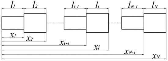
Figure 1.
The model of a beam with variable cross-section.
The displacement, angle, moment, and shear force of two adjacent segment beams are continuous at the joint [22], so the boundary relation between the i-th segment beam and i+1-th segment beam can be obtained as
Simplifying Equation (5), the transfer matrix of the adjacent segment beams can be established as follows:
where and is as follows:
Thus, the boundary relationship between the first segment beam and the N-th segment beam can be obtained:
where .
2.2. Boundary Condition and Solution
For the beam with free ends, the moment and shear force at both ends are zero:
Substituting Equation (8) into Equation (4), it can be obtained that
where .
Substituting Equation (7) into Equation (9), the boundary equation is obtained:
where .
The determinant of the coefficient matrix of Equation (10) must be zeros for all nontrivial solutions. Thus, it can be written as
The root of Equation (11) is the natural frequency of the crossbeam with variable cross-section. Then, substituting the natural frequency into Equation (10), the mode shape coefficients and of the first segment beam can be solved. By using the transfer relation given in Equation (6), the mode shape coefficient of the whole beam with variable cross-section can be obtained. However, in order to facilitate the modal analysis of the crossbeam, the mass normalization of the mode shape function should be carried out. The modal mass of the beam with variable cross-section is
The modal shape function of the beam with variable cross-section after the mass normalization is as follows:
As can be seen from the derivation process, the advantage of the analytical method based on the Euler beam theory and transfer matrix method is that it has strong programmability and adaptability for various problems. In actual application, it should be noted that this analytical method is not accurate enough for higher-order modes, due to Bernoulli–Euler beam theory ignoring the influence of shear deformation and the moment of inertia. Fortunately, modal analysis of machine tool crossbeams mainly focuses on the low-order modes, and it is suitable for this.
3. Crossbeam of Gantry Machine Tool: Analytical Solutions
3.1. Crossbeam Properties and Cross-Section Parameters
As described above, the crossbeam is an important component in the gantry machine tool. The structural and anti-vibration properties of the crossbeam have a direct impact on the stiffness and machining precision of the gantry machine tool [11]. Therefore, modal analysis should be carried out in the design of the machine tool beam. In this section, we apply the analytical method, which is derived in Section 2, to the modal analysis of the crossbeam. A five-axis machine tool, as shown in Figure 2, is mainly made up of a column, crossbeam, saddle, ram, and milling head. As can be seen in the figure, the crossbeam connects the columns and saddle, which receives the excitation from the milling head in the X and Y directions. Therefore, in the design of the crossbeam, the bending mode of the crossbeam in both directions should be computed and analyzed.
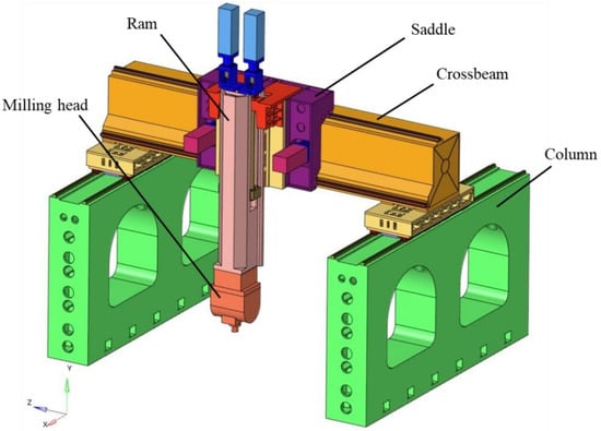
Figure 2.
Three-dimensional model of a five-axis machine tool.
Next, we focus on the properties of the crossbeam in the gantry machine tool. The crossbeam model and its profile are shown in Figure 3. The crossbeam material is structural steel with a density of 7850 kg/m3, an elastic modulus of 2.1 × 10¹¹ Pa, and a Poisson’s ratio of 0.3. It should be pointed out that the crossbeam model has been simplified to eliminate some features that have little influence on the modal parameters, such as chamfering and small holes. As the profile shown in Figure 3b, the crossbeam is welded by multiple metal plates. The crossbeam profile is composed of multiple feature surfaces, which gives the opportunity to use the equation in Section 1 by dividing the crossbeam. According to the shape of its section, 27 segments of the beam with 4 different section shapes can be divided. The position of each cross-section is marked in Figure 3b. The crossbeam division is shown in Figure 3c. Each divided segment beam can be considered as a beam with equal cross-section, and its length and position are marked in the figure. The crossbeam has four different cross-sectional shapes, as shown in Figure 4. It should be noted that there are several segment beams with the same cross-sectional shapes. For example, the 1st and 27th segment beams share Section-a; the 2nd and 6th segment beams share Section-b; the 3rd and 7th segment beams share Section-c; the 4th and 8th segment beams share Section-d.
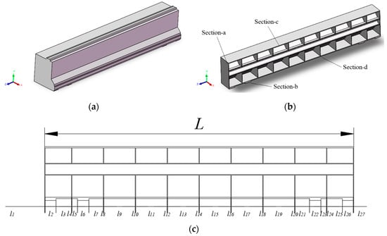
Figure 3.
Crossbeam profile: (a) crossbeam model; (b) crossbeam profile; (c) crossbeam division.

Figure 4.
Cross-sectional shapes of crossbeam: (a) Section−a; (b) Section−b; (c) Section−c; (d) Section−d.
When calculating the moment of inertia of different cross-sections, it is necessary to take into account that the centroid position of each cross-section is different. The parallel-axis formula is used to modify the moment of inertia of different cross-sections to the axis where the center of mass of the crossbeam is located. The parallel-axis formula is as follows:
where and are the moments of inertia through the centroid, and are the moments of inertia through the X and Y axes, and are the distances from the centroid to the X and Y axes, and is the cross-sectional area.
3.2. Analytical Solutions
The efficiency and precision of the analytical method derived in Section 2 are next validated by the FEM. The first is the mode result obtained by the analytical method. The natural frequency and mode shape of the crossbeam can be obtained by solving Equations (11) and (13). The first-order bending frequencies in the X and Y directions of the crossbeam are 142.94 Hz and 182.27 Hz, respectively. The corresponding mode shapes are shown in Figure 5. Typically, the finite element model of the crossbeam is established to verify the accuracy of the analytical method, which is simulated by commercial software ABAQUS. The 3D shell elements with thickness are employed to simulate the crossbeam. The first-order bending frequencies in the X and Y directions by the FEM are 146.77 Hz and 181.99 Hz, respectively. The corresponding mode shapes are shown in Figure 6.
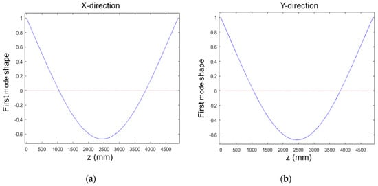
Figure 5.
Analytical mode shape of crossbeam: (a) X−direction; (b) Y−direction.
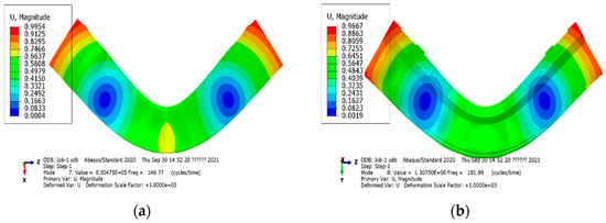
Figure 6.
FEM mode shape of crossbeam: (a) X−direction; (b) Y−direction.
Once shown the result by two methods, we focus on the precision of the analytical method. The relative error, which can be obtained by , is presented in Table 1. It can be seen from the table that the errors of the analytical method and FEM solutions of the first-order bending frequencies in the X and Y directions are less than 5%. In addition, the normalized mode shapes of the two methods match well. It can be concluded that the analytical solutions are consistent with the FEM solution. Remarkably, it only takes about 10 s to solve the first-order bending frequency and mode shape by MATLAB software. In contrast, the FEM takes about 4 h in simulation especially without the time of establishing the finite element model. By comparing the two methods, it is prominent that the analytical method is significantly more efficient than the FEM. Therefore, it is convenient to explore the influence of structural parameters on crossbeam modes by using analytical methods due to its high efficiency.

Table 1.
Analytical mode and FEM mode.
4. Influence of Structural Parameters on Crossbeam Mode
4.1. Structural Parameters Analytical Solutions
The influence of various structural parameters on crossbeam modes is discussed in this section. Prior to that, however, it should be noted that, in order to avoid repeated interpretation, only the Y-direction mode of the crossbeam is analyzed in this section due to the similarity of the influence of structural parameters on crossbeam modes in both directions. It can be obtained from Equation (1) that the crucial factors affecting the crossbeam mode are linear density and bending stiffness. In addition, the vibration of the gantry machine tool is transmitted from the saddle to the crossbeam and then to the column at the sides. Thus, in the crossbeam design, we pay more attention to the structural parameters in the end and middle parts of the crossbeam. The research in this section focuses on the influence of linear density and bending stiffness in the end and middle part of the crossbeam on the bending mode. As can be seen from Figure 3, cross-sections with different shapes are staggered in the crossbeam profile. In order to analyze the influence of structural parameters in the ends and middle part, the crossbeam model should be treated to some extent. Hence, the 27-segment crossbeam model is equivalent to the 3-segment crossbeam model, where the end part segments include segments 1 to 7 and 21 to 27, and the middle part segment includes segments 8 to 20. The linear density and bending stiffness in the end part and middle part are linearly averaged and the correction coefficient is taken to modify the 3-segment crossbeam model. The correction expression is as follows:
The comparison of the results of the 3-segment crossbeam model and the 27-segment crossbeam model is shown in Table 2. The corrected model has a low error, so the 3-segment crossbeam model can replace the 27-segment crossbeam model in this analysis.

Table 2.
Comparison of 3-segment beam model and 27-segment beam model.
After validating the analytical method, we next analyze the crossbeam mode to explore the influence of the various structural parameters on the mode. The trend of crossbeam mode with the structural parameters in the middle part of the crossbeam is shown in Figure 7. The arrow direction in the figure represents the increase in the structural parameter. It can be seen from Figure 7 that the first-order natural frequency of the crossbeam increases obviously with the increase in the bending stiffness in the middle part. The linear density in the middle part of the crossbeam has the opposite trend. Compared with the bending stiffness, the linear density in the middle part of the crossbeam has a lower impact on the natural frequency, and, however, the effect on the modal node position has the opposite result. With regard to the mode shape in the right figure, the modal node span decreases with the increase in the linear density in the middle part of the crossbeam. The increase in the bending stiffness in the middle part will lead to the increase in the modal node span, but this change is much weaker than that of the linear density.
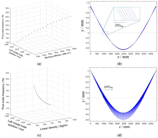
Figure 7.
The crossbeam mode versus the structural parameters in the middle part: (a) mode versus the bending stiffness; (b) mode shape versus the bending stiffness; (c) mode versus the linear density; (d) mode shape versus the linear density.
The trend of crossbeam mode with the structural parameters in the end part of the crossbeam is shown in Figure 8. Something noticeable can be observed from Figure 8. Compared with the results of the bending stiffness in the middle part of the crossbeam, it appears that the coupling between the natural frequency and the bending stiffness in the end part is weak. In addition to the above differences, the other influence degree of the structural parameters in the end parts is basically consistent with the structural parameters in the middle part, but the change direction of the crossbeam mode shape is reverse. It can be concluded from the results that it is easier to adjust the crossbeam mode shape by modifying the linear density in both the end and middle part of the crossbeam. This is good information because modulating weights in crossbeam design is usually more achievable. Another piece of information obtained from the comparison is that each structural parameter has a different influence degree on the crossbeam mode. We elaborate more the sensitivity of the crossbeam mode to various structural parameters below.
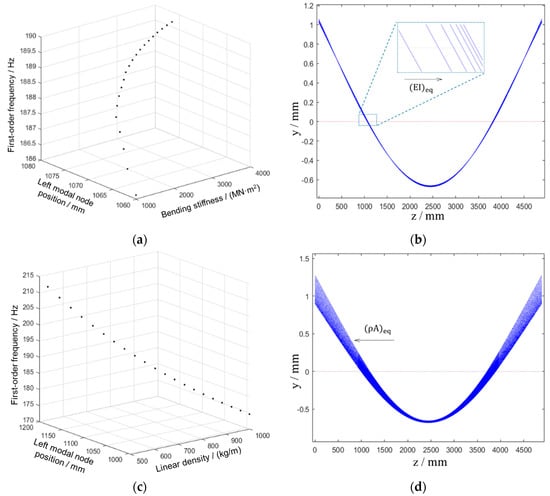
Figure 8.
The crossbeam mode versus the structural parameters in the end part: (a) mode versus the bending stiffness; (b) mode shape versus the bending stiffness; (c) mode versus the linear density; (d) mode shape versus the linear density.
4.2. Sensitivity Analysis
The sensitivity analysis of the crossbeam structure is carried out to determine the crucial parameters affecting the performance of the crossbeam, which can effectively aid an engineer to evaluate and prioritize the structural parameters of the crossbeam in the design. In this section, we choose the relative sensitivity analysis method. The four structural parameters analyzed in the previous section are selected as independent variables, and the first-order frequency and left modal node position are the dependent variables. By decreasing the independent variable by 10%, the relative sensitivities to various structural parameters, , are computed, which are presented in Table 3 and Figure 9.

Table 3.
Sensitivities value.
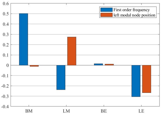
Figure 9.
Sensitivities of the crossbeam mode to structural parameters.
From the sensitivity analysis results, it can be known that the sensitivity of the various structural parameters to the modal performance of the crossbeam is different obviously. Both the bending stiffness in the middle and end part of the crossbeam have little effect on the mode shape, as shown in Figure 9. The main factor determining the mode shape of the crossbeam is the linear density. The bending stiffness in the middle part of the crossbeam has the greatest impact on the first-order frequency, followed by the linear density in the middle and end part. It is also obtained that the bending stiffness in the end part of the crossbeam has little influence on the crossbeam mode, so it can be considered as a secondary factor in the design.
5. Conclusions
In this study, the analytical method of the beam mode with variable cross-section is derived, and modal analysis of the crossbeam of a gantry machine tool based on the analytical method is carried out and the following results are obtained:
- Based on the Euler beam theory and transmission matrix method, the analytical method of the beam mode with variable cross-section is deduced. By dividing the crossbeam of the gantry machine tool into 27 segments according to the different cross-sectional shapes, the analytical solutions of the crossbeam mode are obtained, which are validated by the finite element method. Comparing with the FEM, the analytical method has advantages in terms of computational efficiency.
- By using the analytical method due to its high efficiency, the influence of the structural parameters on the crossbeam mode is investigated. Increasing the linear density in the middle part leads to the decrease in the modal node span of the crossbeam, while increasing the linear density in the end part leads to the opposite result. The bending stiffness in the end and middle of the crossbeam has a very low influence on the mode shape.
- The sensitivities of various structural parameters to the crossbeam mode are obtained separately. The results show that the main factor affecting the first-order frequency of the crossbeam is the bending stiffness in the middle part of the crossbeam, followed by the linear density in the middle and end part. The bending stiffness in the end part of the crossbeam barely makes a difference to the crossbeam mode.
- This study provides an efficient method for the crossbeam modal analysis, which is expected to be widely used in the design of the machine tool crossbeams. The next step is to optimize the structural parameters of the crossbeam. However, the analytical method of the crossbeam mode is only suitable for the analysis of low-order modes because Euler beam theory ignores the influence of shear deformation and the moment of inertia. Therefore, increasing the precision of the high-order mode of the crossbeam will be the future research focus.
Author Contributions
This study was initiated and designed by X.L. and Y.C.; the derivation of formulas, numerical simulations, and writing the paper were completed by X.L. and Y.C.; X.S. provided suggestions for paper writing and simulations. All authors have read and agreed to the published version of the manuscript.
Funding
This study was partly supported by the National Natural Science Foundation of China (52275092).
Institutional Review Board Statement
Not applicable.
Informed Consent Statement
Not applicable.
Data Availability Statement
The data are part of an ongoing project.
Conflicts of Interest
The authors declared no potential conflict of interest with respect to the research, authorship, and/or publication of this article. The authors declare no conflict of interest.
References
- Cheng, Q.; Zhao, H.; Zhao, Y.; Sun, B.; Gu, P. Machining accuracy reliability analysis of multi-axis machine tool based on Monte Carlo simulation. J. Intell. Manuf. 2018, 29, 191–209. [Google Scholar] [CrossRef]
- Yang, J.; Ding, H.; Zhao, H.; Yan, S. A generalized online estimation algorithm of multi-axis contouring errors for CNC machine tools with rotary axes. Int. J. Adv. Manuf. Technol. 2015, 84, 1239–1251. [Google Scholar] [CrossRef]
- Zhang, D.; Wang, L.; Gao, Z.; Su, X. On performance enhancement of parallel kinematic machine. J. Intell. Manuf. 2013, 24, 267–276. [Google Scholar] [CrossRef]
- Guo, S.; Jiang, G.; Mei, X. Investigation of sensitivity analysis and compensation parameter optimization of geometric error for five-axis machine tool. Int. J. Adv. Manuf. Technol. 2017, 93, 3229–3243. [Google Scholar] [CrossRef]
- Cheng, Q.; Luo, R.; Gu, P.; Wang, Z.; Guo, H. Load Induced Error Identification and Camber Curve Design of a Large-Span Crossbeam. Adv. Mech. Eng. 2013, 5, 847194. [Google Scholar] [CrossRef]
- Besharati, S.R.; Dabbagh, V.; Amini, H.; Sarhan, A.A.; Akbari, J.; Hamdi, M.; Ong, Z.C. Multi-objective selection and structural optimization of the gantry in a gantry machine tool for improving static, dynamic, and weight and cost performance. Concurr. Eng. 2016, 24, 83–93. [Google Scholar] [CrossRef]
- Zhou, L.; Yuan, J.; Wang, Z. Analysis and Optimization of the Structural of Beam in the Planer Type Machines. Mach. Des. Manuf. 2014, 1, 15–17. [Google Scholar]
- Zhao, L.; Chen, W.; Ma, J. Structural bionic optimization of stiffening ribs of a machine tool crossbeam based on giant waterlily vein distribution. Chin. High Technol. Lett. 2008, 18, 806–810. [Google Scholar]
- Gao, Z.; Qiu, Z.; Ren, D.; Cui, D.; Xu, X. Structure design and optimization for crossbeam of bridge gantry milling machine. Chin. J. Eng. Des. 2019, 26, 56–64. [Google Scholar]
- Qiu, Z.; Ju, J.; Ren, D.; Cui, D.; Liu, C. Optimization design for the crossbeam of a machining tool based on the orthogonal experimental method and combination weight-grey relational analysis. J. Vib. Shock 2017, 36, 105–111. [Google Scholar]
- Liu, S.; Li, Y.; Liao, Y.; Guo, Z. Structural optimization of the cross-beam of a gantry machine tool based on grey relational analysis. Struct. Multidiscip. Optim. 2014, 50, 297–311. [Google Scholar] [CrossRef]
- Li, X.; Li, C.; Li, P.; Hu, H.; Sui, X. Structural Design and Optimization of the Crossbeam of a Computer Numerical Controlled Milling-Machine Tool Using Sensitivity Theory and NSGA-II Algorithm. Int. J. Precis. Eng. Manuf. 2021, 22, 287–300. [Google Scholar] [CrossRef]
- Yang, G.; Gao, Y.; Wan, B. Analytic Analysis of the First Order Vertical Bending Frequency of Carbodies. Roll. Stock 2015, 53, 1–6. [Google Scholar]
- Yang, S.; Li, F.; Shi, H.; Wu, P. Effect of Modal Node Position of Vertical Bending of Car Body on Its Vibration. J. Mech. Eng. 2020, 56, 210–218. [Google Scholar]
- Mutman, U. Free Vibration Analysis of an Euler Beam of Variable Width on the Winkler Foundation Using Homotopy Perturbation Method. Math. Probl. Eng. 2013, 2013, 1–9. [Google Scholar] [CrossRef]
- Shin, Y.; Yun, J.; Seong, K.; Kim, J.; Kang, S.W. Natural frequencies of Euler-Bernoulli beam with open cracks on elastic foundations. J. Mech. Sci. Technol. 2006, 20, 467–472. [Google Scholar] [CrossRef]
- Wang, M.; Qin, P.; Zhang, Y.; Gao, X. Solution and Application for Vibration Characteristics of Combined Stepped Beam. J. Beijing Nuiversity Technol. 2019, 45, 1–7. [Google Scholar]
- Cui, D.; Li, D.; Zhou, S. Optimum design of variable cross-section bending–twisting coupled boxed structure based on multicoupled laminates. Int. J. Mech. Mater. Des. 2022, 18, 567–585. [Google Scholar] [CrossRef]
- Liu, P.; Liu, H.; Lin, K.; Qin, R. Free transverse vibration analysis of tapered bernoulli-euler beams based on spline finite point method. J. Vib. Shock 2016, 35, 66–73. [Google Scholar]
- Firouz-Abadi, R.D.; Haddadpour, H.; Novinzadeh, A.B. An asymptotic solution to transverse free vibrations of variable-section beams. J. Sound Vib. 2007, 304, 530–540. [Google Scholar] [CrossRef]
- Lee, J.W.; Lee, J.Y. Free vibration analysis using the transfer-matrix method on a tapered beam. Comput. Struct. 2016, 164, 75–82. [Google Scholar] [CrossRef]
- Cui, C.; Li, Y. A Solution for Vibration Characteristic of Timoshenko Beam with Variable Cross-section. J. Dyn. Control 2012, 10, 258–262. [Google Scholar]
Publisher’s Note: MDPI stays neutral with regard to jurisdictional claims in published maps and institutional affiliations. |
© 2022 by the authors. Licensee MDPI, Basel, Switzerland. This article is an open access article distributed under the terms and conditions of the Creative Commons Attribution (CC BY) license (https://creativecommons.org/licenses/by/4.0/).