Abstract
The clearance of a kinematic pair will lead to the contact collision between the joints of the mechanism, which will have a great influence on the dynamic characteristics of a mechanical system with clearance. In order to study the influence of a rotating motion pair with clearance on the dynamic characteristics of a tool changing robot, a contact wear dynamics model of a modular tool changing robot was established based on the three-state model of “free-contact-collision”. Different from analysis of a light linkage structure, this paper takes a solid structure with large mass as the analysis object. Based on the impact contact force model and the improved Coulomb friction model, the effects of clearance size, rotational speed and friction coefficient on the dynamic characteristics of the tool changing robot were analyzed. The Archard wear model was used to predict the wear between the motion pairs with clearance. The analysis results show that, with the increase of clearance size and actuating speed, the fluctuation range of velocity and acceleration increases, and the fluctuation frequency decreases. Under the action of friction, the contact force between components will be reduced due to energy loss so that the kinematic reliability of the mechanism is improved. The wear of the moving pair with clearance is non-uniform. Through the research of this paper, the motion characteristics of the tool-changing robot at low speed and heavy load are clarified. The results show that the established method can realize the dynamic characteristics analysis of low-speed heavy-duty mechanisms with joint gaps, which can be used to guide the design of tool-changing robots, and also has important reference significance for the design of mechanisms containing joint gaps in general.
1. Introduction
Shield machines are widely used in fields such as rail transportation and water facilities. Shield machine hobs are a class of wearing parts that need to be replaced frequently, but replacing hobs usually requires operation under pressure, so there is a great danger. The application of a tool-changing robot for tool replacement is a feasible method. The tool-changing robot is a multi-degree of freedom system. The robot will leave necessary clearances at the joints to complete the machining assembly and meet certain relative motion requirements. Unnecessary clearances will also be generated at the joints due to limitations of machining accuracy during the manufacturing process. The extent of clearance can seriously affect the mechanism’s motion accuracy and motion characteristics [1,2,3]. Therefore, the influence of joint clearance on the motion characteristics of the tool-changing robot needs to be analyzed. In the process of analyzing the dynamic characteristics of the mechanism with clearance, it is necessary to establish a motion model that can accurately and logically describe the dynamic characteristics of the contact collision at the clearance joints and the corresponding mathematical model of the contact force [4,5,6,7].
The collision models for mechanisms with clearance can be summarized into the following three categories: continuous contact model, two-state model, and three-state model [8,9,10,11,12,13]. Earles et al. [14] first proposed a continuous contact-based model arguing that the two components are always in continuous contact, so that it is possible to define the mechanism with clearance as a multi-link mechanism and establish the differential equations of motion for the whole system. Based on the L-N model and the improved Coulomb friction model, Flores et al. [15] investigated the effect of the number of rotating pairs with clearance and clearance size on the dynamic characteristics of the crank slider. Muvengei et al. [16] studied a crank-slider mechanism based on the L-N model, neglecting the tangential friction at the gap hinge, and analyzed the influence of the input speed and the position where the clearance occurs on the kinematic parameters of the mechanism during operation. Varedi et al. [17] optimized the design of the rod mass based on a particle swarm optimization algorithm and found that the optimized dynamic performance of the mechanism improved significantly. Shi et al. [18] established a contact force collision model with clearance by vector analysis method and used it for the dynamic characteristics analysis of a turbine valve mechanism. Zhao et al. [19] investigated the dynamics and dynamic wear characteristics of a two-axis-position mechanism of satellite antennas with joint clearance based on a non-linear spring damping model. Efremenkov et al. [20] studied the effect of cycloid reducer rolling body clearance on motion accuracy. Based on the L-N model, Hao et al. [21] investigated the influence of material characteristics of the two different components on the kinematic characteristics of a crank-slider mechanism with clearance, considering the effect of frictional forces at the clearance. Xu et al. [22] investigated the dynamic characteristics of the crank-slider mechanism containing deep groove ball bearing with clearance based on Hertz contact theory and continuous contact force model, and verified the correctness of the theoretical modelling with ADAMS. Fateh et al. [23] present a novel robust decentralized control of electrically driven robot manipulators. The proposed control employs a voltage control strategy, which is simpler and more efficient than the conventional torque control strategy, due to being free from manipulator dynamics. Xin et al. [24] developed an error model of translational manipulator based on motion/force transferability. The effect of motion/force transferability on the theoretical accuracy is revealed. Based on the established error model, the accuracy evaluation index is proposed and used for the accuracy optimization of the parallel manipulator by the tension synthesis method. The comparison of before and after optimization shows that the optimized parallel manipulator has a higher degree of simulation. Pereira et al. [25] discussed the effect of dry friction and proposed a contact law. Guo et al. [26] used the substructure method to analyze the contact-impact in the structure, and verified the validity of the model.
There has been a great deal of research into the problem of wear and tear during contact collision in joint mechanisms with clearance. Wei et al. [27] established the clearance dynamics model containing the number of clearances and the friction coefficient variables, and analyzed the dynamic characteristics of the crank-slider mechanism with clearance for the rod elastic deformation. Zhao et al. [28] investigated the effects of clearance hinges on deployment and motion processes of solar panels based on the L-N model and the Coulomb friction model. Using the ANSYS secondary development module, Su et al. [29] characterized the component wear by the movement of the boundary nodes, built a dynamics model with clearance contact and simulated the complex wear process. Zhao et al. [30] studied the kinematic reliability analysis of a planar parallel manipulator over time, taking into account joint clearance, input uncertainty and manufacturing defects based on the first-pass method. First, the limit state pose error function was established. Then, based on this, the kinematic reliability of the system over time was calculated under the assumption that the hybridization events were independent.
As a new type of robot, the shield machine tool-changing robot has not yet been seen in actual use. The working object of the shield machine tool-changing robot is the disk cutter of a shield machine. The weight of a disk cutter is about more than 300 kg. Therefore, the working condition of the robot is characterized by low speed and heavy load, and wear and low-speed impact are the key factors to be considered. In this paper, the kinematics and dynamics analysis is carried out to study in detail the influence of wear and impact on the motion characteristics of the tool-changing robot in the presence of joint clearance, in order to provide a basis for the design and reliability analysis of the tool-changing robot.
2. Models about Joint with Clearance
2.1. Model of Kinematic Pairs with Clearance
In the case of rotating joints with clearance, two kinematic constraints are removed, and two degrees of freedom are introduced. The forces working on the shaft pin and sleeve control the dynamics of joints including contact-impact processes. Consequently, there is a requirement for accurate modelling of the contact-impact process in the joint clearance to combine the clearance model with a kinetic model [31,32,33,34].
A rotating joint with clearance is shown in Figure 1a and the radial clearance is defined as follows:
where and are the radius of the shaft pin and sleeve, respectively.
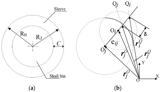
Figure 1.
The relationship between shaft pin and sleeve: (a) Rotating pair with clearance; (b) Contact between shaft pin and sleeve.
Figure 1b, and indicate the centers of the bearing and journal. and are the position vectors of the shaft pin and sleeve in the overall inertia coordinates, respectively. Thus, the clearance vector in Figure 1b is represented as follows:
The eccentricity of the clearance vector can be expressed as:
The unit normal vector where the contact between the shaft pin and sleeve occurs at the clearance is expressed as
can be used to determine whether the shaft pin and sleeve are in contact, the movement contact condition between the shaft pin and sleeve can be given by Equation (5):
2.2. Contact Force Model
The impact contact force model depicts the contact collision of two components in clearance by a spring-damping model and considers non-linear contact deformations [35,36,37]. The model describes not only the elastic forces due to contact collisions and elastic deformation of the components but also the tangential forces because of relative motion, which is particularly adapted to the working conditions of heavy loads and low speed. The normal contact force function is expressed as:
and
where is the material stiffness contribution, generally taken as 1.5; indicates the penetration depth of the two contact components, generally taken as 0.01 mm; is the damping parameter depending on the material properties, generally taken as , and is the stiffness value.
2.3. Friction Model
Due to the clearance between the shaft pin and sleeve, tangential friction is generated in the relative motion and it is, therefore, necessary to consider the influence of friction when analyzing the collision dynamics of structures with clearance. The improved Coulomb friction model assumes that dynamic friction occurs at the joint clearance when the friction coefficient is related to the tangential velocity [38,39,40]. As shown in Figure 2, the friction coefficient remains constant when the tangential velocity reaches the critical velocity. This friction model can be expressed as follows:
where is an odd function.
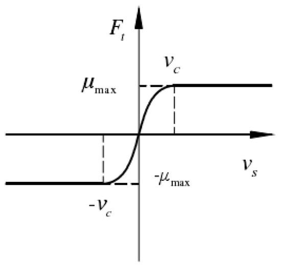
Figure 2.
Modified Coulomb friction model.
3. Wear Characteristics of Rotating Pairs with Clearance
3.1. Archard Wear Model
Due to the joint clearance, the direction of contact is considered to be the same as the forced direction in contact collisions, and the forced direction in the kinematic pair remains the same regardless of the presence of the clearance. This paper uses the Archard wear model to analyze the wear of a tool-changing robotic joint with clearance [41,42,43], which is expressed as:
where V is the wear volume, S is the relative slip distance, K is the dimensionless friction coefficient, Fn is the normal collision force and H is the Brinell hardness of the material (HBW).
It can be seen from Equation (9) that the Archard wear model takes into account the relationship between wear and slip distance, collision force and material properties, in which the wear is proportional to slip distance and normal collision force. Dividing both sides of Equation (9) by the nominal contact area at the same time, the following equation is obtained.
where h is the wear depth, p = Fn/A is the contact stress, and k = K/H is the linear wear coefficient.
From Equations (9) and (10), it can be seen that both the relative slip distance S and the contact force F are instantaneous values. In order to describe the change in wear depth precisely, Equation (10) is expressed in differential form as follows:
where h is the wear depth, p is the contact stress at the contact joint, k = K/H is the linear wear coefficient and ds = v ∗ dt.
The total wear of a node within a simulation step can be found by Equation (11), and the wear of the entire wear process can be derived by the discrete method:
where and are the wear of node n in the i and i−1 simulation steps, is the incremental slip distance in the ith simulation step and pi is the contact pressure in the ith simulation step.
Integration of Equation (12) gives the total wear and thus predicts the entire wear process.
3.2. Determination of Wear Calculation Parameters
Figure 3 shows the relative motion of the rotating pair as the shaft pin is moving in the sleeve. The radius of the shaft pin is R2, the angular velocities of the shaft pin and sleeve are ω2 and ω1 respectively, and the relative angular velocity of the shaft pin and sleeve is ω12, as expressed in Equation (13):
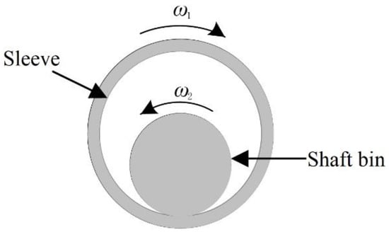
Figure 3.
Schematic diagram of the relative movement of the rotating pair.
The relative slip distance can be calculated from the relative slip velocity and the integration step, as shown in Equation (14).
where is the elastic deformation at the discrete point i of the contact interface between the shaft pin and sleeve, which can be calculated from the maximum elastic deformation .
According to the characteristics of the shaft pin and sleeve in the contact process, this process is made discrete, and each small area of contact is set as continuous after discretizing. The contact stress and the normal contact force are set in the same direction and the magnitude is calculated according to Hertz contact theory, which can significantly simplify the calculation with the following equation:
where F is the collision contact force (N), B is the length (m) of initial contact line, and are the curvature radius of the sleeve and shaft pin, respectively.
Therefore, the contact stress is expressed as follows:
where R1 and R2 are the radius of the sleeve and shaft pin, respectively.
4. Dynamic Characteristics of Mechanism with Clearance
4.1. Determination of Wear Calculation Parameters
This paper is based on a modular tool-changing robot in which all rotary joints, except rotary joint 5, are made up of oscillating hydraulic cylinders so that the accuracy of movement meets the working requirements. Because of being comprised of the shaft pin and sleeve, the clearance collision and wear analysis is carried out on the rotating joint 5.
Joint 5 is composed of bushings and journals. Ideally, the rotary joint is in nominal position and in free-flight motion without contact between journals and bearing elements. However, depending on the magnitude of the radial and axial play, several different contact situations may occur between the bearing and journal surfaces, as shown in Figure 4. The contact or movement between the journal and the bushing depends on the configuration of the dynamic system and the radial and axial play. Therefore, a three-dimensional joint gap model is established in this paper, fully considering the simultaneous action of axial movement, radial offset and spatial deflection. Figure 5a shows a real tool-changing robot we designed and Figure 5b is the 3D simulation model of the tool-changing robot built in ADAMS.
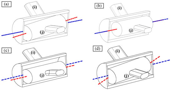
Figure 4.
Different states of the journal in the sleeve. (a) horizontal deflection. (b) pan horizontally. (c) vertical translation. (d) vertical deflection.
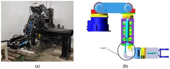
Figure 5.
The shield machine tool-changing robot. (a) Real robot. (b) 3D simulation model.
Based on the 3D simulation model of the tool-changing robot, in order to investigate the effects of different clearance parameters of the rotating joint on the kinematic characteristics, a dynamics simulation analysis of a mechanism with clearance and an ideal mechanism was carried out by setting different clearance parameters in ADAMS. The initial clearance size is set at 0.1 mm and the shaft pin of joint 5 is in the central position of the sleeve. The variation curve of mechanism motion parameters in the case of joints with clearance is shown in Figure 6. Figure 5b shows the simulation model of the tool-changing robot in ADAMS, and the corresponding constraints are applied to the joints during the simulation in ADAMS. The stiffness coefficients K and damping coefficients D of the joints are set as shown in Table 1. Except for joint 5, all joints are ideal state joints. After applying the drive, the motion state of the joint and the motion state of the tool-changing robot can be obtained at any time.
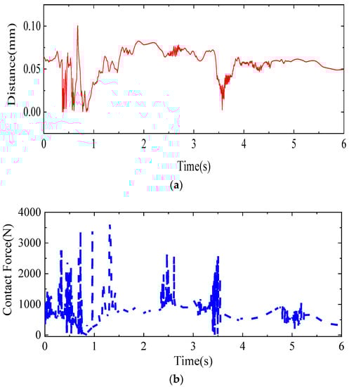
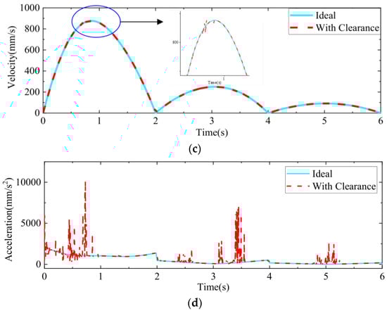
Figure 6.
Curve of motion parameters of the mechanism under the influence of clearance joints: (a) Clearance vector distance; (b) Variation curve of clearance contact force; (c) End speed curve; (d) End acceleration curve.

Table 1.
Stiffness coefficient and damping coefficient of joint.
Figure 6a shows the vector distance between the center of the pin and the center of the sleeve. At the beginning of the start-up phase, the pin collides violently with the sleeve due to gravity and driving torque, and the relative position between the two changes continuously in the three states of separation-contact-collision. The operation of the mechanism becomes smooth after a certain period of time, and the overall operation becomes smoother in the later stage. It can be seen that the operation fluctuates greatly at the beginning and the overall motion reliability is poor; continuous contact motion appears at the later stage. In order to ensure the accuracy of the mechanism movement and the service life of the mechanism, frequent starting and stopping of the machine should be avoided. Figure 6b shows the curve of contact force with time. During operation, a large contact force is generated at the gap, and from the overall effect, the contact force is the largest during the initial start-up phase, and the degree of collision gradually decreases at a later stage, causing the contact force to decrease as well. As shown in Figure 6c,d, there are large fluctuations in both velocity and acceleration at the start-up phase, with a maximum velocity of 832.2885 mm/s and a maximum acceleration of 10,218.89 mm/s2; both curves fluctuate slightly during the subsequent operation. The overall trend in both is consistent with the change in contact forces.
4.1.1. Effect of Clearance Size on the Dynamic Characteristics of Mechanisms with Clearance
In order to investigate the effect of clearance size on the end motion characteristics of the robot, this section sets the joint clearance sizes to be ideally no clearance, 0.1 mm, 0.2 mm and 1 mm respectively, while keeping other parameters constant. The results of the analysis are shown in Figure 7.
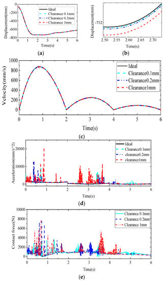
Figure 7.
Change curve of influence of clearance size on motion parameters of mechanism: (a) Displacement curve; (b) Partial enlargement of displacement curve; (c) End velocity variation curve; (d) End acceleration variation curve; (e) Joint contact force variation curve.
As shown in Figure 7a,b, the displacement trend of the end-marked points on the mechanical arm remains consistent at clearance sizes of 0.1 mm, 0.2 mm and 1 mm with the ideal case. The greater the clearance, the greater the deviation from the displacement curve, which means that the clearance affects the movement accuracy at the end of the mechanical arm. As can be seen in Figure 7c, the overall trend of the end velocity variation is consistent with the ideal state. From the overall perspective, the speed fluctuation reaches the maximum at the beginning of the start-up phase. The fluctuation caused by the joint gap is consistent with the period of contact collision between the joint components. As shown in Figure 7d, the end acceleration curve can be seen. The peak velocity fluctuation is tens or even hundreds of times the ideal state. The overall operating trend is consistent with the speed operating trend. The peak acceleration fluctuation occurs at the beginning of the start-up phase. For different joint gap sizes, the larger the joint gap of the robot, the larger the end acceleration fluctuation, which can make the robot’s motion less accurate. As shown in Figure 7e, the joint contact force variation curve is shown. The contact-collision-separation phenomenon occurs between the two components at the gap. The contact force between the joints fluctuates periodically. The velocity and acceleration fluctuations occur during the same time period as the velocity and acceleration amplitude fluctuations, which occur during the time period of contact-collision between the components. Comparing the joint collision forces under different gap sizes, it is found that the larger the gap size, the larger the gap collision force, and the more lagged the time of collision, the larger the gap. The larger the gap, the more difficult it is for the collision force to stabilize. Therefore, it can be seen that the larger the gap size is, the greater is the impact on the stability of the system.
4.1.2. Effect of Rotational Speed on the Dynamic Characteristics of Mechanisms with Clearance
During the movement, the overall operation of the robot containing clearance joints at different rotational speeds will change significantly. In order to quantitatively analyze the dynamic characteristics of the robot with clearance joints at different rotational speeds, the joint speed driving functions, as shown in Table 2, were set with the clearance size of 0.1 mm and other parameters were kept constant. The results are shown in Figure 8, Figure 9 and Figure 10.
Table 2.
Joint speed driving function.
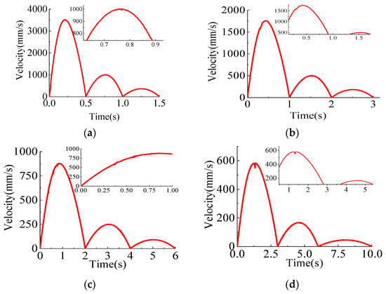
Figure 8.
Curve of end velocity change at different rotational speeds: (a) Velocity_1; (b) Velocity_2; (c) Velocity_3; (d) Velocity_4.
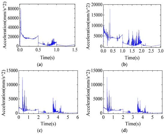
Figure 9.
Curve of end acceleration change at different rotational speeds: (a) Velocity_1; (b) Velocity_2; (c) Velocity_3; (d) Velocity_4.
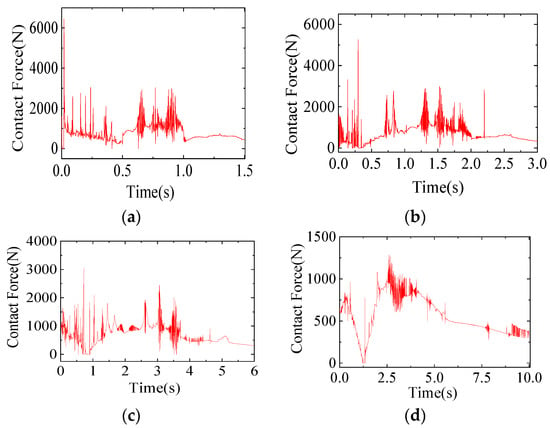
Figure 10.
The end contact force change curve of the joint with gap at different speeds: (a) Velocity_1; (b) Velocity_2; (c) Velocity_3; (d) Velocity_4.
Figure 8 shows the end velocity change curve at different rotational speeds. It can be seen that as the speed increases, the fluctuation of the velocity becomes larger and larger, and the fluctuation of the velocity is above and below the ideal value, and the velocity fluctuates drastically at the beginning of the start-up phase. The contact collision between the two components of the joint will also make a significant change in the speed of the contact due to the difference in speed; the greater the speed of the joint rotation, the more obvious the value of the end velocity change.
As shown in Figure 9, the end acceleration variation curves at different speeds; with the increase in speed, the peak variation of acceleration is also very large, even tens of times higher. At the beginning of the start-up phase, the acceleration changes dramatically, and during the subsequent operation, the end acceleration changes more and more dramatically, indicating that the joint with clearance produces more violent contact collisions under the increasing speed, which greatly reduces the stability of the system operation.
As shown in Figure 10, the contact force of the joint with clearance varies at different rotational speeds. The contact force and the variation amplitude between the shaft pin and the sleeve increase with the increase of the joint speed. The contact force between the pin and the sleeve increases as the speed of the joint increases. It can be seen that the change in frequency of contact force becomes larger with the increase of rotational speed at the same time. The greater the speed of the joint, the higher the frequency of contact collision of the joint with a gap, and the lower the reliability of the system operation.
From Figure 8 and Figure 9, it can be seen that the fluctuation of the end velocity increases with increasing speed but fluctuates around the ideal value. The peak change of acceleration is very large, and the change of end acceleration becomes more and more drastic during the subsequent runs, indicating that more violent contact collisions occur in the clearance joint with increasing speed, which coincides with the end contact force change in Figure 10. At the same time, the frequency of contact force change becomes larger with the increasing speed, which indicates that the faster the rotating speed, the higher the frequency of contact collisions in joints with clearance and the lower the reliability of the system operation.
4.1.3. Effect of Friction on the Dynamic Characteristics of Mechanisms with Clearance
The tangential relative slip velocity is generated in the relative motion of two components during operation, which results in the generation of tangential friction. In order to quantitatively analyze the dynamic characteristics of the robot with clearance joints at different friction coefficients, two sets of friction coefficients were selected. The friction coefficients for the first and second groups are Friction_1 = 0.3 and Fricton_2 = 0.5, respectively, while the clearance size of 0.1 mm and other parameters remain the same. The analysis results are shown in Figure 11, Figure 12 and Figure 13.
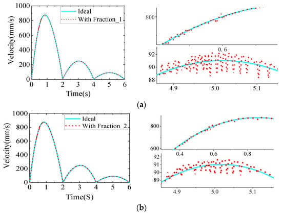
Figure 11.
The end velocity change curve when considering friction: (a) With Fraction_1; (b) With Fraction_2.
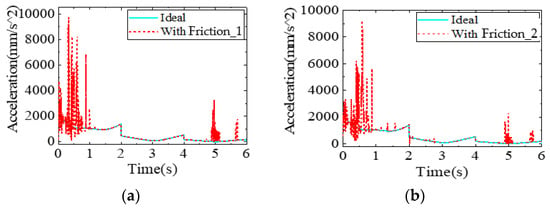
Figure 12.
The end acceleration change curve when considering friction. (a) With Fraction_1. (b) With Fraction_2.
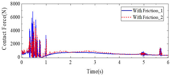
Figure 13.
Change curve of joint contact force when considering friction.
As shown in Figure 11, the end velocity variation curves for different friction states are shown. From the figure, it can be seen that when considering the friction, the fluctuation of the end speed curve of the robot has a significant delay compared with the time when there is no friction, and the speed change curve becomes symmetrical fluctuation near the ideal value; the fluctuation amplitude is small. The larger the friction coefficient, the weaker the fluctuation of speed, and the overall effect of friction on the end speed is smaller. As shown in Figure 12, the end velocity variation curves for different friction states are shown. From the figure, it can be seen that when considering the friction, the fluctuation of the end speed curve of the robot has a significant delay compared with the time when there is no friction, and the speed change curve becomes symmetrical fluctuation near the ideal value; the fluctuation amplitude is small. The larger the friction coefficient, the weaker the fluctuation of speed, and the overall effect of friction on the end speed is smaller. Figure 13 shows the change curves of joint contact force under different friction conditions. The fluctuation peak of the robot joint contact force curve decreases with the increase of friction coefficient, and the overall motion trend is consistent with the change of speed and acceleration, which indicates that the existence of friction will consume energy in the process of motion, reduce the contact force between the contacts, and then reduce the fluctuation of acceleration so that the motion reliability of the mechanism can be improved.
4.2. Wear Analysis of Clearance Joints
Rotating joints of mechanisms with clearance inevitably collide during operation. In the process of cyclic work, due to friction, impact forces in the material will produce a plastic deformation or material surface peeling and other phenomena, which directly change the shape and force characteristics of component working surfaces. In this analysis, we set the joint clearance to 0.1 mm, the speed to −180°/s; the run time is 0.5 s, the simulation step length is 1000 steps, and the wear coefficient is 6 × 10⁻¹⁴.
4.2.1. Wear Prediction for Rotating Joint with Clearance
This section analyses the wear of the swivel joint with clearance at different moments in the rotation. Figure 14 shows the sleeve wear depth curve of rotating joints with clearance for one run following the set conditions. It can be seen that the rotating joints with clearance wear non-uniformly, with intense shocks at the start-up phase, higher contact forces and larger initial wear.
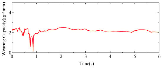
Figure 14.
Dynamic wear on the surface of the sleeve.
4.2.2. Rearrangement of Rotating Joint Sleeve with Clearance
Since the contact points and the slip intervals of the shaft pin on the sleeve surface are random, the wear process can be discretized into tiny intervals.; the contact forces, relative slip rates and wear rates in the discrete areas can thus be calculated. This section amplifies the wear by 103 times. From Figure 15a, it can be seen that the wear occurs with contact collisions as the shaft pin moves in the sleeve, and there is a separation-continuous contact process. Figure 15b shows that the curvature radius of the rearrangement after wear is not a constant value, which indicates that wear is more intense at the point where the contact and collision forces are higher.
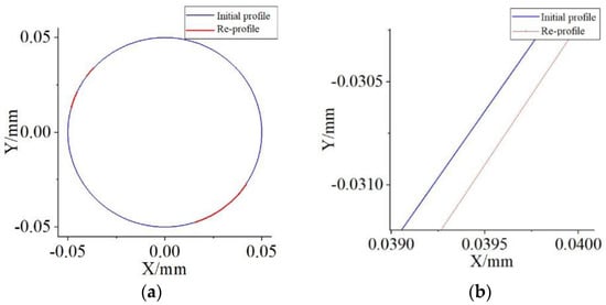
Figure 15.
Rearrangement of shaft sleeve after wear: (a) Rearrangement; (b) Partial magnification.
5. Conclusions
This paper establishes the mathematical models and analyzes the dynamic characteristics of a shield machine tool-changing robot with joint clearance. The effects of clearance size, rotational speed and friction coefficient on the dynamic characteristics of the clearance-containing mechanism were analyzed separately. With the increase of the clearance size, the fluctuation of velocity and acceleration increases, and the fluctuation frequency decreases, while the collision force at the clearance is difficult to stabilize. The faster the rotating speed, the more violent the end velocity and acceleration changes, and the more frequently contact collisions occur. The greater the friction coefficient, the weaker the fluctuations in speed and acceleration. With the effect of friction, the contact force between components and the fluctuations of acceleration will be reduced due to energy loss so that the kinematic reliability of the mechanism is improved.
The wear of the rotating joints with clearance is non-uniform, which is consistent with the contact collision between the shaft pin and sleeve. By rearranging the clearance of the worn sleeve surface and comparing it with that before wear, it is clear that there are different degrees of wear in different areas. Both theoretical and simulation analyses show that the method in this paper is feasible. The analysis method and analysis results in this paper can provide a reference for further motion error analysis and real-time motion error compensation. They can also be used as a basis for motion accuracy reliability analysis. The possible transient strong impact phenomenon in the joint motion and the influence of the motion trajectory of the tool changing action on the successful completion of the tool changing task need to be further investigated in the follow-up work.
Author Contributions
Conceptualization, W.Q. and L.W.; methodology, W.Q. and S.S.; formal analysis, S.S. and J.Z.; data curation, X.Y. and J.H.; writing—original draft preparation, W.Q. and S.S.; writing—review and editing, W.Q.; project administration, W.Q. All authors have read and agreed to the published version of the manuscript.
Funding
This work was partially supported by the National Natural Science Foundation of China (Grant No. 52175131), the National Science and Technology Major Project of the Ministry of Science and Technology of China (Grant No. J2019-IV-0002-0069, J2019-IV-0016-0084), the Applied Basic Research Programs of Liaoning Province of China (Grant No. 2022JH2/101300202) and the Natural Science Foundation of Liaoning Province of China (Grant No. 2021-MS-269).
Institutional Review Board Statement
Not applicable.
Informed Consent Statement
Not applicable.
Data Availability Statement
All the data used in this study can be found in the article.
Conflicts of Interest
The authors declare no conflict of interest.
References
- Xiang, W.; Yan, S. Dynamic analysis of space robot manipulator considering clearance joint and parameter uncertainty: Modeling, analysis and quantification. Acta Astronaut. 2020, 169, 158–169. [Google Scholar] [CrossRef]
- Liu, C.S.; Chen, B. The oblique impact dynamic study for a flexible beam undergoing large overall motion. Acta Mech. Sin. 2000, 32, 457–465. [Google Scholar]
- Masumi, O.; Takeda, Y. Design of target trajectories for the detection of joint clearances in parallel robot based on the actuation torque measurement. Mech. Mach. Theory 2021, 155, 104081. [Google Scholar]
- Cao, D.Q.; Chu, S.M.; Li, Z.F. Study on the non-smooth mechanical models and dynamics for space deployable mechanism. Chin. J. Theor. Mech. 2013, 45, 3–14. [Google Scholar]
- Chen, X.; Yang, W. Dynamic modeling and analysis of spatial parallel mechanism with revolute joints considering radial and axial clearances. Nonlinear Dyn. 2021, 106, 1929–1953. [Google Scholar] [CrossRef]
- Ting, K.L.; Hsu, K.L.; Yu, Z. Clearance-induced output position uncertainty of planar linkages with revolute and prismatic joints. Mech. Mach. Theory 2016, 111, 66–75. [Google Scholar] [CrossRef]
- Lara-Molina, F.A.; Dumur, D. A fuzzy approach for the kinematic reliability assessment of robotic manipulators. Robotica 2021, 39, 2095–2109. [Google Scholar] [CrossRef]
- Dubowsky, S.; Freudenstein, F. Dynamic analysis of mechanical systems with clearances, Part 1: Formulation of dynamic model. J. Eng. Ind. 1971, 93, 305–309. [Google Scholar] [CrossRef]
- Jiang, S.; Wang, T.; Xiao, L. Experiment research and dynamic behavior analysis of multi-link mechanism with wearing clearance joint. Nonlinear Dyn. 2022, 109, 1325–1340. [Google Scholar] [CrossRef]
- Birhanu, F.F.; Chen, Z.B.; Ma, W.S. Modeling and simulation satellite solar panel development and locking. Inf. Tech. J. 2010, 9, 600–604. [Google Scholar]
- Chen, S.; Cheng, G.; Pang, Y. Dynamic analysis and trajectory tracking control for a parallel manipulator with joint friction. Appl. Sci. 2022, 12, 6682. [Google Scholar] [CrossRef]
- Le Chau, N.; Dang, M.P.; Prakash, C.; Buddhi, D.; Dao, T.H. Structural optimization of a rotary joint by hybrid method of fem, neural-fuzzy and water cycle–moth flame algorithm for robotics and automation manufacturing. Robotics and Autonomous Systems. Robot. Auton. Syst. 2022, 156, 104199. [Google Scholar] [CrossRef]
- Yang, B.; Yang, W.; Zhang, G.; Ran, Y. Precision analysis of series-parallel machine tool based on hierarchy motion function units. Mech. Mach. Theory 2022, 172, 104834. [Google Scholar] [CrossRef]
- Earles, S.W.E.; Wu, C.L.S. Motion analysis of a rigid-link mechanism with clearance at a bearing using Lagrangian mechanism and digital computation. Mechanisms 1973, 1, 83–89. [Google Scholar]
- Flores, P.; Lankarani, H.M. Dynamic response of multibody systems with multiple clearance joints. J. Comput. Nonlin. Dyn. 2011, 7, 636–647. [Google Scholar]
- Muvengei, M.; Kihiu, J.; Ikua, B. Effects of clearance size on the dynamic response of planar multi-body systems with differently located frictionless revolute clearance joints. J. Energ. Tech. Policy 2012, 2, 7–19. [Google Scholar]
- Varedi, S.M.; Danili, H.M.; Dardel, M. Optimal dynamic design of a planar slider-crank mechanism with a joint clearance. Mech. Mach. Theory 2015, 86, 191–200. [Google Scholar] [CrossRef]
- Shi, B.; Jin, Y. Dynamic simulation and modeling of revolute clearance joint for virtual prototyping. J. Mech. Eng. 2009, 45, 299–303. [Google Scholar] [CrossRef]
- Zhao, Y.; Bai, Z.F.; Wang, X.G. Dynamics analysis of two-axis-position mechanism of satellite antennas with joint clearance. J. Astronaut. 2010, 31, 1533–1539. [Google Scholar]
- Efremenkov, E.A.; Martyushev, N.V.; Skeeba, V.Y.; Grechneva, M.V.; Olisov, A.V.; Ens, A.D. Research on the possibility of lowering the manufacturing accuracy of cycloid transmission wheels with intermediate rolling elements and a free cage. Appl. Sci. 2022, 12, 5. [Google Scholar] [CrossRef]
- Hao, X.Q.; Chen, J.Y. Effects of different materials in joints on dynamic characteristics of a mechanism with clearance. J. Vib. Shock. 2012, 31, 19–21. [Google Scholar]
- Xu, L.X.; Yang, Y.H.; Li, Y.G. Modeling and analysis of planar multibody systems containing deep groove ball bearing with clearance. Mech. Mach. Theory 2002, 56, 69–88. [Google Scholar] [CrossRef]
- Fateh, M.M.; Khorashadizadeh, S. Robust control of electrically driven robots by adaptive fuzzy estimation of uncertainty. Nonlinear Dyn. 2012, 69, 1465–1477. [Google Scholar] [CrossRef]
- Yuan, X.; Meng, Q.; Xie, F.; Liu, X.-J.; Wang, J. Position error modeling and accuracy evaluation of n-dof translational parallel manipulators that can be transformed into n four-bar mechanisms based on motion/force transmissibility. Mech. Mach. Theory 2022, 176, 105012. [Google Scholar] [CrossRef]
- Pereira, M.S.; Nikravesh, P. Impact dynamics of multibody systems with frictional contact using joint coordinates and canonical equations of motion. Nonlinear Dyn. 1996, 9, 53–71. [Google Scholar] [CrossRef]
- Guo, A.; Batzer, S. Substructures analysis of a flexible system contact-impact event. Trans. ASME 2004, 126, 126–131. [Google Scholar] [CrossRef]
- Yu, L.X.; Liu, C.S. Dynamic simulation and kinetic description of revolute joint with spatial clearance. Acta Scicentiarum Nat. Univ. Pekinesis. 2005, 41, 679–686. [Google Scholar]
- Zhao, Y.; Bai, Z.F. Dynamics analysis of space robot manipulator with joint clearance. Acta Astronaut. 2011, 68, 1147–1155. [Google Scholar] [CrossRef]
- Su, Y.W.; Chen, W.; Zhu, A. Numerical analysis of wear coupling with dynamics behavior of machine. Tribology 2009, 29, 50–54. [Google Scholar]
- Zhao, Q.; Guo, J.; Hong, J. Time-dependent system kinematic reliability analysis for planar parallel manipulators. Mech. Mach. Theory 2020, 152, 103939. [Google Scholar] [CrossRef]
- Zhang, Y.J.; Zhao, N.; Lu, J. Finite element modal analysis of reciprocating compressor crankshaft based on Ansys workbench. Appl. Mech. Mater. 2014, 488–489, 1208–1210. [Google Scholar] [CrossRef]
- Freidovich, L.; Robertsson, A. Lugre-model-based friction compensation. IEEE T. Contr. Syst. T. 2010, 18, 194–200. [Google Scholar] [CrossRef]
- Liu, L.L.; Liu, H.Z.; Wu, Z.Y. Research progress of friction model in mechanical system. Adv. Mech. 2008, 38, 201–213. [Google Scholar]
- Zhou, Z.; Zheng, X.; Wang, Q.; Chen, Z.; Sun, Y.; Liang, B. Modeling and simulation of point contact multibody system dynamics based on the 2d Lugre friction model. Mech. Mach. Theory 2021, 158, 104244. [Google Scholar] [CrossRef]
- Popov, V.L. Generalized archard law of wear based on rabinowicz criterion of wear particle formation. Facta Univ. Ser. Mech. Eng. 2019, 17, 39–45. [Google Scholar] [CrossRef]
- Hanief, M.; Charoo, M.S. Archard’s wear law revisited to measure accurate wear coefficient considering actual sliding velocity. Mater. Today Proc. 2021, 47, 5598–5600. [Google Scholar] [CrossRef]
- Lankarani, H.M.; Nikravesh, P.E. A contact force model with hysteresis damping for impact analysis of multibody systems. J. Mech. Design 1990, 112, 369–376. [Google Scholar] [CrossRef]
- Zhang, J.; Fang, M.Y.; Zhao, L.; Zhao, Q.L.; Liang, X.; He, G.P. A continuous contact force model for the impact analysis of hard and soft materials. Mech. Mach. Theor. 2022, 177, 105065. [Google Scholar] [CrossRef]
- Flores, P.; Ambrósio, J.; Claro, J.C.P.; Lankarani, H.M.; Koshy, C.S. A study on dynamics of mechanical systems including joints with clearance and lubrication. Mech. Mach. Theor. 2006, 41, 247–261. [Google Scholar] [CrossRef]
- Li, Y.Y.; Yang, Y.; Li, M.; Liu, Y.F.; Huang, Y.F. Dynamics analysis and wear prediction of rigid-flexible coupling deployable solar array system with clearance joints considering solid lubrication. Mech. Syst. Signal. Proc. 2022, 162, 108059. [Google Scholar] [CrossRef]
- Lai, X.; He, H.; Lai, Q.; Wang, C.; Yang, J.; Zhang, Y.; Fang, H.; Liao, S. Computational Prediction and Experimental Validation of Revolute Joint Clearance Wear in the Low-velocity Planar Mechanism. Mech. Syst. Signal Process. 2017, 85, 963–976. [Google Scholar] [CrossRef]
- Archard, J.F. Contact and Rubbing of Flat Surfaces. J. Appl. Phys. 1953, 24, 981–988. [Google Scholar] [CrossRef]
- Aghababaei, R.; Zhao, K. Micromechanics of material detachment during adhesive wear: A numerical assessment of Archard’s wear model. Wear 2021, 476, 203739. [Google Scholar] [CrossRef]


Publisher’s Note: MDPI stays neutral with regard to jurisdictional claims in published maps and institutional affiliations. |
© 2022 by the authors. Licensee MDPI, Basel, Switzerland. This article is an open access article distributed under the terms and conditions of the Creative Commons Attribution (CC BY) license (https://creativecommons.org/licenses/by/4.0/).