Abstract
Near space has attracted major countries’ attention due to the fact that it is a new cognitive space of Earth and acts as an important national security space. Near-space solar-powered unmanned aerial vehicles (UAVs) are becoming a focus of research in the aviation field. However, it is difficult for solar-powered UAVs to climb such high heights and achieving optimal cruising levels is challenging. A balloon-borne-based aircraft that rises with the help of a balloon avoids difficult climbing processes and initiates a new research direction in the near-space aviation domain. Simultaneously, the special mode of taking off poses a great challenge for the pull-up control of balloon-borne aircraft, especially for large wingspan aircraft. In this paper, we propose an adaptive launch control for the pull-up process of large-scale balloon-borne-based aircraft. First, the flight control of the pull-up process for a large-scale balloon-borne-based aircraft is analyzed. Then, a flight dynamic model considering elastic deformation is established. Finally, an adaptive aircraft pull-up control algorithm is proposed. We evaluate it by performing simulation experiments and comparing it with the latest control algorithm utilized in physical experiments. The experiment’s results demonstrate the effectiveness of the proposed algorithm with respect to overcoming challenges in controlling pull-up processes and its superiority compared to the latest control algorithm.
1. Introduction
Near space (i.e., the space measured at 20∼100 km from the ground) has characteristics of low atmospheric density, no clouds or rain, and strong solar radiation [1], and it is very suitable for the flight of solar-powered unmanned aerial vehicles (UAVs). This characteristic permits great value in using near space for military or other applications. Due to near space’s significant value, near-space vehicles are becoming a focus of research. Solar-powered UAVs, as a mainstream direction, have been researched at home and abroad. They firstly take off from land, climb up with high-power output, and finally cruise during the day and night, undertaking more and more tasks such as monitoring tasks or other relay-forwarding tasks. This makes solar-powered UAV more promising.
Recently, solar-powered UAVs with large wingspans attracted increasing research studies. A major reason for this structural design is that large wingspans increase the lift–drag ratio. It is easier to climb up for UAVs when their lift–drag ratio increases even with the same wing area. The increase in the lift–drag ratio enables a decrease in take-off cost as taking off and cruising at the corresponding altitude are expensive processes. However, there are other limitations when increasing the lift–drag ratio with a large wingspan. On the one hand, the wing root’s load and structural complexity increase with the continuous increase in wingspan, which further leads to the growing weight proportion of the structure. On the other hand, the climb state needs to be considered in the design of the aircraft. It is hard to make the most optimal cruise point as the only design point.
In order to solve the above problems faced by UAVs with large wingspans, based on relevant research studies [2,3], we proposed and implemented the scheme of launching large wingspan UAVs with balloons in near space for the first time in China. The process can be simply described as follows. First, a high-altitude balloon rises to a certain altitude. Second, it is launched and cruises in the air. Finally, it lands via a runway. The balloon-based large-wingspan UAV can quickly rise to the height of adjacent spaces and reduce the impact of strong winds and jet-stream areas. This avoids the risk of overheating with respect to the UAV’s motor caused by high-power continuous outputs in the climbing stage and also solves the problem of the limited payload weight caused by the increase in the weight proportion of the entire machine’s structure due to the large wingspan. In addition, the balloon-based large wingspan UAV can use near-space cruise flights as the only optimal design reference, which improves the aerodynamic efficiency of the aircraft and the propeller.
Even though the increase in height with the balloon does notinvolve the complex states of the UAV in the climbing-up process and can beneficially arrive at a certain altitude, the characteristic of having a large wingspan poses a new challenge for launch processes. When UAVs with large wingspan are released, their flight process after being launched is accompanied by drastic changes in airspeed, attitudes, and attack angles. Drastic changes lead to a large elastic deformation in aircraft with large wingspan and introduce an important impact on flight control and flight safety. Hence, the control model is more complex due to the large elastic deformation compared to having a common wingspan. An inaccurate control model may lead to failures during launching. In addition, at the initial time of launching, the speed of the aircraft is zero or it moves upward with the high-altitude balloon with a small increase in speed. Thus, obtaining suitable airspeeds and attack angles that can maintain a UAV’s cruise flight is another challenge.
Currently, launch tests of aircraft are mainly carried out for small-sized rigid aircraft, and there is little study on launching aircraft with large wingspans and elasticity. To address the above challenges, by carefully analyzing the launching process of UAVs with large wingspans, we observed that it is similar to the launch and control of small unpowered parachute gliders. For example, the “parachute-dive-horizontal flight” process of small unpowered parachute gliders takes parachute cut-off times as the start time of the automatic control and defined the working process as four initial states: parachute release, wing deployment, initial horizontal flight, and cruise flight [4]. After the parachute glider falls vertically, the pull-up control is applied to change its trajectory into horizontal flight [4,5].
Based on these observations and the analysis, our key idea is to build a complex control model based on UAVs with large wingspans and to apply the launching strategy of an unpowered parachute glider to balloon-borne-based UAVs with large wingspans. To this end, in this paper, we designed an improved adaptive controller for UAVs with large wingspans to tackle challenges that exist in the launch flight test of balloon-borne-based solar-powered UAVs. More specifically, first, we analyze the flight control of the pull-up process for the large-scale balloon-borne-based aircraft. Then, we establish a flight dynamic model considering elastic deformation. This helps the design of the launching controller. Finally, we propose an adaptive aircraft pull-up control algorithm and design an improved adaptive controller dedicated for the launch control of balloon-borne-based solar-powered UAVs. We perform a simulation test to evaluate the effectiveness of the proposed algorithm and a physical test to assess the pull-up control design for balloon-borne-based aircraft with large wingspan.
To conclude, the main contributions can be summarized as follows:
- This paper propose an adaptive control model to tackle the pull-up control of balloon-borne-based solar-powered UAVs with large wingspans, which is a tough problem faced by these UAVs.
- This paper introduces a series of factors that influence the elastic deformation of fuselages in solar-powered UAVs to approximate their real-world flight dynamic model and proposes a stage-based pull-up control strategy.
- This paper verifies the effectiveness of the adaptive control model on pull-up processes with the simulation experiment and demonstrates its superiority over the latest control model utilized in physical experiments.
The rest of the paper is organized as follows. Section 2 illustrates background information on solar-powered UAVs and related studies. Section 3 analyzes important factors in pull-up control processes. In Section 4, a flight dynamic model of balloon-borne unmanned aerial vehicles considering elastic deformations and the influence of a low Reynolds number is established. Section 5 presents the UAV launch and pull-up control algorithm. Section 6 evaluates the proposed control algorithm by conduciting a simulation experiment and comparison. In Section 7, we discuss limitations and future work. Finally, the conclusion is presented in Section 8.
2. Background and Related Work
In this section, we mainly introduce background information about solar-powered UAVs and related studies.
2.1. Background
Solar-powered UAVs usually fly at the height of near space and can take full advantages of near-space’s flight condition. They have already been researched for various applications, such as monitoring tasks or relay-forwarding tasks. Since the appearance of “sunrise-1” solar-powered UAV in November 1974, many countries carried out studies on solar-powered UAVs [6,7,8]. Moreover, using large wingspans is becoming an important development direction of solar-powered UAVs due to the fact that the lift–drag ratio of aircraft increases with the increase in wing aspect ratios. For example, the “Odysseus” solar-powered UAV has a wingspan of 74 m, and the “Eagle” solar-powered UAV has a wingspan of 121.9 m. However, the large wingspan also creates other problems, such as an increase in structural complexity and the weight proportion of the structure. These problems could be tackled effectively by removing a small amount of the wingspan and by combining wingtips in the air for combined flight applications and separating the wingtips before landing.
Currently, the take-off processes of solar-powered UAVs are either from runways or balloon-borne processes [6]. The mode of taking off from a runway is usually applied to UAVs with large or small wingspans. These solar-powered UAVs need to cross strong winds in jet-stream areas during the climbing phase, which impacts flight safety. The other taking-off mode uses balloon-borne processes, which is widely used in the aircraft field. Many high-altitude balloon-launching tests are reported at home and abroad [9,10,11,12,13,14,15,16,17], as shown in the Table 1.

Table 1.
Launch tests of balloon-borne UAVs in the world.
The specific taking-off process of balloon-borne-based UAVs consists of four phases, including carrying high-altitude balloons, launching, cruising in the air, and landing via a runway, as shown in Figure 1. Such forms of taking-off modes have already been successfully applied to UAVs with wingspans that are quite small, and data show that 1090 balloon-borne launch tests in the stratosphere have been conducted since 2015 [18]. For UAVs with large wingspans, performing pull-up control processes is difficult and challenging.
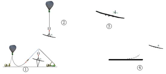
Figure 1.
The launch and flight process diagram of balloon-borne UAVs. The four phases are as follows: high-altitude balloon carrying, launching, cruising in the air, and landing via a runway.
2.2. Related Work
Unpowered Parachute Glider: Studies that are most related to ours include those on small unpowered parachute gliders [4,5]. For instance, [4] analyses the “parachute-dive-horizontal flight” process of small unpowered parachute gliders and takes the parachute cut-off time as the start time of the automatic control. Our work uses near-space cruise flights as the only optimal design reference. The authors in [5] studies the attitude estimation and fusion algorithm of small unpowered parachute gliders from vertical launch to horizontal flight.
Even though our study has similarities with the studies mentioned above, there are differences that can be summarized in terms of two aspects. First, the solar-powered UAV is a light and flexible large wingspan aircraft; however, small unpowered parachute gliders are small in size and have high rigidity. Second, the motion of solar-powered UAV is completely different from launching small-sized and high-rigidity aircraft. For example, the former has high requirements on the overload limit of the release due to the limited strength of the structure, so it has high requirements on the pull-up time and pull-up speed. In addition, it also needs to consider the impact of elastic deformation on the structure and control. On the other hand, the latter does not need to consider the problem of structural strength limitations or the influence of stiffness on flight controls. We mainly focus on researching the launch of flexible aircraft with large wingspans.
Aircraft with large wingspans: The authors of [19] considered the effect of nonlinear geometries and proposed a nonlinear trim and flight load analysis method for large flexible aircraft based on the CR (Co Radical) theory. The authors pointed out that when elastic deformation occurs in a flexible wing aircraft with large wingspan, the attack angle of the local wing section increases, resulting in the problem of dynamic stall [20]. Studies established a structure/flight coupling dynamic model that can reflect the flexibility characteristics of solar-powered UAV by using the Lagrange equation, analyzed the longitudinal stability of UAVs using the Root Locus Method, and finally studied the impact of elastic deformations on longitudinal flight control [21]. However, these works only focus on the stability analysis and control of UAVs when elastic deformation occurs. On the contrary, our work focuses on the control a different process (launching and pull-up process) for aircraft with large wingspans.
Launch and pull-up control: The authors of [3] adopt different control methods based on the flight characteristics of different stages of a model-free flight test, which well solves the problems and provides a safe separation between the model aircraft and carrier aircraft and provides the contorl of horizontal flight at high attack angles. The authors of [22] established a dynamic model by considering elastic deformation, analyzed the static stability, and carried out controller designs and launch experiments for scaling UAVs . The authors of [23] analyzed the constraints that UAVs should meet during the launching process and optimized the command of the pitch angle by using the control variable parameterization method. Although these efforts focus on launching and pulling processes, they do not involve the launch of aircraft with large wingspans. The launch of aircraft with large wingspans is more challenging.
3. Flight Control Analysis of Pull-Up Process
In this section, we introduce two influencing factors, including a low Reynolds number and elastic deformations on a UAV’s flight control in its pull-up process.
3.1. Low Reynolds Number
High-altitude balloons and solar-powered UAVs have obvious low Reynolds number characteristics in near-space areas. There are many special flow phenomena [24,25,26,27,28,29]. For asymmetric airfoils such as wings, its aerodynamic efficiency drops sharply and the lift–drag ratio decreases with a decrease in Reynolds number. When the Reynolds number decreases to , the lift–drag ratio is only 10% of the conventional Reynolds number [30]. These features affect the lift and drag of the aircraft, its propeller efficiency, and its control surface efficiency. For symmetrical airfoils such as tje horizontal stabilizer and the vertical fin, there is a small platform or even “s” bending near small attack angles, and the platform will gradually be eased and disappear with an increase in the Reynolds number [31]. The reasons for these two special phenomena are related to the triggering and evolution mechanism of laminar-induced separation that are formulated during its bubble variation with the Reynolds number and attack angle.
3.2. Elastic Deformation
Apart from the low Reynolds number, elastic deformations are influencing factors on the pull-up process. The fuselages of large-scale aircraft utilize carbon-fiber composites when they are manufactured. Hence, the fuselage has obvious elastic deformations and aeroelastic effects due to the special material and its large scale. Such characteristics have negative impacts on the pull-up process. For instance, the authors in [19] proposed a nonlinear trim and flight load analysis method based on the structural dynamic model of large flexible aircraft established by the CR(co rotation) theory and by considering geometric nonlinear effects. Another work pointed out that when the flexible aircraft with a high aspect ratio had elastic deformations or wing torsion, the attack angle of local wing profile increases, thus resulting in flow separation and the occurence of dynamic stall [20].
Based on aircraft aerodynamic data combined with numerical simulations, ground ballooning tests, and flight test data, our previous work involved an in-depth study on the longitudinal control of solar-powered UAVs by considering the elastic deformation of fuselages [22]. First, the aerodynamic force on the horizontal stabilizer is obtained by comparing the elastic deformation of the fuselage in ballooning tests and static load tests; thenm, static loading tests were carried out. Then, the pitch moment coefficient distribution of the aircraft considering the elastic deformation of the fuselage is obtained by calculating the longitudinal moment balance of the entire aircraft. The influence of flight speeds on the pitch moment coefficient provided by the horizontal stabilizer and the influence of flight speeds and elevator deflection angles on the control surface effect are analyzed. Finally, a complete dynamic model including an elastic structural dynamic model is established; the pitch angle(theta) and the value of elevator control surface (de) are compared with the rigid model, as shown in Figure 2 and Figure 3, respectively.
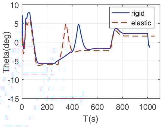
Figure 2.
The comparison of pitch angles between rigid and elastic models.
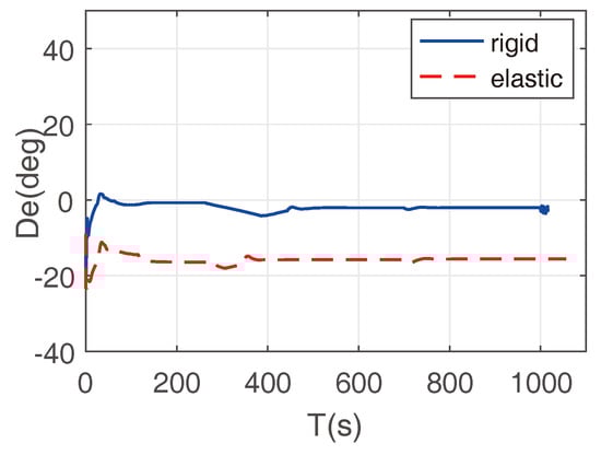
Figure 3.
The value comparison of the elevator control surface between rigid and elastic models.
It can be seen from Figure 2 that the aircraft’s pitch angle decreases by about 0.5. Figure 3 shows that the elastic deformation of the aircraft fuselage and horizontal stabilizer leads to an increase in the trim elevator angle by 13.5. The effect of elastic deformations will seriously weaken the efficiency of the elevator control surface, and considering the effect of elastic deformations on the aircraft’s longitudinal alignment and compensating the horizontal stabilizer angle are necessary.
4. Dynamic Model of Balloon-Borne UAVs
This section illustrates the dynamic model of balloon-borne UAVs. The longitudinal motion equation of the large wingspan UAV can be written as follows:
where and are the state matrix and control matrix, respectively. V is the velocity, is the attack angle, is pitch rate, and q is pitch angle. The matrix of A and B can be described as follows:
where , , , , , , , , , , , , , and . They are all dependent derivative formulas. In the above equations, m indicates mass. is the moment of inertia. , , and denote the lift coefficient, drag coefficient, and pitching moment coefficient. Q represents the dynamic pressure, and S is the longitudinal reference area. c stands for the longitudinal reference length. , , and g illustrate the elevator control input, engine control input, and gravitational acceleration, respectively.
Once these equations are obtained, calculating the forces and moments that act on the UAV is necessary. The total aerodynamic force acting on the aircraft includes , which is generated by the wing, the aerodynamic force acting on the fuselage, , and aerodynamic forces on the horizontal stabilizer, . In addition, gravity affects the aircraft (). Each force is illustrated in Figure 4.
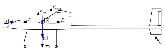
Figure 4.
The reference frame and each force on the aircraft.
4.1. Longitudinal Static Stability
Figure 5 shows the longitudinal static stability of the aircraft with the attack angle, and it is the ratio of the distance between the center of mass and the aerodynamic focus relative to the average aerodynamic chord length. The aircraft is stable when it has negative static stability. The longitudinal stability is 8.16% when the attack angle is 2 degrees, which is the minimum. In other attack angles, the static stability is more than 13%. The UAV is longitudinally stable and can meet the requirements needed during launch and flight processes.
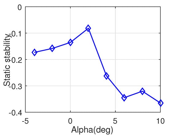
Figure 5.
The longitudinal static stability of the launched aircraft.
4.2. Dynamic Stability
The weight of the aircraft used is 90.0 kg and the wing area is 14.5 m. Combined with the aircraft aerodynamic data in and m, matrices A and B in Equation (1) are calculated, as shown in Equations (2) and (3). Following matrix A and B, the corresponding characteristic roots of Equation (1) are shown in Table 2. We can see that there are two pairs of complex roots, including and . The first pair, , corresponds to short-term motions, which includes the oscillation mode in the short-term and fast attenuation. The damping ratio is 0.7916 and the natural frequency is 4.58. The second pair, , corresponds to the phugoid mode with slow attenuation. The damping ratio is 0.1058, and the natural frequency is 0.3828. Overall, the system is dynamically stable.
Table 2.
The calculated longitudinal characteristic roots in Equation (1).
4.3. Modal and Flutter Analysis
In order to calculate the mode of the aircraft, it is assumed that the aircraft is in a free-flight state. Using MSC NASTRAN software for model analyses, natural frequency results are shown in Figure 6. Here, mode 2 represents the wing’s vertical first-order bending, and mode 5 represents the load compartment’s first-order bending. Mode 10 represents the horizontal stabilizer’s first-order reversal, and mode 12 represents first-order bending in the vertical fin.
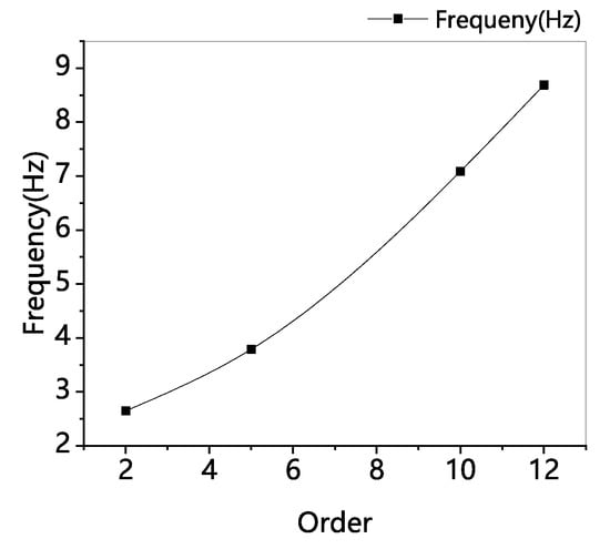
Figure 6.
Natural frequency of the aircraft’s fuselage at each order.
In addition, unsteady aerodynamic calculations also need to be considered. To this end, the doublet-lattice method is adopted. The atmospheric density is 1.225 kg/m at sea-level, and the reference Mach number is 0.1. The unmatched flutter is used, and the results are shown in Figure 7. The results show that the flutter velocity is 35.2 m/s, and the flutter frequency is 6.69 Hz at sea level. The cruise velocity is much lower than the flutter velocity, and the control frequency is much lower than the flutter frequency. The flutter analysis of 4 km and 10 km is similar to the sea level. This shows that the influence of flutter cannot be considered in the aircraft’s design.
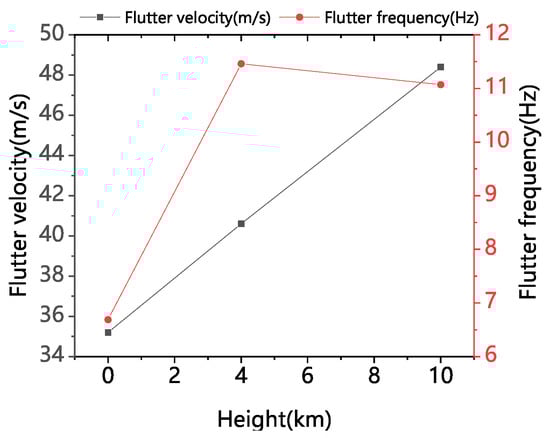
Figure 7.
Flutter velocity and flutter frequency at different heights.
5. Pull up Control Design for Balloon Launch Large-Scale Aircraft
We utilize an adaptive control for the pull-up process. The “adaptive control” is shown with respect to two aspects. First, according to the characteristics of launch stages and our accumulation of control algorithms [32,33], different control strategies are carried out on three channels of the UAV. Second, the pitching angle changes with the pull-up process of the aircraft, and considering such changes is indispensable.
5.1. Adaptive Control Strategy
Based on the characteristics of the launch and pull-up process, we divide the control process into four stages. The corresponding control flow chart is shown in Figure 8. Concretely, Phase 1 involves pitch angle tracking controls. The aircraft rotates around the celestial axis before launching, which leads to uncertainties in heading and horizontal motions. Therefore, in this phase, the longitudinal channel executes pitch angle tracking controls, leaving the roll and heading uncontrolled. Phase 2 involves heading stability-augmentation control. In this phase, the aircraft is pulled up according to the pitch-angle command, and the aircraft’s heading is definite. The heading stability-augmentation control is utilized to control the roll angle of the aircraft at 0 degrees. Phase 3 involves the fixed pitch angle directional glide control. As the engine increases its output continuously, the required airspeed is provided by gliding at a fixed angle in order to ensure that the flight speed of the aircraft is within the safety envelope. At this moment, the aircraft flies with a fixed heading and a fixed glide angle and controls the roll angle at 0 degreea. Phase 4 involves cruise flight controls. The UAV shifts to the cruise flight mode; i.e., the first three channels track and control the UAV according to control commands. The pull-up process is completed.
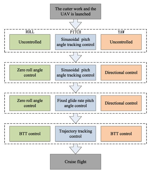
Figure 8.
Four stages’ control strategy on the pull-up process.
The PID control is adopted for longitudinal control and lateral directional control [34]. The structure diagram of thepitch controller is shown in Figure 9. The pitch angle’s error, , is calculated by subtracting the pitch angle from the pitch command . Control input is finally obtained via the proportional integral of the pitch error and the damping feedback by the pitch rate, q. For roll control, it is consistent with pitch control. The structure diagram of yaw control is shown in Figure 10. The difference in yaw control is based on the proportional integral of the yaw angle’s error, , and the yaw rate’s feedback, r. The feedback of roll rate p and roll angle increased to reduce the sideslip angle. Since the dynamic pressure changes rapidly and greatly during the pull-up process, the proportional coefficient, integral coefficient, and differential coefficient automatically adapt to the dynamic pressure. These coefficients are mathematically described as follows:
where , , and are control inputs of the elevator control surface, aileron control surface, and rudder control surface, respectively. , , and are proportional coefficients of the roll error, pitch error, and yaw error, respectively. , , and are integral coefficients of the roll error, pitch error, and yaw error, respectively. , , and are differential coefficients of the roll rate, pitch rate, and yaw rate, respectively. and are coordination control coefficients.
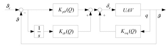
Figure 9.
Structure diagram of the pitch controller.
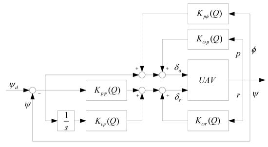
Figure 10.
Structure diagram of the yaw controller.
5.2. Improved Algorithm Design
In addition to the design of the pull-up control strategy, the launch control strategy should also be considered in the controller’s design. The balloon-based UAV utilizes pitch angle tracking controls based on two considerations. First, the pitch rate is 0 degrees per second at the initial and final moment. Second, pitching movements provided by the elevator control surface is small due to the low airspeed at the initial time. The corresponding sinusoidal pitching angle is shown in Equation (7):
in which is the initial pitch angle, and is the time constant related to the pull-up speed, which is decided by the response time of aircraft model in the desired launch height. k is a constant. Judgment conditions of the completion of the pull-up process are as follows: (1) The time is greater than the pull-up time constant; (2) the preset pull-up completion time is not reached, but the pull-up has been completed; (3) cruise flight is entered via manual controls. After the UAV is pulled up, it enters the cruise flight mode. The pitch command of pull-up control processes is shown in Figure 11.
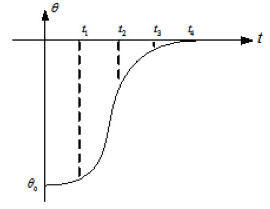
Figure 11.
Pitch command of the pull-up control; stands for the initial pitch angle.
6. Evaluation
We evaluate the proposed launch and pull-up control strategy with a simulation experiment. This section first illustrates the experimental setup and then illustrate the results on evaluating the proposed algorithm.
6.1. Experimental Setup
Experiment Settings. We first provide the experiment’s settings. For the simulation test, the simulation conditions are as follows: the height is 20,000 m and velocity is m/s. Considering the acceleration of the aircraft and the safety of the process, the initial pitch angle is −76 deg, and the rotation angle’s rate is 3 deg/s.
Apart from the experiment’s settings, the rotation angle rate of the UAV tied with the balloon affects the roll rate and yaw rate under the body’s coordinate frame. In addition, the increase in speed under the initial coordinate will further affect the speed components of the x-axis, y-axis, and z-axis under the body’s coordinate frame. Thus, we provide two coordinate transformations.
Rotation speed of the platform. Considering the influence of the rotation of the balloon’s platform at the initial time, the following conversion relationship can be obtained by transforming the rotation angle’s rate under the inertial system into the body’s axis system.
where is the roll rate, pitch rate, and yaw rate in the body coordinate, is the pitch angle, roll angle, and yaw angle.
Platform rising speed. The coordinate conversion matrix from the initial coordinate to the body’s coordinate is described as follows:
where is the speed with respect to the body’s coordinate, and is the speed with respect to the initial coordinate.
Baselines. In order to evaluate the effectiveness of our proposed strategy, we compare the simulation experiment to the control algorithm utilized in the latest physical experiment [22]. The settings of physical experiment are as follows: The aim height is 2000 m, and the pull-up control algorithm utilizes the exponential pitch-angle-based model.
Metrics. We utilize the maximum deviation as the evaluation basis, which is . We do not use the steady-state’s time that the control system spend becoming steady mainly because the aircraft has flexible structures. When stability is attained quickly, the aircraft may fracture more easily.
6.2. Experiment Results
The results of simulation experiment when using the proposed algorithm are shown in Figure 12, Figure 13, Figure 14, Figure 15 and Figure 16. Figure 12 describes the tracking of the pitch angle’s command. Overall, we can see that two curves indicating the pitch command and the pitch angle fit well. Concretely, at the initial time, the elevator control surface’s efficiency is low due to its low airspeed, and then it increases until at eighth second. After the 8th second, the aircraft has negative angular rate movements until pulls up at about 13th second. These results demonstrates that the control strategy can track the pitch command well and realize the pull-up of the UAV.
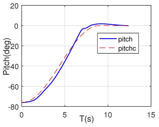
Figure 12.
Pitch angle command tracking in the pull-up process.
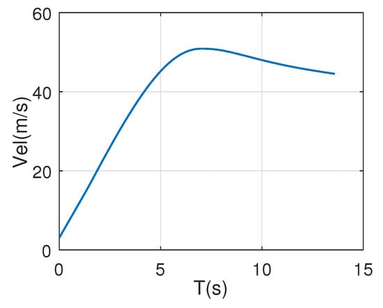
Figure 13.
Airspeed in the pull-up process.
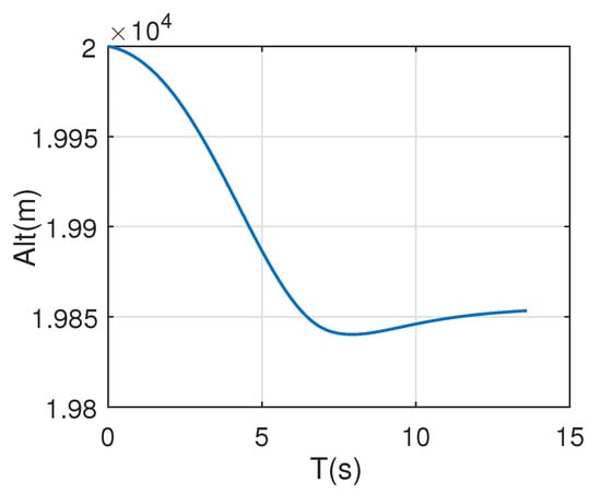
Figure 14.
Altitude in the pull-up process.
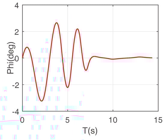
Figure 15.
Roll angle in the pull-up process.
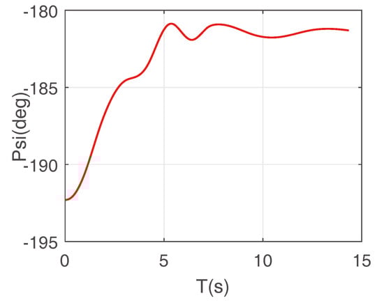
Figure 16.
Yaw angle in the pull-up process.
Figure 13 and Figure 14 provide changes in the airspeed and altitude during the pull-up process. The initial vertical velocity is 3 m/s and its direction is upward; then, its velocity sharply increases from −3 m/s under the action of gravity, and the maximum true airspeed of the aircraft is 49.42 m/s. The altitude drops by 147.3 m during the launching process.
Figure 15 and Figure 16 represent the response of the roll angle and yaw angle. For the initial rotation speed of 3 degree per second of the aircraft and the balloon, there is an initial roll rate and an yaw rate after launch. The roll angle changes between −3.23 deg and 2.66 deg, the yaw angle changes from −192.3 deg to −180.2 deg, and both of them gradually stabilize after 8 s.
In addition, we also provide results from the comparison of the simulation experiment when using the latest control algorithm in the pull-up process for UAVs with large wingspans, as shown in Figure 17. Here, the blue dotted line is the result of the proposed control algorithm, and the blue solid line represents the algorithm used in the latest implementation. We can see that the of the pitch angle when using the proposed control algorithm is smaller than that of the latest algorithm. This demonstrates that the proposed pull-up control algorithm is better than the state-of-the-art pull-up control algorithm. We still record changes in the pitch angle when performing flight tests with the latest algorithm, as shown in Figure 18 and Figure 19. Here, Figure 18 represents the rising process of the balloon-borne solar-powered UAV, and Figure 19 illustrates the pitch angle and pitch angle command. From Figure 19, we can see that the UAV was launched at the time of 217.3 s, and the strategy proposed could realize pull-up before 221 s. However, the fuselage was damaged and the UAV failed to pull up. This probably is due to the elastic deformation and insufficient structural strength of the fuselage.
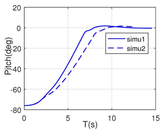
Figure 17.
The simulation comparison of the proposed and latest control algorithm.
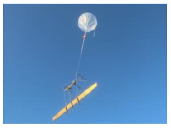
Figure 18.
The rise of balloon-borne solar-powered UAV.
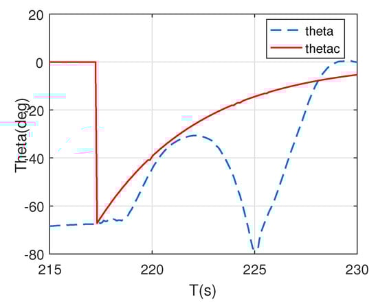
Figure 19.
Pitch angle of the reduced-scale UAV launch test.
By comparing flight tests and evaluating simulation tests, we demonstrate our dynamic model, and the pull-up control model could be applied to solar-powered UAVs with large wingspans.
7. Discussion
Limitations and Future Work: Our study has several limitations. First, we did not perform flight experiments based on the control algorithm proposed in Section 6. Experimental flights comprise complex work involving multiple departments, and this requires coordination that would take up a long period of time. We will leave this to future studies. Second, the balloon-borne UAV’s launch and pull-up control are designed based on the rigid body model with the influence of the elastic deformation of the considered control surface. We will perform these based on the elastic model by considering the elastic deformation of the fuselage to accurately study the pull-up control in the future. Third, the height of our flight experiment is 2000 m, and future studies will try to explore the pull-up control mode at higher altitudes. Fourth, we did not consider the sensitivity of the proposed model relative to some parameters, including the mass characteristic deviation (e.g., position of mass center and the moment of inertia), stability deviation, aerodynamic deviation, constant wind, shear wind, and turbulence disturbances at the aircraft mass’ center, since our task is to explore the available pull-up control algorithm for UAVs with large wingspans. As part of future studies (prior to flight tests), we will take them into consideration to ensure that the aircraft can achieve stable control in the presence of the initial attitude angle and angular rate with respect to the above disturbance conditions.
8. Conclusions
In this paper, an adaptive control model for the pull-up control of a balloon-borne large-wingspan aircraft is proposed. First, we take the effects of the longitudinal elastic deformations with respect to the fuselage into account and establish a longitudinal dynamic model of the balloon-borne large-wingspan aircraft. Then, according to different pull-up stages, we present a pull-up strategy (e.g., three channels’ time-sequential control and different control strategies) that can automatically adapt to the instantaneous azimuth of the aircraft at the moment of launching and the dynamic pressure. Finally, combined with the initial state of the launch and the pull-up completion state of large-scale aircraft, a pitch angle command based on a sinusoidal function is presented. We verify the effectiveness of the proposed algorithm by performing numerical simulation experiments and performing comparisong to the control algorithm utilized in latest experiment.
Author Contributions
Conceptualization, Y.H. (Yanpeng Hu); Formal analysis, X.D.; Project administration, J.G.; Software, Y.H. (Yanfei Hu); Supervision, J.G.; Validation, G.Z.; Writing—original draft, Y.H. (Yanpeng Hu); Writing—review & editing, Y.H. (Yanfei Hu). All authors have read and agreed to the published version of the manuscript.
Funding
This research was supported in part by the Beijing Natural Science Foundation (4222050) and in part by the National Natural Science Foundation of China (62173030).
Institutional Review Board Statement
Not applicable.
Informed Consent Statement
Not applicable.
Conflicts of Interest
The authors declare no conflict of interest.
References
- Wangy, F.; An, Y.W.; Yang, J.H. Current status and development trend of approaching space aircraft. Technol. Found. Natl. Def. 2010, 1, 33–37. [Google Scholar]
- Elson, D.C.; Davison, P. Unmanned Aerial Vehicle and Method of Launching. Available online: https://patents.google.com/patent/WO2014013268A1/un (accessed on 23 July 2022).
- Zheng, H.; Zhao, Z.J.; Zhang, J.Q. Design of unpowered drop model free-flight test control law for an aircraft. Flight Dyn. 2017, 35, 88–96. [Google Scholar]
- Liu, C. Technical Research of Initial State to Level Flight Control for Parachute-Type Small Aircraft; Beijing Institute of Technology: Beijing, China, 2014. [Google Scholar]
- Liu, F. Research on the Attitude Estimation and Fusion Algorithms for Initial State to Level Flight of Small Parachute Aircraft; Beijing Institute of Technology: Beijing, China, 2015. [Google Scholar]
- Tao, Y.J. Development and key technology on near space long voyage solar unmanned aerial vehicle. Aeronaut. Manuf. Technol. 2016, 26–30. [Google Scholar]
- Qineti, Q. Solar aircraft achieves longest unmanned flight. Reinforced Plastics 2010, 54, 9. [Google Scholar]
- Li, C.; Jiang, L. Opto-Electronics A O. Research status and key technology of near space long endurance high altitude solar-powered unmanned air vehicle. China Basic Sci. 2018, 22–31. [Google Scholar]
- Miyazawa, Y.; Harada, A.; Kawaguchi, J.; Ninomiya, T.; Suzuki, H.; Tomita, H. Dynamic programming trajectory optimization and its application to D-SEND #2 low sonic-boom research project. In Proceedings of the AIAA Guidance, Navigation, and Control Conference, Minneapolis, MI, USA, 13–16 August 2012. [Google Scholar] [CrossRef]
- Qu, Z.; Yang, Y.; Li, C.; Hao, Y.; Liu, Y. Study of balloon launched micro air vehicle design and flight test. In Proceedings of the 7th China High Resolution Earth Observation Conference, Changsha, China, 17 November 2020. [Google Scholar]
- Gevers, D.E.; Ratcliff, M.M.; Hatch, J.A. Balloon Launched UAV with Nested Wing for near Space Applications; Aerospace Technology Conference and Exposition: Nagoya, Japan, 2007. [Google Scholar]
- Schwarzbach, M.; Wlach, S.; Laiacker, M. Modifying a scientific flight control system for balloon launched UAV missions. In Proceedings of the 2015 IEEE Aerospace Conference, Big Sky, MT, USA, 7–14 March 2015; pp. 1–10. [Google Scholar] [CrossRef]
- Jacob, J.; Lumpp, J.; Smith, S.; Smith, W. Multidisciplinary design experience of a high altitude inflatable wing UAV for aerospace workforce development. In Proceedings of the AIAA Aerospace Sciences Meeting & Exhibit, New York, NY, USA, 7–10 January 2013. [Google Scholar]
- Favela, K.H.; Tans, P.; Jaeckle, T.H.; Williamson, W.S. Microcollection of gases in a capillary tube: Preservation of spatial and temporal resolution. Anal. Chem. 2012, 84, 8310–8316. [Google Scholar] [CrossRef]
- Steenari, D.; Kuhn, T.; Wlach, S. Vexredus: A student high altitude glider project to demonstrate the capabilities of a blended wing body concept. In Proceedings of the 21st ESA Symposium on European Rocket & Balloon Programmes and Related Research, Tromsø, Norway, 7–12 June 2013; pp. 225–232. [Google Scholar]
- Rautenberg, A.; Graf, M.S.; Wildmann, N.; Platis, A.; Bange, J. Reviewing wind measurement approaches for fifixed-wing unmanned aircraft. Atmosphere 2018, 9, 422. [Google Scholar] [CrossRef]
- Schuyler, T.J.; Gohari, S.M.I.; Pundsack, G.; Berchoff, D.; Guzman, M.I. Using a balloon-launched unmanned glider to validate real-time WRF modeling. Sensors 2019, 19, 1914. [Google Scholar] [CrossRef]
- StratoCat. Stratospheric Balloons Chronological Lists of Launches Worldwide Since 1947. Available online: https://stratocat.com.ar/globos/indexe.html (accessed on 23 July 2022).
- Wang, W.; Zhou, Z.; Zhu, X.P.; Duan, J.B.; Zhang, C. CR approach of nonlinear trim and flight load analysis of very flexible solar powered UAV. J. Northwestern Polytech. Univ. 2015, 33, 566–572. [Google Scholar]
- Wang, W. Exploring Nonlinear Aeroelastic and Flight Dynamics of Solar-Powered UAV; Northwestern Polytechnical University: Xi’an, China, 2015. [Google Scholar]
- Wang, R.; Zhu, X.P.; Zhou, Z. Longitudinal stability and control of highly flexible solar-powered UAV. J. Northwestern Polytech. Univ. 2015, 33, 573–579. [Google Scholar]
- Hu, Y.; Guo, J.; Meng, W.; Liu, G.; Xue, W. Longitudinal control for balloon-borne launched solar powered UAVs in near-space. J. Syst. Sci. Complex. 2022, 35, 802–819. [Google Scholar] [CrossRef]
- Hu, Y.P.; Yang, Y.P.; Ma, X.P. Computational optimal launching control for ballon-borne solar-powered UAVs in near-space. Sci. Prog. 2019, 9, 1–19. [Google Scholar]
- Ma, D.L.; Zhang, L.; Yang, M.Q.; Xia, X.; Wang, S. Review of key technologies of ultra-long-endurance solar powered unmanned aerial vehicle. Acta Aeronaut. Astronaut. Sin. 2020, 41, 34–63. [Google Scholar]
- Li, F.; Bai, P. Low Reynolds Number Aerodynamics of Air Vehicles; China Astronautic Publishing House: Beijing, China, 2017; pp. 1–185. [Google Scholar]
- Bai, P.; Cui, E.J.; Zhou, W.J.; Li, F. Numerical simulation of laminar separation bubble over 2D airfoil at low Reynolds number. Acta Aerodyn. Sin. 2006, 24, 416–424. [Google Scholar]
- Duan, Z.Y.; Wang, W.; Geng, J.Z.; Jian, Z.; Junfu, L. Challenges of high efficiency aerodynamics design for HALE powered UAV. Acta Aerodyn. Sin. 2017, 35, 156–171. [Google Scholar]
- Li, C.F.; Jiang L, H. Review of near space long endurance solar-powered unmanned aerial vehicle in aerodynamic study. World Sci-Tech R&D 2018, 40, 386–398. [Google Scholar]
- Lissamanp, B.S. Low-Reynolds-number airfoils. Annu. Rev. Fluid Mech. 2003, 15, 223–239. [Google Scholar] [CrossRef]
- Selig, M.; Guglielmo, J.; Broern, A.; Giguere, P. Experiments on airfoils at low Reynolds numbers. In Proceedings of the 34th Aerospace Sciences Meetings and Exhibit, Reston, VA, USA, 26–28 September 1996; p. 62. [Google Scholar]
- Mueller, T.J.; Batil, S.M. Experimental studied of separation on a two-dimensional airfoil at low Reynolds numbers. Aiaa J. 1982, 20, 457–463. [Google Scholar] [CrossRef]
- Tan, S.P.; Guo, J.; Zhao, Y.L.; Zhang, J.F. Adaptive control with saturation-constrainted observations for drag-free satellites—A set-valued identification approach. Sci. China Inf. Sci. 2021, 64, 202202. [Google Scholar] [CrossRef]
- Yang, F.; Tan, S.P.; Xue, W.C.; Guo, J.; Zhao, Y.L. Extended state filtering with saturation-constrainted observations and active disturbance rejection control of position and attitude for drag-free satellites. Acta Autom. Sin. 2020, 46, 2337–2349. [Google Scholar]
- Hu, Y.P.; Guo, J.; Ying, P.; Zeng, G.N.; Chen, N.Y. Nonlinear control of a single tail tilt servomotor tri-rotor ducted VTOL-UAV. Aerospace 2022, 9, 296. [Google Scholar] [CrossRef]


Publisher’s Note: MDPI stays neutral with regard to jurisdictional claims in published maps and institutional affiliations. |
© 2022 by the authors. Licensee MDPI, Basel, Switzerland. This article is an open access article distributed under the terms and conditions of the Creative Commons Attribution (CC BY) license (https://creativecommons.org/licenses/by/4.0/).