
Three-Dimensional Modeling of Soil-Structure Interaction for a Bridge Founded on Caissons under Seismic Conditions


Abstract
1. Introduction
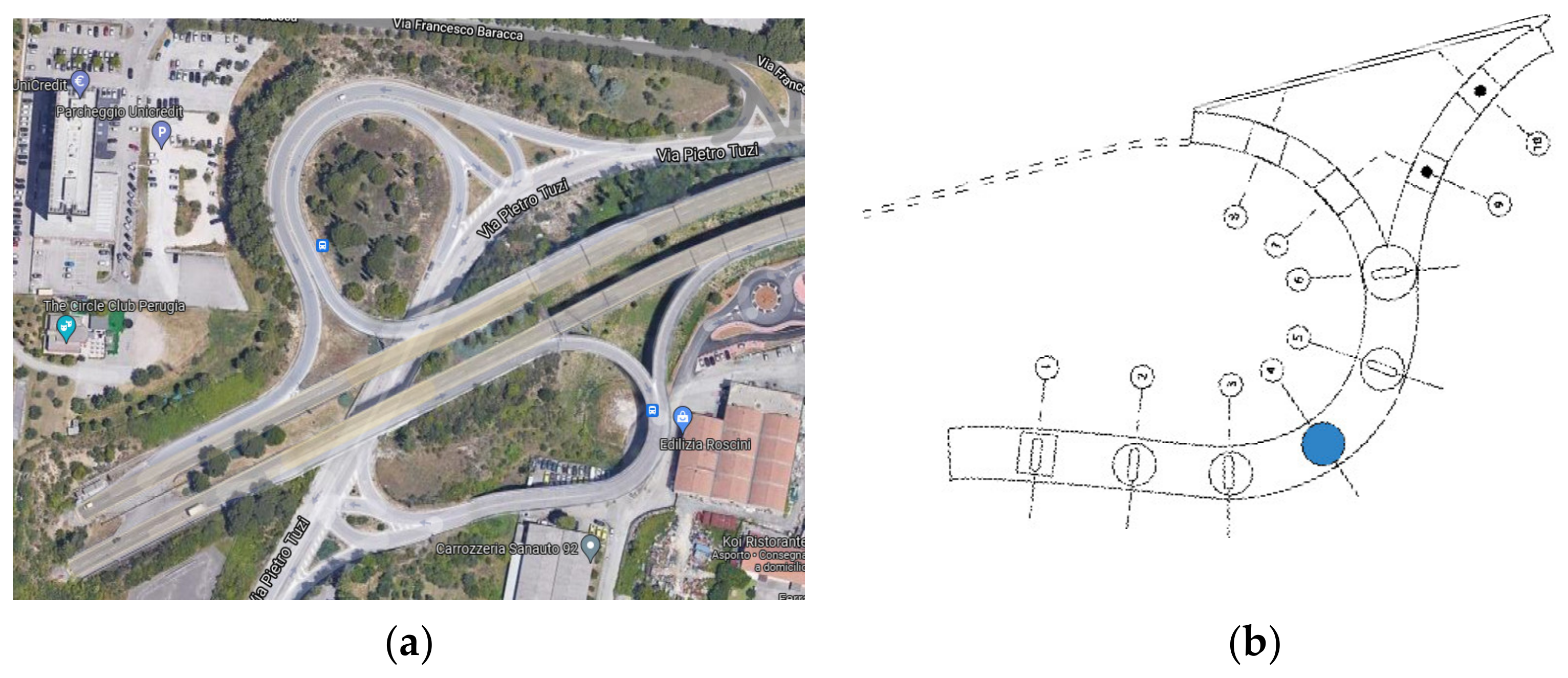
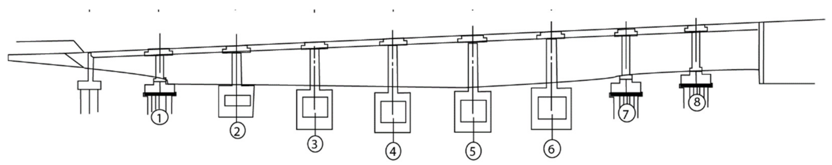
2. Study-Case
3. Seismic Input
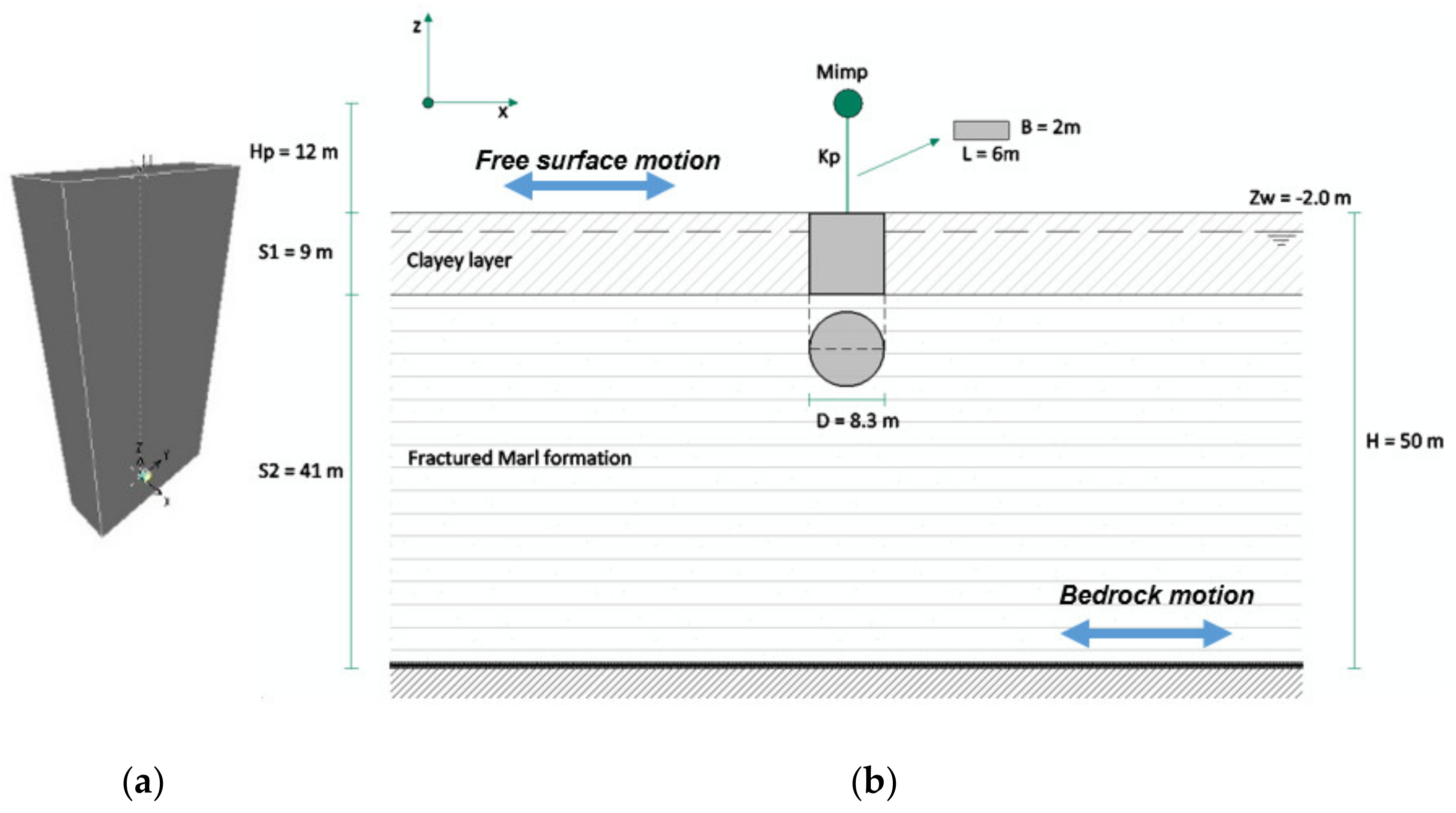
4. Numerical Modeling
- Application of a lumped load at the top of the pier (in the direction of the system’s highest stiffness, i.e., orthogonal with respect to the deck direction) and analysis of the system free vibration, to determine the structure’s natural frequency at small strains;
- Application of the selected earthquake in the direction of the system’s highest stiffness (orthogonal with respect to the deck direction) and dynamic analysis of the system response.
4.1. SAP Model
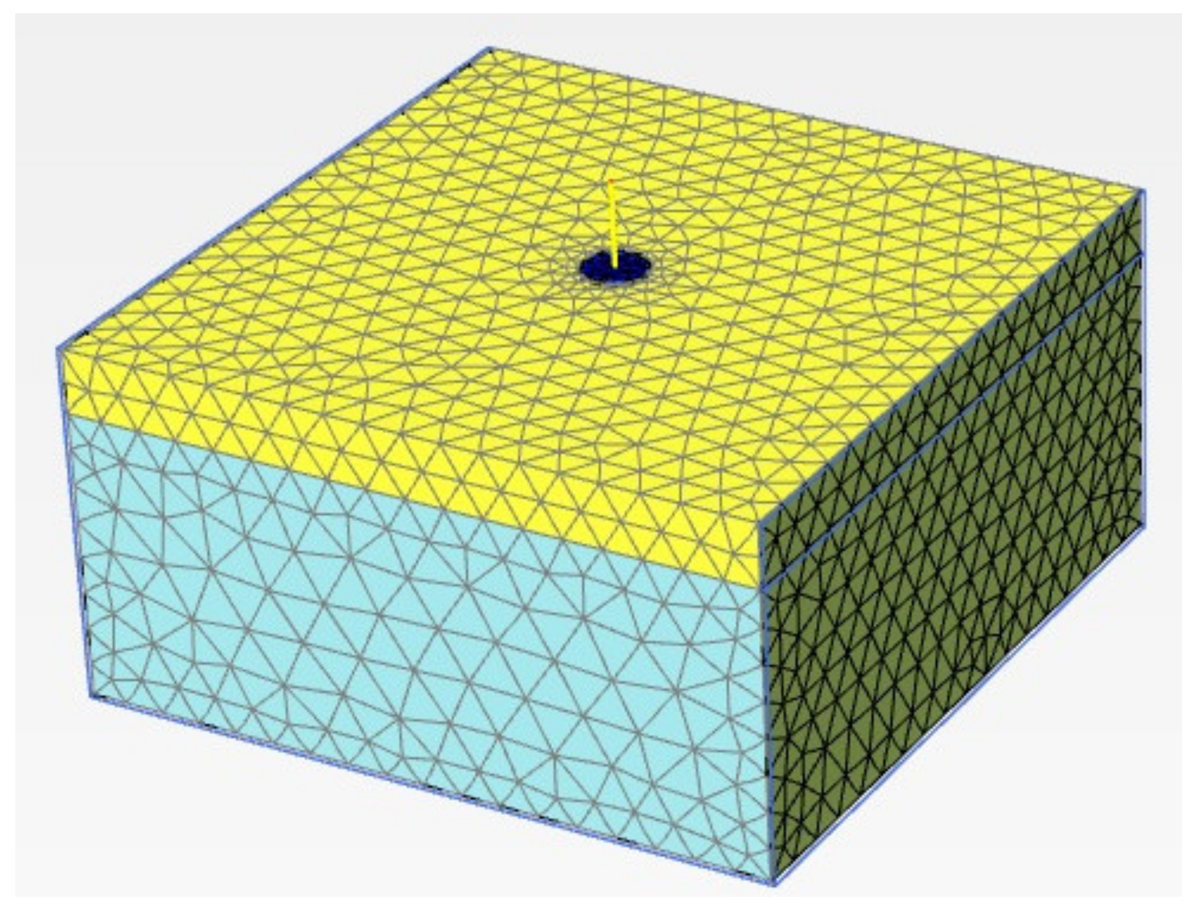
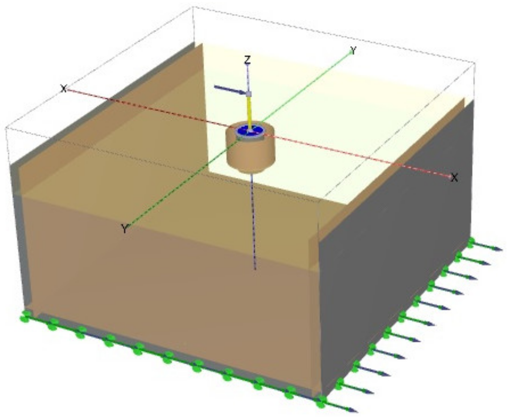
4.2. PLAXIS3D Model
5. Results
- Natural periods under free vibrations and system period under seismic conditions, the latter computed as the period corresponding to the maximum value of the ratio between the pseudo-acceleration response spectrum with 5% damping at the top of the pier and the one at the base of the pier [47];
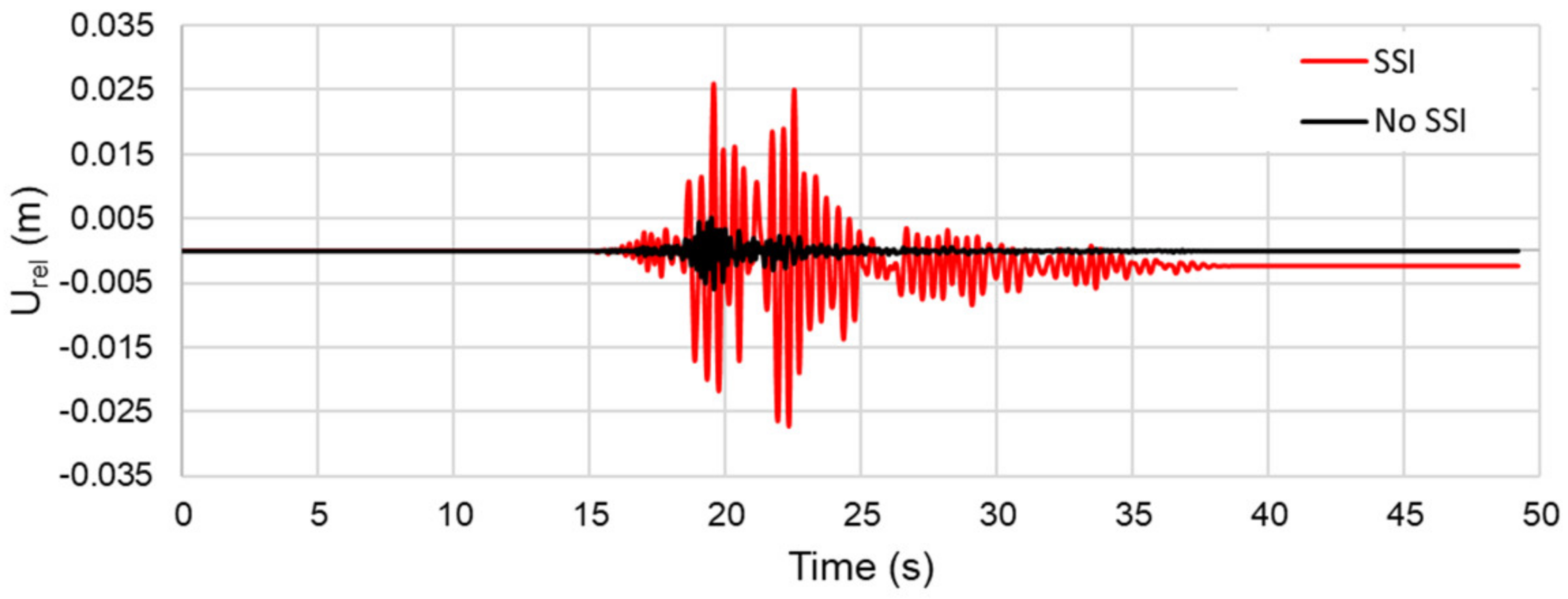
- Relative horizontal displacement (Urel) time-histories, evaluated as the difference between the absolute horizontal displacement at the top (Utop) and base (Ubas) of the pier;
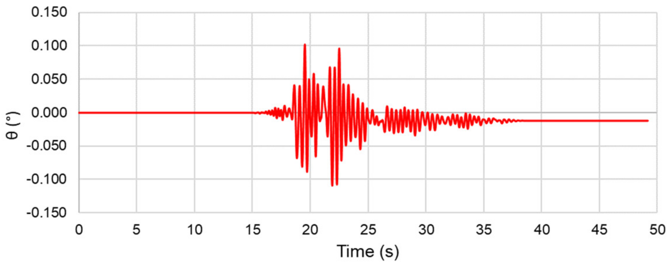
- Rotation time-history of the pier;
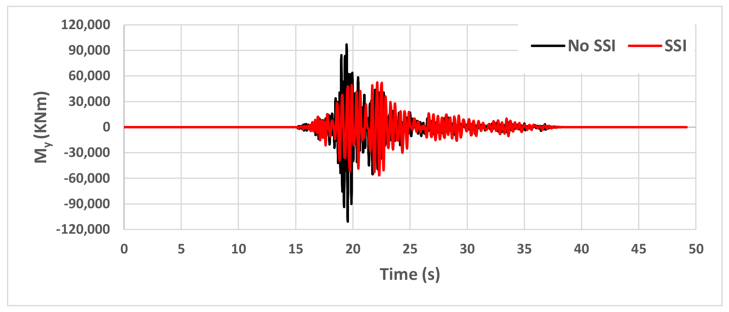
- Moment and shear time-histories at the pier base.
6. Conclusions and Perspectives
Author Contributions
Funding
Institutional Review Board Statement
Informed Consent Statement
Data Availability Statement
Acknowledgments
Conflicts of Interest
References
- De Angelis, A.; Mucciacciaro, M.; Pecce, M.R.; Sica, S. Influence of SSI on the Stiffness of Bridge Systems Founded on Caissons. J. Bridge Eng. 2017, 22, 4017045. [Google Scholar] [CrossRef]
- Gerolymos, N.; Gazetas, G. Static and dynamic response of massive caisson foundations with soil and interface nonlinearities—validation and results. Soil Dyn. Earthq. Eng. 2006, 26, 377–394. [Google Scholar] [CrossRef]
- Gerolymos, N.; Gazetas, G. Winkler model for lateral response of rigid caisson foundations in linear soil. Soil Dyn. Earthq. Eng. 2006, 26, 347–361. [Google Scholar] [CrossRef]
- Varun; Assimaki, D.; Gazetas, G. A simplified model for lateral response of large diameter caisson foundations—Linear elastic formulation. Soil Dyn. Earthq. Eng. 2009, 29, 268–291. [Google Scholar] [CrossRef]
- Zafeirakos, A.; Gerolymos, N.; Gazetas, G. The role of soil and interface nonlinearities on the seismic response of caisson supported bridge piers. In Proceedings of the 5th International Conference on Geotechnical Earthquake Engineering, Santiago, Chile, 13 January 2011. [Google Scholar]
- Buscarnera, G.; Nova, R.; Vecchiotti, M.; Tamagnini, C.; Salciarini, D. Settlement analysis of wind turbines. In Soil-Foundation-Structure Interaction; CRC Press: Boca Raton, FL, USA, 2010; pp. 163–170. [Google Scholar]
- Grange, S.; Salciarini, D.; Kotronis, P.; Tamagnini, C. A comparison of different approaches for the modelling of shallow foundations in seismic soil-structure interaction problems. In Numerical Methods in Geotechnical Engineering, Proceedings of the 7th European Conference on Numerical Methods in Geotechnical Engineering, Trondheim, Norway, 2–4 June 2010; CRC Press: Boca Raton, FL, USA, 2010; pp. 405–410. [Google Scholar]
- Venanzi, I.; Salciarini, D.; Tamagnini, C. The effect of soil–foundation–structure interaction on the wind-induced response of tall buildings. Eng. Struct. 2014, 79, 117–130. [Google Scholar] [CrossRef]
- Salciarini, D.; Frizza, M.; Tamagnini, C.; Arroyo, M.; Abadìas, D. Macroelement Modeling of SSI Effects on Offshore Wind Turbines Subject to Large Number of Loading Cycles. Procedia Eng. 2016, 158, 332–337. [Google Scholar] [CrossRef][Green Version]
- Gazetas, G. Foundation Vibrations, Foundation Engineering Handbook; Fang, H.Y., Ed.; Van Nostrand Reinhold: New York, NY, USA, 1991; Chapter 15; pp. 553–592. [Google Scholar]
- Mylonakis, G.; Gazetas, G. Seismic soil-structure interaction: Beneficial or detrimental? J. Earthq. Eng. 2000, 4, 277–301. [Google Scholar] [CrossRef]
- Wolf, J.P. Soil Structure Interaction; Englewood Cliffs, N.J., Ed.; Prentice-Hall: Hoboken, NL, USA, 1985. [Google Scholar]
- Chellini, G.; Nardini, L.; Salvatore, W. Dynamical identification and modelling of steel-concrete composite high-speed railway bridges. Struct. Infrastruct. Eng. 2011, 7, 823–841. [Google Scholar] [CrossRef]
- Gara, F.; Regni, M.; Roia, D.; Carbonari, S.; Dezi, F. Evidence of coupled soil-structure interaction and site response in continuous viaducts from ambient vibration tests. Soil Dyn. Earthq. Eng. 2019, 120, 408–422. [Google Scholar] [CrossRef]
- Marrongelli, G.; Gentile, C.; Saisi, A. Anomaly Detection Based on Automated OMA and Mode Shape Changes: Application on a Historic Arch Bridge Structural Integrity. In International Conference on Arch Bridges; Springer: Cham, Switzerland, 2020; Volume 11, pp. 447–455. [Google Scholar]
- Zampieri, P.; Simoncello, N.; Gonzalez-Libreros, J.; Pellegrino, C. Evaluation of the vertical load capacity of masonry arch bridges strengthened with FRCM or SFRM by limit analysis. Eng. Struct. 2020, 225, 111135. [Google Scholar] [CrossRef]
- Ciampoli, M.; Pinto, E. Effects of soil-structure interaction on inelastic seismic response of bridge piers. J. Struct. Eng. 1995, 121, 806–814. [Google Scholar] [CrossRef]
- Dicleli, M.; Lee, J.Y.; Mansour, M. Importance of soil-bridge interaction modeling in seismic analysis of seismic-isolated bridges. In Proceedings of the 13th World Conference on Earthquake Engineering, Vancouver, BC, Canada, 1–6 August 2004. [Google Scholar]
- Jeremic, B.; Kunnath, S.; Xiong, F. Influence of soil foundation-structure interaction on seismic response of the I-880 viaduct. Eng. Struct. 2004, 26, 391–402. [Google Scholar] [CrossRef]
- Makris, N.; Badoni, D.; Delis, E.; Gazetas, G. Prediction of observed bridge response with soil-pile-structure interaction. J. Struct. Eng. 1995, 120, 2992–3011. [Google Scholar] [CrossRef]
- Veletsos, A.S.; Meek, J.W. Dynamic behaviour of building-foundation systems. Earthq. Eng. Struct. Dyn. 1974, 3, 121–138. [Google Scholar] [CrossRef]
- Gaudio, D.; Rampello, S. The influence of soil plasticity on the seismic performance of bridge piers on caisson foundations. Soil Dyn. Earthq. Eng. 2019, 118, 120–133. [Google Scholar] [CrossRef]
- Mucciacciaro, M.; Gerolymos, N.; Sica, S. Seismic response of caisson-supported bridge piers on viscoelastic soil. Soil Dyn. Earthq. Eng. 2020, 139, 106341. [Google Scholar] [CrossRef]
- Tsigginos, C.; Gerolymos, N.; Assimaki, D.; Gazetas, G. Seismic response of bridge pier on rigid caisson foundation in soil stratum. Earthq. Eng. Eng. Vib. 2008, 7, 33–43. [Google Scholar] [CrossRef]
- Lai, C.G.; Martinelli, M. Soil-Structure Interaction Under Earthquake Loading: Theoretical Framework. ALERT Dr. Sch. Soil-Struct. Interact. 2013, 2013, 3–43. [Google Scholar]
- Salciarini, D.; Grange, S.; Tamagnini, C.; Kotronis, P. Macroelements for Soil–Structure Interaction. In Deterministic Numerical Modeling of Soil Structure Interaction; Grange, S., Salciarini, D., Eds.; ISTE: London, UK; Wiley: Oxford, UK, 2022. [Google Scholar]
- Mylonakis, G.; Nikolaou, A. Soil-Pile-Bridge Seismic Interaction: Kinematic and Inertial Effects. Part I: Soft Soil. Earthq. Eng. Struct. Dyn. 1997, 26, 337–359. [Google Scholar] [CrossRef]
- Mylonakis, G.; Nikolaou, S.; Gazetas, G. Footings under seismic loading: Analysis and design issues with emphasis on bridge foundations. Soil Dyn. Earthq. Eng. 2006, 26, 824–853. [Google Scholar] [CrossRef]
- Wolf, P.W. Foundation Vibration Analysis Using Simple Physical Models; Pearson Education: London, UK, 1994; p. 464. [Google Scholar]
- Davies, T.G.; Budhu, M. No AccessNon-linear analysis of laterally loaded piles in heavily overconsolidated clays. Géotechnique 1986, 36, 527–538. [Google Scholar] [CrossRef]
- Pender, M.J. Earthquake resistant design of foundations. Bull. N. Z. Soc. Earthq. Eng. 1996, 29, 155–171. [Google Scholar] [CrossRef]
- Nova, R.; Montrasio, L. Settlements of shallow foundations on sand. Geotechnique 1991, 41, 243–256. [Google Scholar] [CrossRef]
- Tamagnini, C.; Salciarini, D.; Ragni, R. Implementation of a 6-DOF hypoplastic macroelement in a finite element code. In Computational Geomechanics, COMGEO III, Proceedings of the 3rd International Symposium on Computational Geomechanics, Krakow, Poland, 21–23 August 2013; International Centre for Computational Engineering: Rhodes, Greece, 2013; pp. 534–544. Available online: http://www.ic2e.org/wp-content/uploads/2019/03/Proceedings-ComGeo-3.pdf (accessed on 27 September 2022).
- Salciarini, D.; Bienen, B.; Tamagnini, C. Incorporating scale effects in shallow footings in a hypoplastic macroelement model. In Numerical Methods in Geotechnical Engineering, Proceedings of the 8th European Conference on Numerical Methods in Geotechnical Engineering, NUMGE 2014, Delft, The Netherlands, 18–20 Jun 2014; CRC/Balkema: Leiden, The Netherlands, 2014; Volume 1, pp. 397–402. [Google Scholar]
- Grange, S. Simplified modeling strategies for soil-structure interaction problems: The Macro-Element Concept. ALERT Dr. Sch. Soil-Struct. Interact. 2013, 2013, 195–217. [Google Scholar]
- Ritesh, G. Behaviour of Monopile Under Combined Cycling Load. Ph.D. Thesis, Universitè Grenoble Alpes, Grenoble, France, 2020. [Google Scholar]
- Salciarini, D.; Bienen, B.; Tamagnini, C. A hypoplastic macroelement for shallow foundations subject to six-dimensional loading paths. In Computational Geomechanics, COMGEO II, Proceedings of the 2nd International Symposium on Computational Geomechanics, Dubrovnik, Croatia, 27–29 April 2011; International Centre for Computational Engineering: Rhodes, Greece, 2011; pp. 721–733. [Google Scholar]
- Kita, A.; Lupattelli, A.; Venanzi, I.; Salciarini, D.; Ubertini, F. The role of seismic hazard modeling on the simplified structural assessment of an existing concrete gravity dam. Structures 2021, 34, 4560–4573. [Google Scholar] [CrossRef]
- Breccolotti, M.; Materazzi, A.L.; Salciarini, D.; Tamagnini, C.; Ubertini, F. Vibrations induced by the new underground railway line in Palermo, Italy: Experimental measurements and FE modeling. In Proceedings of the 8th International Conference on Structural Dynamics, EURODYN 2011, Leuven, Belgium, 4–6 July 2011; pp. 719–726. [Google Scholar]
- Cattoni, E.; Salciarini, D.; Tamagnini, C. A Generalized Newmark Method for the assessment of permanent displacements of flexible retaining structures under seismic loading conditions. Soil Dyn. Earthq. Eng. 2018, 117, 221–233. [Google Scholar] [CrossRef]
- Kozielova, M.; Marcalikova, Z.; Mateckova, P.; Sucharda, O. Numerical Analysis of Reinforced Concrete Slab with Subsoil. Civ. Environ. Eng. 2020, 16, 107–118. [Google Scholar] [CrossRef]
- Iervolino, I.; Galasso, C.; Cosenza, E. REXEL: Computer aided record selection for code-based seismic structural analysis. Bull. Earthq. Eng. 2009, 8, 339–362. [Google Scholar] [CrossRef]
- SAP2000 [Computer Software], Computers & Strcutures, Inc.: Walnut Creek, CA, USA, 2000.
- Plaxis 3D Foundation [Computer Software], Bentley: Crewe, UK, 2000.
- Zafeirakos, A.; Gerolymos, N. On the seismic response of under-designed caisson foundations. Bull. Earthq. Eng. 2013, 11, 1337–1372. [Google Scholar] [CrossRef]
- Kulhawy, F.H.; Mayne, P.W. Manual on Estimating Soil Properties for Foundation Design; Cornell University: Ithaca, NY, USA, 1990. [Google Scholar]
- Elia, G.; Rouinia, M. Seismic Performance of Earth Embankment Using simple and advanced numerical approaches. J. Geotech. Geoenviron. Eng. 2013, 139, 115–1129. [Google Scholar] [CrossRef]
- Crespi, P.; Zucca, M.; Longarini, N.; Giordano, N. Seismic Assesment of Six Typologies of Existing RC Bridges. Infrastructures 2020, 5, 52. [Google Scholar] [CrossRef]
- Yazdani, M.; Jahangiri, V.; Marefat, M.S. Seismic performance assessment of plain concrete arch bridges under near-field earthquakes using incremental dynamic analysis. Eng. Fail. Anal. 2019, 106, 104170. [Google Scholar] [CrossRef]


| Code | Fa | D (s) | PGA | IA (cm/s) | fPEAK (Hz) | fMEAN (Hz) | TMEAN (s) | D* (s) |
|---|---|---|---|---|---|---|---|---|
| n. 1 | 1.5 | 44.17 | 0.326 | 0.87 | 2.66 | 4.48 | 0.304 | 4.609 |
| n. 2 | 1.0 | 44.17 | 0.214 | 0.37 | 2.66 | 4.48 | 0.304 | 4.609 |
| n. 3 | 0.75 | 44.17 | 0.163 | 0.21 | 2.66 | 4.48 | 0.304 | 4.609 |
| n. 4 | 0.4 | 44.17 | 0.086 | 0.06 | 2.66 | 4.48 | 0.304 | 4.609 |
| Parameter | Symbol | Clayey F. | Marly F. | r.c. | Unit |
|---|---|---|---|---|---|
| Constit. model | - | HS-small | Mohr-Coulomb | Linear Elastic | - |
| Dry unit weight | γs | 17 | 20 | 25/22 | kN/m3 |
| Sat unit weight | γsat | 20 | 22 | kN/m3 | |
| Mod. sec Mod. tan Mod. unl/rel | 20 20 100 | - - - | MPa MPa MPa | ||
| Young Modulus | E′ | - | 1350 | 30,000/25,000 | MPa |
| Cohesion Friction angle | c′ ϕ′ | 20 25 | 50 28 | - - | kN/m3 ° |
| Small-strain stiff. Shear strain level Poisson coeff. Damp. Rayleigh | G′ref0 γ0.7 ν′ δ | 150 0.1 × 10⁻³ 0.25 3% | - - 0.35 5% | - - 0.2 5% | MPa - - - |
| Urel,1.5 (m) | Urel,1.0 (m) | Urel,0.75 (m) | Urel,0.4 (m) | Ures,1.5 (m) | Ures,1.0 (m) | Ures,0.75 (m) | Ures,0.4 (m) | |
|---|---|---|---|---|---|---|---|---|
| SSI | 0.027 | 0.025 | 0.019 | 0.009 | 0.0024 | 0.0020 | 0.0012 | 0.0003 |
| No-SSI | 0.0084 | 0.0068 | 0.0058 | 0.0038 | -- | -- | -- | -- |
| Ratio | 3.21 | 3.67 | 3.27 | 2.36 | -- | -- | -- | -- |
| Utop,1.5 (m) | Utop,1.0 (m) | Utop,0.75 (m) | Utop,0.4 (m) | Ubas,1.5 (m) | Ubas,1.0 (m) | Ubas,0.75 (m) | Ubas,0.4 (m) | |
|---|---|---|---|---|---|---|---|---|
| SSI | 0.078 | 0.059 | 0.048 | 0.021 | 0.057 | 0.040 | 0.032 | 0.016 |
| No-SSI | 0.0084 | 0.0068 | 0.0058 | 0.0038 | -- | -- | -- | -- |
| Ratio | 9.28 | 8.67 | 8.27 | 5.52 | -- | -- | -- | -- |
| Mmax,1.5 (kNm) | Mmax,1.0 (kNm) | Mmax,0.75 (kNm) | Mmax,0.4 (kNm) | |
|---|---|---|---|---|
| SSI | 56,053 | 55,475 | 50,895 | 32,652 |
| No-SSI | 159,100 | 129,800 | 109,500 | 71,620 |
| Ratio | 0.35 | 0.42 | 0.46 | 0.45 |
| Vmax,1.5 (kN) | Vmax,1.0 (kN) | Vmax,0.75 (kN) | Vmax,0.4 (kN) | |
|---|---|---|---|---|
| SSI | 5097 | 5068 | 4911 | 3074 |
| No-SSI | 13,260 | 10,820 | 9126 | 5209 |
| Ratio | 0.38 | 0.46 | 0.53 | 0.59 |
Publisher’s Note: MDPI stays neutral with regard to jurisdictional claims in published maps and institutional affiliations. |
© 2022 by the authors. Licensee MDPI, Basel, Switzerland. This article is an open access article distributed under the terms and conditions of the Creative Commons Attribution (CC BY) license (https://creativecommons.org/licenses/by/4.0/).
Share and Cite
Pauselli, D.; Salciarini, D.; Ubertini, F. Three-Dimensional Modeling of Soil-Structure Interaction for a Bridge Founded on Caissons under Seismic Conditions. Appl. Sci. 2022, 12, 10904. https://doi.org/10.3390/app122110904
Pauselli D, Salciarini D, Ubertini F. Three-Dimensional Modeling of Soil-Structure Interaction for a Bridge Founded on Caissons under Seismic Conditions. Applied Sciences. 2022; 12(21):10904. https://doi.org/10.3390/app122110904
Chicago/Turabian StylePauselli, Davide, Diana Salciarini, and Filippo Ubertini. 2022. "Three-Dimensional Modeling of Soil-Structure Interaction for a Bridge Founded on Caissons under Seismic Conditions" Applied Sciences 12, no. 21: 10904. https://doi.org/10.3390/app122110904
APA StylePauselli, D., Salciarini, D., & Ubertini, F. (2022). Three-Dimensional Modeling of Soil-Structure Interaction for a Bridge Founded on Caissons under Seismic Conditions. Applied Sciences, 12(21), 10904. https://doi.org/10.3390/app122110904