Article

Dynamic Measurement of Patellofemoral Compression Forces: A Novel Method for Patient-Specific Patella Resurfacing in Total Knee Replacement

1
Istituto Clinico Città Studi, Via Niccolò Jommelli, 17, 20131 Milano, Italy
2
School of Engineering Sciences, University of Southampton, University Road, Southampton SO17 1BJ, UK
3
Department of Orthopaedic Surgery, University of Pittsburgh Medical Center, 5200 Centre Ave., Suite 415, Pittsburgh, PA 15232, USA
4
Eventum Orthopaedics Ltd., Bradford LS29 8QH, UK
5
ONYX InSight, Technology Centre, UoN Innovation Park, Triumph Road, Nottingham NG7 2TU, UK
*
Author to whom correspondence should be addressed.
Appl. Sci. 2022, 12(20), 10584; https://doi.org/10.3390/app122010584
Submission received: 20 September 2022 / Revised: 13 October 2022 / Accepted: 18 October 2022 / Published: 20 October 2022

Abstract

:
Functional dissatisfaction following total knee replacement (TKR) is recorded as high as 20%. The majority of these patients report anterior knee pain (AKP) as the main source of dissatisfaction. Elevated patellofemoral compression forces and soft tissue extensor hood strain have been implicated in the generation of significant AKP. A novel method of assessing and measuring patellofemoral compression forces dynamically in the native and resurfaced patella for TKR in four different quadrants of the patella is described. Results are reported from an in vitro model and cadaveric studies in the native and resurfaced knee. Patellofemoral compression forces are shown to be characteristic and consistent over repeated assessments in the native knee. Placement of a TKR significantly alters this pattern. Furthermore, over-stuffing or under-stuffing the resurfaced patella also significantly alters the nature and magnitude of patellofemoral compression forces. These studies may lead to an improved understanding of the nature of AKP following TKR, and using this assessment tool presents an opportunity to more effectively balance the third space, reproduce the native patellofemoral forces, and subsequently reduce AKP following TKR.

1. Introduction

Outcomes of total knee replacement (TKR) remain suboptimal, with 10–20% of patients continuing to experience pain or functional limitations after primary TKR [1], despite good long-term survivorship [2]. Approximately 45% of patients dissatisfied with TKR report anterior knee pain (AKP) affecting their daily activities [3] which is likely related to patellofemoral complications. Patients suffering from AKP have difficulties with activities that increase patellofemoral joint (PFJ) forces such as walking up and down stairs, rising from a seated position, exiting a car or cycling [4]. Patellofemoral complications are historically one of the most common reasons for poor TKR outcome [5]. AKP appears to occur with equal incidence as patellofemoral complications, independent to whether the patella is resurfaced or left native [6]. The patella itself is relatively poorly innervated, whereas the surrounding extensor hood of soft tissue is highly sensitive to increased strain.
Many factors affect the balance of the PJF during TKR including the amount of trochlea resection, the rotation and size of the femoral component. The distal femoral resection and tibial resection influence the joint line, which can change soft tissue tension of the extensor mechanism. When the patella is resurfaced, the amount of patella resection, size, shape and placement of the patella component influence patella tracking and soft tissue tension. Patella under-resection and thereby over-stuffing of the PFJ can cause chronic postoperative AKP and decreased range of motion due to higher than physiologic extensor mechanism forces [7]. Patella over-resection increases the risk for fracture and may lead to under-tensioning the PFJ, resulting in lower than physiological extensor mechanism forces and muscle pain [8]. Patella maltracking is multifactorial and is defined as abnormal tracking of the patella in the femoral groove during knee flexion and extension and can lead to increased wear of the patellar component, subluxation and dislocation [9].
Despite these findings, the PFJ and extensor mechanism’s role as primary contributors to overall knee function is often overlooked, and limited attention has been paid to improving balancing and cutting techniques for the PFJ during TKR. Currently, with traditional surgical techniques, there is no method of quantifying or addressing patella compression forces. While prior studies have described changes in Q-angle and fluoroscopic patellar angle measurements to assess the PFJ postoperatively [10,11], a dynamic, intraoperative assessment of PFJ forces during TKR has not been described. An intraoperative means of assessing PFJ forces during TKR could allow adjustments of the patella cut depth and angle to more closely replicate native PFJ kinematics, which may improve overall patient outcomes and decrease PFJ-related complications.
The current study utilized a novel PFJ load sensor device that resembles a patella implant component. When applied to the patella, the sensor is capable of dynamically assessing PFJ forces before and after placement of tibial and femoral TKR components, which can allow for patella cut adjustments and reproduction of physiologic PFJ and extensor mechanism forces. The aims of this study were (1) to characterize changes in PFJ forces in an experimental in vitro setup and in a human cadaveric model before and after TKR component placement and (2) to assess whether the use of novel PFJ cutting guides can reproduce physiologic PFJ forces in a cadaveric model. The study hypothesized that native and postoperative resection PFJ forces can be measured and differ based on patella implant thickness and angulation of the patella cut. The goal of this translational research is to develop a system that can improve TKR outcomes by balancing the PFJ and extensor mechanism as an integral but often overlooked part of TKR surgery. Significant patient benefits might result, based on data that patella over/under-loading is closely associated with poor functional outcome [12,13,14].

2. Materials and Methods

2.1. Patellofemoral Joint Load Sensor

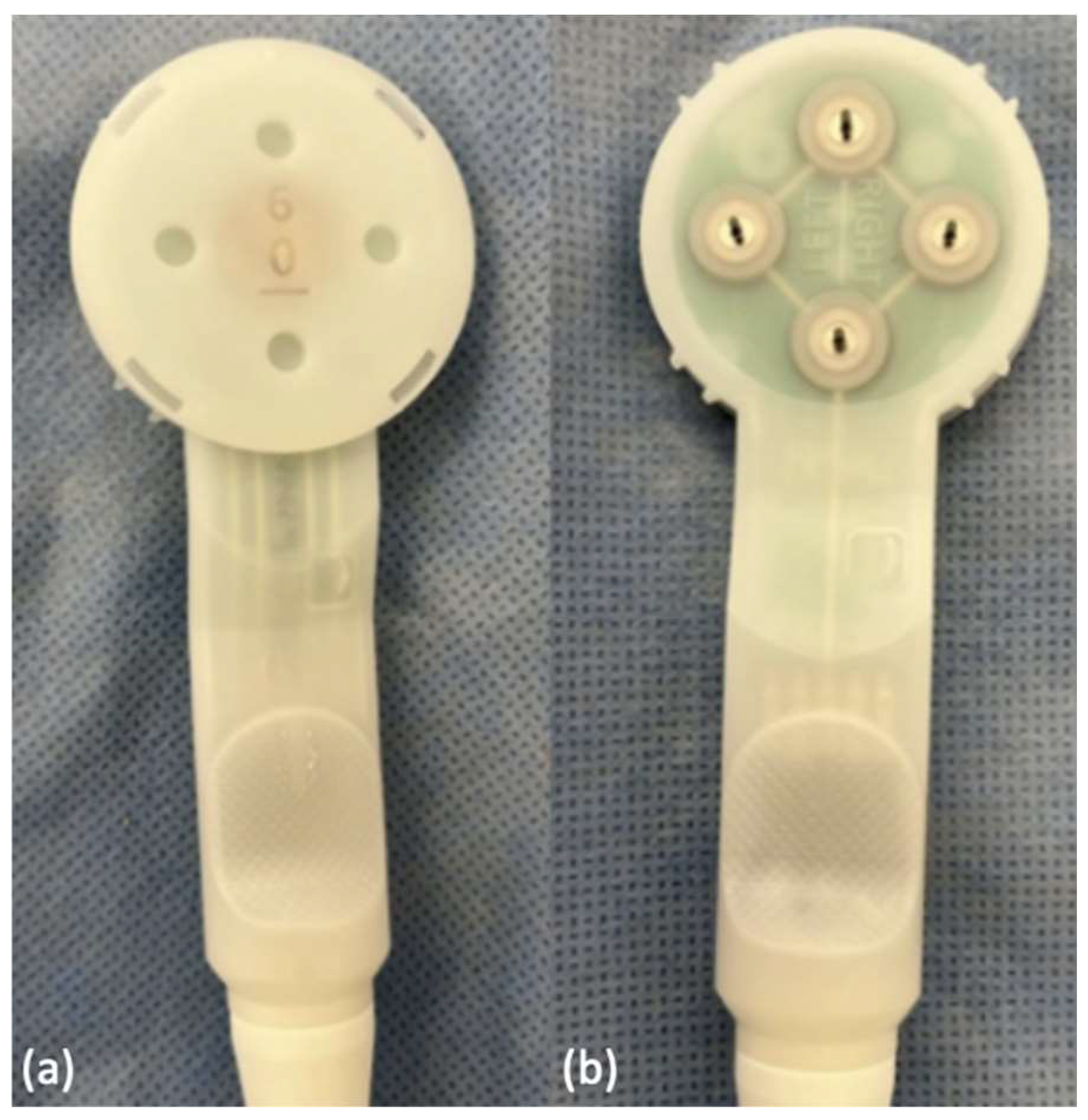
The novel PFJ load sensor (quad sense, Eventum Orthopaedics Ltd., Ilkley, UK) was initially developed in 2021 and consists of a paddle with four evenly placed pressure sensors in the superior, inferior, medial and lateral quadrants (Figure 1a) that can be attached to the underside of the everted patella via four stainless steel tines (Figure 1b). The sensor itself is constructed from ABS resin contoured into a disc matching the shape of the patellar undersurface, and is designed to measure compressive forces in four separate quadrants of the patellofemoral joint (Figure 2). Adjustment shims with different thicknesses (6 mm, 7 mm, 8 mm, 9 mm) and angles (neutral, 1.25 degrees, 2.5 degrees) can be attached to the underside of the sensor paddle. Sensor data is captured after a trial of knee flexion-extension is generated, and usually three trials can be performed in a single 12 s recording period. This sensor data is recorded and a visual plot of sensor force against time can be generated in real time and displayed on a panel PC, with four lines shown corresponding to each of the four quadrant sensors, respectively.

2.2. In Vitro Experimental Set-Up

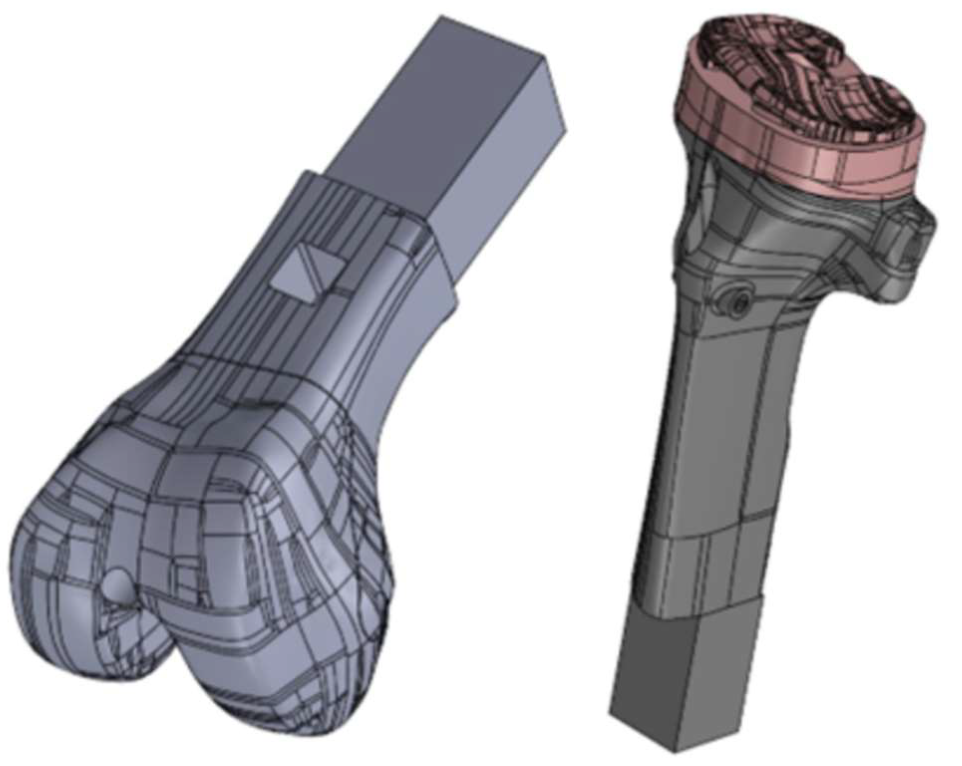
An in vitro evaluation of the sensor was conducted utilizing a model knee. A model Left Cadaver Leg Version 3 (Medical Models, Bristol, UK) with custom 3D printed femoral and tibial component inserts was used (Figure 3). A simulated patella with tendons was attached to the model knee, with a spring used to simulate the quadriceps tension. The spring had a free length of 107 mm and a 1.64 mm wire gauge diameter. To accommodate the sensor, the patella was resected by 6 mm, using the lateral facet as reference. Sensor readings were taken using the 6 mm, 7 mm, 8 mm, 9 mm and 6 mm 2.5° shims, following a methodology of moving the model knee through full flexion and extension three times, at a consistent pace and flexion angle.

2.3. Cadaveric Patella Load Assessment

The current study utilized two pelvis-to-toe, unpreserved cadaveric specimens (Specimen 1: 75 year old male, body mass index 22 kg/m2, no previous knee surgery, mild bilateral medial compartment arthritis; Specimen 2: 76 year old male, body mass index 26 kg/m2, no previous knee surgery, mild right medial compartment arthritis, moderate left tricompartmental arthritis) to test whether the quad sense device was able to capture PFJ forces in a proposed TKR workflow to adjust the patella cut with a custom patella clamp to reproduce more physiologic PFJ forces during TKR. On each extremity, a standard medial arthrotomy approach to the knee was performed. The patella was mobilized and everted. A preliminary 6 mm patella cut was made using a patella clamp (Enztec, Premium Patella Saw Guide, Christchurch, New Zealand) with a custom cutting guide attached to the clamp for a 6 mm resection depth and a standard oscillating saw (Figure 4). The quad sense sensor with 6 mm neutral shim was then attached to the cut undersurface of the patella using four metal tines as part of the sensor paddle. Force data of the native PFJ was then recorded from three range of motion trials from full extension to full flexion in all four quadrants of the sensor. A standardized flowsheet was followed, with the intention to record native PFJ load measurements and compare them to TKR PFJ load measurements to see if differences in these measurements could inform whether an adjustment cut was warranted (Figure 5).
TKR surgery was then performed, with a posterior stabilized TKR (Legion, posterior stabilized, Smith & Nephew, Memphis, TN). The quad sense sensor was re-attached to the underside of the patella in the same location and orientation. PFJ load data was then collected during three range of motion trials utilizing each of the respective shim-angle combinations in the following order: 6 mm neutral, 7 mm neutral, 8 mm neutral, 9 mm neutral, 6 mm 1.25° angle, 6 mm 2.5° angle, 7 mm 1.25° angle, 7 mm 2.5° angle, 8 mm 1.25° angle, 8 mm 2.5° angle, 9 mm 1.25° angle, 9 mm 2.5° angle, with the angled shim orientations recorded in the following order: (1) facing medial (thicker side on inferior aspect of patella), (2) facing lateral (thicker superiorly), (3) facing superior (thicker medially), and (4) facing inferiorly (thicker laterally). Upon completion of range of motion trials for each of these shim-angle combinations, a total of 37 measurements of PFJ load were obtained beginning with the native knee neutral 6 mm measurement, and ending with the post-TKR 9 mm 2.5° angle inferior measurement.

2.4. Cadaveric Patella Adjustment Cut

Upon completion of the previous measurements, load data from the quad sense device were reviewed on the panel PC. The load profile of the native measurement obtained prior to TKR instrumentation was compared to the load profile with trial components in place and with different shim angle combinations. Appropriate adjustment cuts were made utilizing the patella clamp with custom cutting guides matching the thickness and orientation of the adjustment shims (Figure 6). For the left knee in Specimen 1, forces were remeasured and compared, and a 3 mm 2.5° laterally angled adjustment cut, with more bone taken superiorly, was made. Forces were then measured with a shim angle combination set to 9 mm neutral for comparison. For the right knee in Specimen 1, a 4 mm neutral adjustment cut was made to evaluate for over-stuffing, and forces were remeasured after the adjustment cut utilizing shim angle combinations set to 6 mm neutral, 7 mm neutral, 8 mm neutral, and 9 mm neutral. For both the left and right knee in Specimen 2, after forces were measured, a 4 mm 1.25° inferiorly angled adjustment cut, with more bone taken laterally, was performed. Forces present after the adjustment cut were measured utilizing a 9 mm neutral shim.

2.5. Data Collection and Presentation

After each range of motion trial, PFJ load measurements were obtained and the raw data was collected in the form of CSV files which were converted to Microsoft Excel Workbook files (.xlsx) for data processing (Microsoft Excel version 2207, Microsoft, Redmond, WA). Load data was collected over a 12 s time period, during which three trials of knee flexion extension cycling were performed. Load data was recorded initially by the sensor in units of millivolts (mV), which were calibrated or converted into Newtons (N) utilizing a sensor-specific conversion factor of 20:1 (or division by 20). The initial graphs reviewed on the panel PC are shown using mV. Within the 12 s time period the trial is performed, 8785 time units of data were collected, such that there were 8785 corresponding points where load data was measured. Therefore, 1 s of real time contained 732 time units of data. A line graph was created from the raw data for each sensor reading, such that four line plots were visualized representing load plotted against time, corresponding to the four respective pressure sensors. From a qualitative perspective, these plotted graphs could be compared visually in real time by the surgeon to interpret changes in PFJ load measurements for different shim-angle combinations which were obtained.

2.6. Dynamic Time Warping Comparison

In order to clearly compare the measurements between different shim-angle combinations, a dynamic time warping algorithm was applied to the data for Specimen 1. The purpose of performing this dynamic time warping was to allow for clearer comparison of data during each trial and to assess the uncertainty that operational differences may have contributed to the data. The main purpose was to compare the measurements obtained in different trials (e.g., for different shim sizes) and standardize them by time, since variation was expected in how long it would take a surgeon to cycle the knee through flexion and extension. The algorithm implemented included the following steps:
  • Data for time periods without movement (during which the knee was actively being flexed or extended) were detected and filtered out.
  • Troughs in the values obtained for the combined summed load sensors were detected using a peak detection algorithm with specified prominence.
  • The signal was segmented into single movement pieces, and labeled based on the different test conditions.
  • Dynamic time warping was implemented to match each segmented signal in time. In doing so, this reduced the need for the surgeon performing the trial to move the knee at exactly the same speed each time by dynamically stretching or compressing the signal, to achieve optimal Euclidean distance matching.
  • Time matched signals from each test were combined to provide an average and standard deviation for each point in the knee motion, including the maximal load obtained for each trial.

2.7. Statistical Analysis

Quad sense data was obtained from all four quadrants of the sensor during the range of motion trials for the cadaveric experiment and was recorded in the system. The raw data was obtained as mentioned above and line graphs plotting load against time were created. Dynamic time warping was also performed using the aforementioned algorithm, and from this data peak maximal load was recorded from each of the three respective range of motion trials performed within each recording. The mean maximal load ± standard deviation during these three range of motion trials for each respective shim-angle combination was calculated and compared utilizing either a one-way ANOVA (alpha = 0.05), or in the setting of multiple shim-angle combinations a two-way ANOVA with multiple comparisons (alpha = 0.05) was performed. For comparisons between two shim-angle combinations, such as comparing the native versus TKR 6 mm neutral shim measurements, a paired t-test (alpha = 0.05) was performed.

3. Results

3.1. In-Vitro Sensor Experiment

Multiple sensor readings were taken with the Medical Model leg set-up using different configurations of adjustment shims. Four sensor readings were taken with four different shims that increased in thickness by increments of 1 mm, from 6 mm to 9 mm. Each sensor reading had three distinct peaks in amplitude over time. The shape of the amplitude peak for a single line trace was visibly very similar for all three amplitude peaks in the reading. Minimal relative load was recorded by the inferior sensor during all sensor readings.
With the 6 mm shim, the highest observed load was recorded by the lateral sensor, while the thicker shims resulted in the superior sensor recording the highest load. As the thickness of the shim increased from 6 mm to 9 mm, the relative load recorded by the superior sensor increased (Figure 7). With the 6 mm shim, the highest relative load of the lateral sensor was considerably higher than the medial sensor. However, with a shim depth of 7 mm or thicker, the highest relative load of the lateral sensor and the medial sensor were very similar. There was a significant difference between the four readings (p ≤ 0.01). There was also a significant difference between the highest load of the superior sensor each time the thickness of the shim was increased (6 mm and 7 mm shim, p ≤ 0.01; 7 mm and 8 mm shim, p ≤ 0.01; 8 mm and 9 mm shim, p ≤ 0.01).
The 6 mm 2.5° shim was attached to the sensor in two different orientations, such that forces could be measured as the plane of the angle of the patella was changed. First, the shim was attached to the sensor so that the thickest part of the shim was on the lateral side of the patella and a sensor reading was performed. The highest relative load was recorded by the lateral sensor, followed by the superior sensor. The relative load of the medial sensor was considerably lower than the lateral and superior sensor. The shim was then oriented so the thickest part of the shim was on the medial side of the patella. The highest relative load was subsequently recorded by the superior sensor, closely followed by the medial sensor and then the lateral sensor. The highest relative load recorded by the superior sensor was very similar in both sensor readings. The most significant changes in recorded load were demonstrated by the lateral and medial sensors (Figure 8). When comparing the two sensor readings, the highest relative load recorded by the medial and lateral sensors were significantly different (p ≤ 0.01, p ≤ 0.01, respectively). There was no significant difference between the superior sensor load in the two readings recorded (p = 0.57).

3.2. Cadaveric Experiment

The quad sense device was utilized to record PFJ forces throughout range of motion in both the native PFJ and following a TKR procedure after trial components were placed. In all circumstances, a reproducible pattern of three distinct peaks of recorded PFJ load was generated for each trial. Following a 6 mm preliminary patella cut with a 6 mm neutral shim placed on the sensor, the PFJ load was recorded for this native joint prior to completing TKR cuts and TKR trial component placement. The maximal mean load in Newtons (N) recorded during range of motion in all four native cadaveric knees was measured in each quadrant, with 9.2 N recorded for the medial sensor, 28.8 N in the lateral sensor, 6.4 N in the superior sensor, and 1.0 N in the inferior sensor, respectively (Table 1).
A TKR was then performed in all four cadaveric knees. Following TKR instrumentation with trial components placement, PFJ loads in the superior and medial quadrant were observed to significantly decrease with the 6 mm neutral shim in place (Table 2). In Specimen 1 of the right knee, high lateral loads were observed after TKR utilizing graphs generated in real time on the panel PC, and these PFJ loads could be compared visually to the 6 mm native measurement (Figure 9). Dynamic time warping analysis was also performed to compare the native and TKR PFJ loads in Specimen 1, including for the lateral and superior sensors (Figure 10).
Using the sequence of shim thickness and angle combinations described in the Section 2 (Figure 5), we performed repeat range of motion trials in order to compare differences in PFJ forces for each quadrant. Changes in the thickness and shim angles significantly altered PFJ loading patterns. We observed that an increase in shim thickness resulted in increased PFJ loading, with statistically significant increases observed in the lateral, superior, and inferior quadrants, as well as statistically significant changes in the medial quadrant (Table 3). Using the angled shims, statistically significant changes in loading to all four sensor quadrants were also observed with changes in shim angle orientation, including utilizing the 6 mm 2.5° angle shim (Table 4). Furthermore, analyses with multiple comparisons between each of the 6 mm 2.5° angle shim orientations demonstrated statistically significant differences. In particular, the medial sensor demonstrated statistically significant higher loads when the 6 mm 2.5° angle shim was placed in a superior orientation (thickest medially) compared to a medial orientation (thickest inferiorly). A similar effect was observed in the superior sensor, where statistically significant higher loads were seen when the 6 mm 2.5° angle shim was placed in a lateral orientation (thickest superiorly) compared to an inferior orientation (thickest laterally).
Based on the angle and thickness of the shims, adjustment cuts were then made using a custom attachment to the patella clamp. In the left TKR of Specimen 1, we performed a 3 mm 2.5° angle lateral adjustment cut, and measurements were compared between the pre-cut 9 mm 2.5° medial shim measurement and with the post-cut 9 mm neutral shim measurement. In the right TKR of Specimen 1, we performed a larger 4 mm adjustment cut to assess for any changes to patellofemoral forces, and observed that reduced mean maximal loads were recorded, due to a presumably under-stuffed and thus under-tensioned patella (Table A1). In particular, statistically significant decreases in mean maximal load were observed in the lateral and superior sensors after the adjustment cut was completed. For both TKRs performed in Specimen 2, we performed a 4 mm 2.5° angle inferior adjustment cut, and measurements were compared between the pre-cut 9 mm 2.5° inferior shim measurement and with the post-cut 9 mm neutral shim measurement. For the three TKRs (left knee of Specimen 1, both knees of Specimen 2) where an intentional angled adjustment cut was made, we compared differences between the pre-cut maximal load measurement and the post-cut 9 mm neutral shim measurement sized for the planned patellar component. Within this comparison, we noted that patellofemoral forces were maintained and similar between these two conditions in the superior and medial sensor, with a statistically significant reduction recorded in the lateral sensor and a statistically significant increase recorded in the inferior sensor (Table 5).

4. Discussions

Although TKR has become a well-established treatment for end stage degenerative disease of the knee with good survivorship [2], a great number of patients remain dissatisfied following the procedure [1]. AKP represents a leading cause of dissatisfaction that can be associated with PFJ complications which ultimately require revision surgery [3,4]. Restoring physiologic soft tissue tension and balance of the PFJ during TKR and thereby avoiding patella “over-stuffing” or “under-tensioning” should be a primary objective during surgery; however, few if any advancements in surgical strategies to address PFJ balancing have been made. At present, limited understanding exists on how to address the specific PFJ anatomy of each individual patient, and significant variation exists by surgeon on whether patellar resurfacing is performed. Furthermore, there is limited agreement on what constitutes adequate patellar resurfacing, with many surgeons performing the procedure using a freehand technique [
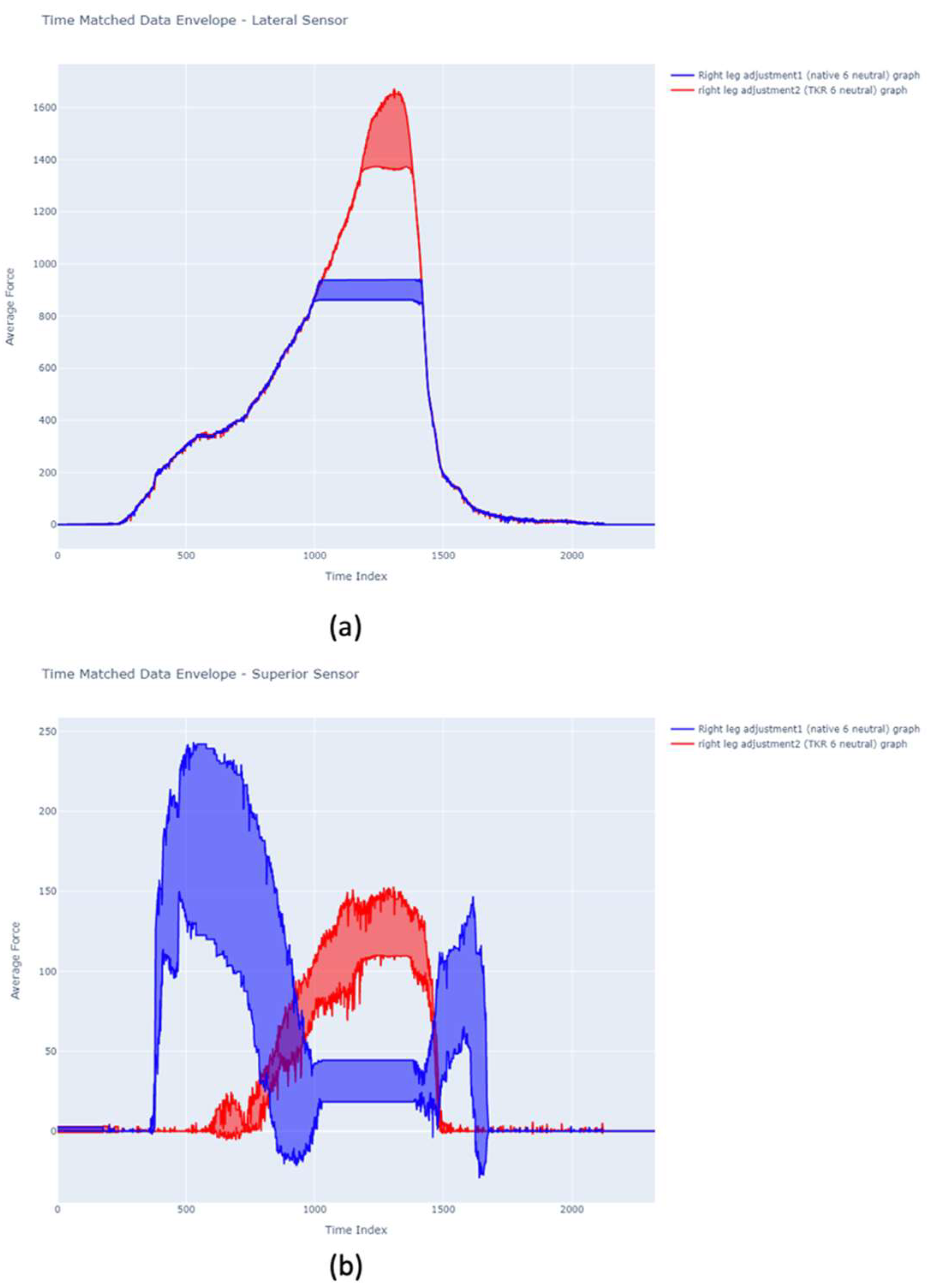
15]. The findings of this preliminary cadaveric study revealed that a novel force sensor device is capable of recording PFJ loads in four quadrants intraoperatively. No previously published studies have assessed the feasibility of utilizing this device, and we present findings validating its use in both a knee model and cadaveric specimen. Furthermore, we demonstrated how these measurements can guide surgical planning, with the ability to adjust the patella resection to achieve more physiologic, native loading and balance during TKR. Following assessment of the native PFJ loads in this study compared with TKR trial components in place, PFJ loads increased significantly with use of greater thickness adjustment shims. Angled adjustment shims revealed differential loads in the superior and lateral quadrant, which could guide adjustment cuts to “fine-tune” the preliminary patella using custom cutting guides with adjustable thickness and angles. Furthermore, we observed in our left knee study that performing an angled adjustment cut based on shim measurements could reproduce expected loads when re-measured with a neutral shim matched in resection thickness. Our study also observed the effects of under-stuffing or under-tensioning the patella, as uniformly reduced PFJ loads were measured after a large 4 mm adjustment cut was made in our right knee study.
PFJ loads increased significantly with greater shim thickness with TKR trial components in place compared to the native PFJ load measurements. Soft tissue tension in the extensor hood of the soft tissue structures surrounding the patella, quadriceps muscle and tendon, medial and lateral retinaculum and patella tendon, have been implicated in AKP [7]. Patella resection remains one of the least controlled aspects of TKR and it is widely acknowledged in the literature that improved surgical accuracy would reduce the risk of postoperative patella complications [16]. Amongst experienced surgeons, errors in patella resection occur in 10% of cases [17], with increased patellar resection angle reported to be the sole independent risk factor for AKP [18]. Inaccurate surgical patella resection, which is confounded by a lack of consensus, is responsible for a high incidence of patella-related complications, with some studies reporting that up to 80% of resurfaced patella are greater in size than their pre-surgical measurement with associated post-operative AKP [19]. “Over-stuffing” the PFJ through under-resection of the patella can lead to AKP following TKR [20]. While over-resection of the patella should be avoided due to the risk of fracture, [8] the quad sense device allowed for characterization of PFJ loads for comparison to the patient-specific native PFJ loads. This provides the surgeon with the ability to make adjustments in resection depth and angle of the patella resection, which could decrease the risk for patella under-resection and “over-stuffing”. Pre-operative alignment may also play a role in PFJ loads which are encountered. Notably, within the two cadaveric experiments conducted, we noted increased lateral PFJ loads. While the reason these lateral PFJ loads were observed is not immediately evident, this increase may be due to overall valgus alignment of the specimens, as lateral patella tracking was appreciable pre-operatively. Altered loads of the PFJ and extensor hood, even after an optimally implanted TKR may explain why patients rarely experience the “forgotten knee” [21].
Various methods for evaluating the quality of PFJ management following TKR have been studied, particularly to predict excessive PFJ loads and patellar maltracking which contribute to complications including anterior knee pain [12,13,14]. Q-angle, lateral patellar tilt, and patellar displacement have been measured in the post-operative or intraoperative setting to assess adequate patellar tracking [3,14]. An increase in Q-angle is associated with complications such as anterior knee pain following TKR, and this increase can be multifactorial occurring due to malrotated femoral or tibial components as well as an inadequately managed patella [3]. Lateral patellar tilt and patellar displacement, measured on a skyline axial radiograph, have also been implicated as important factors in patellar tracking, with lateral patellar tilt > 10° and patellar displacement > 3 mm associated with patellar maltracking [13,22]. Lateral patellar tilt and patellar displacement are determined by patellar resection angle, patellar component medialization, as well as positioning of the femoral component [14]. A prior study has also used surgical navigation systems to assess patellar tracking intraoperatively, as well as use of a force transducer to quantify patellofemoral contact pressures [23]. Compared to these prior techniques implemented to improve patellar tracking and reduce PFJ loads, none have implemented a technique where dynamic measurements are obtained intraoperatively to guide adjustment resection of the patella in a patient-specific fashion.
Patella maltracking occurring in the setting of too little tension or “under-tensioning” of the patella leads to reduced function and mechanical disadvantage as well [8]. Maltracking or malorientation of the extensor hood produces soft tissue pain and reduction in function as well as the prospect of increased wear in the patella resurfacing implant [9]. Important factors which contribute to patellar instability are component malposition. Oversized femoral components and/or its rotation are thought to cause patella tilting onto the trochlear grove, and resultant complications including AKP and instability. Rotation of the femoral component varies based on the alignment strategy used (mechanical or anatomical), with internal rotation of the femoral component demonstrated to correlate with poorer outcomes [15], and whilst less common, internal rotation of the tibial component, can cause increased strain on the PFJ. The quad sense allows characterization of loads in four quadrants of the patella that can alert the surgeon during trialing if non-physiologic forces in the lateral quadrant occur that can be related to femoral component malposition. Rotating platforms were hypothesized as a means of compensating for malrotation, although TKRs using these have shown no improved outcomes as compared to fixed bearing implants [24]. In the most recent designs of TKR, increased emphasis has been placed on a patella and soft tissue friendly design of the trochlea and on redesigns of the patella implant [25]. There is increasing focus on the amount of trochlea resection at TKR and the positioning and sizing of the femoral component, in addition to the establishment of the femoral implant accurately on the joint line [26]. While the importance of the extensor mechanism and reproduction of adequate PFJ loads appears to have received more attention, further clinical investigations are needed to assess whether the quad sense device can lead to improved patient functional outcomes.
The study we performed had several limitations. For one, the findings were limited by the use and number of cadaveric specimens. Native PFJ loading patterns were also obtained in knees with mild degenerative disease in the medial compartment, which cannot be generalizable as native loading patterns in healthy, non-painful knees. The technique we discuss may not provide a true assessment of native PFJ dynamic loading given these initial measurements were made in knees that were already arthritic. However, with traditional patella surgery techniques, no method for assessing PFJ loading exists, and this technique offers a considerable step forward. In particular, the measurement of “native”, patient-specific PFJ loading patterns prior to TKR cuts may allow for individualized adjustments of patella loading using the described device and workflow. While the diseased joint state must be taken into account when obtaining “native” PFJ loading patterns, no other strategies to make intraoperative adjustments have been proposed and developed. Currently, surgeons rely on reproducing the measured thickness of the native patella and substitute a polyethylene implant with the assumption that this will reproduce PFJ loading. The results of this study show this is conclusively not the case, and in every example, PFJ loading is significantly altered by TKR with patella resurfacing carried out with this method. Comparatively, this technique actually offers real-time evaluation of PFJ loading, such that the resurfaced patella can be adjusted as needed in response to observed PFJ loads. Gaining data on the abnormal loading forces following TKR using this method will allow the surgeon to alter the patella resection to address these changes. Abnormal tissue loading has been shown to relate strongly to extensor hood pain and function [12,13,14], and further evaluations of native PFJ loading without degenerative disease may be needed to establish true normal PFJ loading patterns.
Additional limitations included that PFJ force measurements were time based and not associated with knee flexion angle during range of motion trials. However, all knee range of motion trials were performed by the senior author and were consistent throughout the study. During range of motion trials, the arthrotomy performed was provisionally closed with two towel clamps approximating the superior pole of the patella and medial retinaculum, which were marked prior to incision with a skin marker. Under these circumstances, PFJ loads were measured. However, even small changes in arthrotomy closure positioning may have an effect on patella tracking which can differ from the loads measured during these intraoperative trials [27]. While the time warp function was used to fit knee flexion angles to load measurements, future investigations and iterations of the device may include flexion angle measurements associated with PFJ loads. Patella resection adjustments were made based on evaluation of PFJ loading characteristics with different thickness shim and angles by the senior author.
In summary, the method detailed in our study for evaluation of PFJ loads presents a technique for improving management of patella resection and could be easily incorporated into the existing work flow of TKR. A planned work flow would involve first performing a patella resection and then obtaining native PFJ loads. Subsequently, evaluation of PFJ load after TKR was performed, as well as the effect of a potential secondary patella resection. A secondary patella resection might then be required to normalize loading of the PFJ. Based on the cadaveric experience, this might add 4–5 min to the procedure but does not require extra steps in the knee procedure and therefore will not materially add to the risk associated with the operation. Significant benefit in outcomes would accrue if PFJ loading forces can be normalized with this proposed method. Future studies will evaluate the use of pattern recognition algorithms to help surgeons identify PFJ loading patterns and to make choices on appropriate adjustment cuts intraoperatively. Furthermore, expanding to measure PFJ loads in a larger sample size, as well as in non-arthritic knees, will provide surgeons with a better representative understanding of what optimal PFJ load patterns should be achieved based on healthy native knees.

5. Conclusions

The quad sense device was able to record PFJ loading before and after TKR resections and compare PFJ loading characteristics in multiple patella quadrants. This allowed for the adjustment of the thickness and angle of the patella resection to reproduce patient-specific PFJ loading. Altering patella resection depth and angles subsequently may allow extensor mechanism loading in TKR to approach that of the native knee. This novel, patient-specific approach to patella resurfacing acknowledges the importance of the PFJ and extensor mechanism as the main contributor to knee function. Further in vitro and in vivo studies of this novel device are needed to reveal its efficacy and safety in potentially decreasing PFJ complications and AKP in TKR and ultimately improving patient reported outcomes.

Author Contributions

Conceptualization, D.B. and J.F.P.; methodology, A.B., D.B. and J.F.P.; software, A.W. and S.N.; validation, A.B., D.B., A.W. and J.F.P.; formal analysis, A.B., A.W. and S.N.; investigation, A.W., D.B., M.F.G. and J.F.P.; resources, A.W. and J.F.P.; data curation, A.W., S.N. and M.F.G.; writing—original draft preparation, A.B. and M.F.G.; writing—review and editing, D.B. and J.F.P.; visualization, A.W., M.F.G. and S.N; supervision, D.B. and J.F.P.; project administration, D.B. and J.F.P.; funding acquisition, J.F.P. All authors have read and agreed to the published version of the manuscript.

Funding

This research received no external funding.

Institutional Review Board Statement

Ethical approval from the University of Pittsburgh’s Committee for Oversight of Research and Clinical Training involving Decedents (CORID 1159) was obtained for this study, and the two cadaveric specimens utilized in this study were procured from institution-approved tissue suppliers. Institutional Review Board approval was not required.

Informed Consent Statement

Not applicable.

Data Availability Statement

The data presented in this study are held and accessible on request from Eventum Orthopaedics. Data are not publicly available due to privacy concerns and are available on request from the corresponding author.

Acknowledgments

The authors thank Smith & Nephew for providing TKR instrumentation and trials. The authors thank the personnel of the University of Pittsburgh Anatomy Lab for their assistance with this study.

Conflicts of Interest

The following authors listed below have the possible conflicts of interest to declare: Annabel Watson is an employee of Eventum Orthopaedics Ltd. David Barrett, Susie Naybour, and F. Johannes Plate are minority shareholders of Eventum Orthopaedics Ltd. All authors certify that this investigation was performed in conformity with ethical principles of research.

Appendix A

Table A1. Comparison of mean maximal load (N) recorded using neutral shims before and after 4 mm adjustment cut performed on the right TKR in Specimen 1, analysed via one-way ANOVA.
Quadrant6 mm Neutral7 mm Neutral8 mm Neutral9 mm Neutralp-Value
Pre-CutPost-CutPre-CutPost-CutPre-cutPost-CutPre-CutPost-Cut
Medial:0.3 ± 0.10.3 ± 0.00.4 ± 0.10.4 ± 0.10.3 ± 0.00.3 ± 0.00.3 ± 0.00.3 ± 0.10.52
Lateral:79.2 ± 12.911.5 ± 2.081.8 ± 11.613.5 ± 1.283.9 ± 12.919.3 ± 1.7105.7 ± 8.020.8 ± 1.9<0.01 *
Superior:7.0 ± 1.52.7 ± 0.711.6 ± 1.65.8 ± 1.011.6 ± 1.910.4 ± 0.913.5 ± 0.614.1 ± 1.7<0.01 *
Inferior:0.2 ± 0.00.2 ± 0.10.2 ± 0.00.2 ± 0.00.2 ± 0.00.2 ± 0.00.2 ± 0.00.2 ± 0.00.56
* denotes statistical significance.

References

  1. Scott, C.E.H.; Howie, C.R.; MacDonald, D.; Biant, L.C. Predicting dissatisfaction following total knee replacement: A prospective study of 1217 patients. J. Bone Jt. Surg. Br. 2010, 92, 1253–1258. [Google Scholar] [CrossRef] [PubMed]
  2. Ben-Shlomo, Y.; Blom, A.; Boulton, C.; Brittain, R.; Clark, E.; Craig, R.; Dawson-Bowling, S.; Deere, K.; Esler, C.; Espinoza, O.; et al. The National Joint Registry 17th Annual Report; National Joint Registry: London, UK, 2020. [Google Scholar]
  3. Shervin, D.; Pratt, K.; Healey, T.; Nguyen, S.; Mihalko, W.M.; El-Othmani, M.M.; Saleh, K.J. Anterior knee pain following primary total knee arthroplasty. World J. Orthop. 2015, 6, 795–803. [Google Scholar] [CrossRef] [PubMed]
  4. Khan, M.; Osman, K.; Green, G.; Haddad, F.S. The epidemiology of failure in total knee arthroplasty: Avoiding your next revision. Bone Joint J. 2016, 98-B, 105–112. [Google Scholar] [CrossRef] [PubMed] [Green Version]
  5. Petersen, W.; Rembitzki, I.V.; Brüggemann, G.-P.; Ellermann, A.; Best, R.; Koppenburg, A.G.; Liebau, C. Anterior knee pain after total knee arthroplasty: A narrative review. Int. Orthop. 2013, 38, 319–328. [Google Scholar] [CrossRef] [Green Version]
  6. Scuderi, G.R.; Insall, J.N.; Scott, N.W. Patellofemoral pain after total knee arthroplasty. J. Am. Acad. Orthop. Surg. 1994, 2, 239–246. [Google Scholar] [CrossRef]
  7. Ghosh, K.M.; Merican, A.M.; Iranpour, F.; Deehan, D.J.; Amis, A.A. The effect of overstuffing the patellofemoral joint on the extensor retinaculum of the knee. Knee. Surg. Sports Traumatol. Arthrosc. 2009, 17, 1211–1216. [Google Scholar] [CrossRef]
  8. Fitzpatrick, C.K.; Kim, R.H.; Ali, A.A.; Smoger, L.M.; Rullkoetter, P.J. Effects of resection thickness on mechanics of resurfaced patellae. J. Biomech. 2013, 46, 1568–1575. [Google Scholar] [CrossRef]
  9. Kim, J.H.; Yoo, B.-W.; Kim, A.C.-W. Influence of the rotational alignment of the femoral and patellar components on patellar tilt in total knee arthroplasty. Knee Surg. Relat. Res. 2015, 27, 163–167. [Google Scholar] [CrossRef] [Green Version]
  10. Mannen, E.M.; Ali, A.A.; Dennis, D.A.; Haas, B.D.; Rullkoetter, P.J.; Shelburne, K.B. Influence of Component Geometry on Patellar Mechanics in Posterior-Stabilized Rotating Platform Total Knee Arthroplasty. J. Arthroplast. 2019, 34, 974–980. [Google Scholar] [CrossRef]
  11. Ali, A.A.; Mannen, E.M.; Rullkoetter, P.J.; Shelburne, K.B. In vivo comparison of medialized dome and anatomic patellofemoral geometries using subject-specific computational modeling. J. Orthop. Res. 2018, 36, 1910–1918. [Google Scholar] [CrossRef]
  12. Emami, M.; Ghahramani, M.-H.; Abdinejad, F.; Namazi, H. Q-angle: An invaluable parameter for evaluation of anterior knee pain. Arch. Iran. Med. 2007, 10, 24–26. [Google Scholar]
  13. Noh, J.H.; Kim, N.Y.; Song, K.I. Intraoperative patellar maltracking and postoperative radiographic patellar malalignment were more frequent in cases of complete medial collateral ligament release in cruciate-retaining total knee arthroplasty. Knee Surg. Relat. Res. 2021, 33, 9. [Google Scholar] [CrossRef] [PubMed]
  14. Anglin, C.; Brimacombe, J.; Hodgson, A.; Masri, B.; Greidanus, N.; Tonetti, J.; Wilson, D. Determinants of patellar tracking in total knee arthroplasty. Clin. Biomech. 2008, 23, 900–910. [Google Scholar] [CrossRef] [PubMed]
  15. Longo, U.G.; Ciuffreda, M.; Mannering, N.; D’Andrea, V.; Cimmino, M.; Denaro, V. Patellar Resurfacing in Total Knee Arthroplasty: Systematic Review and Meta-Analysis. J. Arthroplast. 2018, 33, 620–632. [Google Scholar] [CrossRef] [PubMed]
  16. Heo, S.M.; Harris, I.; Naylor, J.; Lewin, A.M. Complications to 6 months following total hip or knee arthroplasty: Observations from an Australian clinical outcomes registry. BMC Musculoskelet. Disord. 2020, 21, 602. [Google Scholar] [CrossRef] [PubMed]
  17. Rex, E.L.; Gaudelli, C.; Illical, E.M.; Person, J.; Arlt, K.C.T.; Wylant, B.; Anglin, C. Guiding device for the patellar cut in total knee arthroplasty: Design and validation. Bioengineering 2018, 5, 38. [Google Scholar] [CrossRef] [Green Version]
  18. White, P.B.; Sharma, M.; Siddiqi, A.; Satalich, J.R.; Ranawat, A.S.; Ranawat, C.S. Role of anatomical patella replacement on anterior knee pain. J. Arthroplast. 2019, 34, 887–892. [Google Scholar] [CrossRef]
  19. Ledger, M.; Shakespeare, D.; Scaddan, M. Accuracy of patellar resection in total knee replacement: A study using the medial pivot knee. Knee. 2005, 12, 13–19. [Google Scholar] [CrossRef]
  20. Xie, X. Effect of Patellar Component Thickness on Patellar Kinematics and Patellofemoral Joint Function Following Total Knee Replacement. Ph.D. Thesis, Clemson University, Clemson, SC, USA, 1 August 2014. [Google Scholar]
  21. Ranawat, A.S.; Ranawat, C.S.; White, P.B. Fixed Bearings versus Rotating Platforms in Total Knee Arthroplasty. J. Knee Surg. 2015, 28, 358–362. [Google Scholar] [CrossRef]
  22. Heesterbeek, P.; Beumers, M.; Jacobs, W.; Havinga, M.; Wymenga, A. A comparison of reproducibility of measurement techniques for patella position on axial radiographs after total knee arthroplasty. Knee 2007, 14, 411–416. [Google Scholar] [CrossRef]
  23. Konno, T.; Onodera, T.; Nishio, Y.; Kasahara, Y.; Iwasaki, N.; Majima, T. Correlation between knee kinematics and patellofemoral contact pressure in total knee arthroplasty. J. Arthroplast. 2014, 29, 2305–2308. [Google Scholar] [CrossRef] [PubMed]
  24. Clement, N.D.; Bardgett, M.; Weir, D.; Holland, J.; Gerrand, C.; Deehan, D. Three groups of dissatisfied patients exist after total knee arthroplasty: Early, persistent and late. Bone Jt. J. 2018, 100-B, 161–169. [Google Scholar] [CrossRef] [PubMed]
  25. Kim, S.J.; Bamne, A.; Song, Y.D.; Kang, Y.G.; Kim, A.T.K. Patients still wish for key improvements after total knee arthroplasty. Knee Surg. Relat. Res. 2015, 27, 24–33. [Google Scholar] [CrossRef] [PubMed]
  26. Wang, Z.; Wen, L.; Zhang, L.; Ma, D.; Dong, X.; Qu, T. Undercoverage of lateral trochlear resection is correlated with the tibiofemoral alignment parameters in kinematically aligned TKA: A retrospective clinical study. BMC Musculoskelet. Disord. 2021, 22, 196. [Google Scholar] [CrossRef]
  27. Plate, J.F.; Seyler, T.M.; Halvorson, J.J.; Santago, A.C.; Lang, J.E. Non-anatomical capsular closure of a standard parapatellar knee arthrotomy leads to patellar maltracking and decreased range of motion: A cadaver study. Knee Surg. Sports Traumatol. Arthrosc. 2013, 22, 543–549. [Google Scholar] [CrossRef]
Figure 1. Quad sense force sensor. (a) 6 mm neutral shim applied to the sensor paddle. Each circle corresponds to one of four quadrants containing a separate sensor (Medial, Lateral, Superior, Inferior). (b) Tines on the undersurface of the sensor paddle are used to attach the sensor to the resected patella to hold it in place during range of motion trials.
Applsci 12 10584 g001
Figure 2. Demonstration of application of quad sense force sensor. (a) Placement of the quad sense sensor along undersurface of everted patella. Position of the sensor paddle is marked with electrocautery or a skin marker. (b) View of the quad sense sensor positioning during trialing with the patella reduced. Two towel clips are used for provisional reduction and closure of the extensor mechanism during range of motion trialing.
Applsci 12 10584 g002
Figure 3. CAD layout of the scanned femoral and tibial components, altered to be compatible with the Medical Model Left Cadaver Leg set-up when 3D printed and utilized for the in vitro experiment.
Applsci 12 10584 g003
Figure 4. Surgical technique for performing initial patella cut. Patellar clamp with attached 6 mm custom cutting guide is applied to the patella, and resection is performed with a standard oscillating saw.
Applsci 12 10584 g004
Figure 5. Flow diagram demonstrating planned steps of the cadaveric study, including when PFJ load measurements were obtained at key timepoints during the TKR procedure.
Applsci 12 10584 g005
Figure 6. Technique is shown for performing an adjustment cut to the manual left TKR set at 3 mm with a 2.5° inferiorly angled orientation guide. (a) Patellar clamp and custom adjustment cutting guide set. (b) Adjustment cut performed with patellar clamp and custom guide for a 3 mm 2.5° inferiorly angled cut in place. (c) Resected patella is shown after adjustment cut is completed.
Applsci 12 10584 g006
Figure 7. Graph of dynamic time warping analysis performed for the superior sensor load measurements obtained in an in vitro experiment using a model knee. Trials performed for the 6 mm to 9 mm neutral shims were consolidated and standardized by time, demonstrating the increase in measured force observed with each incremental increase in shim size. Purple = 6 mm neutral shim, Blue = 7 mm neutral shim, Green = 8 mm neutral shim, Red = 9 mm neutral shim. X-axis denotes Time Index (total of 12 s), and Y-axis denotes Average Force (in mV).
Applsci 12 10584 g007
Figure 8. Graph of dynamic time warping analysis performed for the medial sensor load measurements obtained in an in vitro experiment using a model knee. Trials performed for the 6 mm 2.5° angled shims were consolidated and standardized by time, demonstrating the changes in measured force based on shim angle orientation. Red = 6 mm neutral shim, Green = 6 mm 2.5° medial angle shim, Blue = 6 mm 2.5° lateral angle shim. X-axis denotes Time Index (total of 12 s), and Y-axis denotes Average Force (in mV).
Applsci 12 10584 g008
Figure 9. Comparison of visual graphs generated for PFJ load obtained before and after TKR in the right knee of Specimen 1. Three peaks seen correspond to the three knee flexion-extension cycles obtained in a 12 s recording period. Green = Medial sensor; Red = Lateral; Blue = Superior; Orange = Inferior. (a) PFJ load measured in native (natural) right knee with 6 mm neutral shim. (b) PFJ load measured in right knee with trial TKR components in place with 6 mm neutral shim. * Note: X-axis delineates time (total of 12 s) in which the three flexion-extension trials were performed. Y-axis (in mV) has different scales generated: (a) 2000 units of load (b) 2400 units of load.
Applsci 12 10584 g009
Figure 10. Graph of dynamic time warping analysis performed comparing the native and TKR load measurement in the right knee of Specimen 1. (a) Graph for lateral sensor loads measured in the right knee. Blue = Native 6 mm neutral shim; Red = TKR 6 mm neutral shim. (b) Graph for superior sensor loads measured in the right knee. Blue = Native 6 mm neutral shim; Red = TKR 6 mm neutral shim. X-axis denotes Time Index (total of 12 s), and Y-axis denotes Average Force (in mV).
Applsci 12 10584 g010
Table 1. Baseline mean maximal load measurements (N) and standard deviation recorded in native knees with the 6 mm neutral shim.
QuadrantCombined KneesSpecimen 1Specimen 2
Medial9.2 ± 11.60.6 ± 0.817.8 ± 10.9
Lateral28.8 ± 13.040.6 ± 5.017.0 ± 3.9
Superior6.4 ± 5.611.5 ± 1.71.3 ± 1.4
Inferior1.0 ± 1.00.2 ± 0.01.8 ± 0.9
Table 2. Comparison of mean maximal load (N) and standard deviation for all four knees between native trial and TKR trial with the 6 mm neutral shim, compared via paired t-test.
QuadrantNativeTKRp-Value
Medial9.2 ± 11.60.6 ± 0.60.021 *
Lateral28.8 ± 13.038.5 ± 26.70.139
Superior6.4 ± 5.63.0 ± 2.90.011 *
Inferior1.0 ± 1.02.0 ± 2.70.178
* denotes statistical significance.
Table 3. Comparison of mean maximal load (N) and standard deviation of measurements obtained in the TKR trials for different thickness neutral shims in all four knees, analyzed via two-way ANOVA with multiple comparisons.
Quadrant6 mm Neutral7 mm Neutral8 mm Neutral9 mm Neutralp-Value
Medial:0.6 ± 0.613.0 ± 22.914.1 ± 23.82.8 ± 3.6<0.001 *
Lateral:38.5 ± 26.742.6 ± 25.647.0 ± 29.867.5 ± 40.6<0.001 *
Superior:3.0 ± 2.97.5 ± 4.67.5 ± 5.49.6 ± 6.3<0.001 *
Inferior:2.0 ± 2.71.6 ± 1.83.8 ± 4.33.9 ± 4.10.004 *
* denotes statistical significance.
Table 4. Comparison of mean maximal load (N) and standard deviation measurements by quadrant obtained in the TKR trials for different orientations of the 6 mm 2.5° angle shim for all four knees, analyzed via two-way ANOVA with multiple comparisons.
QuadrantMedial OrientationLateral OrientationSuperior OrientationInferior Orientationp-Value
Medial:2.6 ± 3.42.5 ± 3.812.7 ± 22.28.9 ± 8.6<0.001 *
Lateral:24.7 ± 11.126.5 ± 9.125.2 ±14.125.4 ± 15.1<0.001 *
Superior:2.7 ± 4.02.8 ± 1.83.0 ± 2.61.6 ± 2.0<0.001 *
Inferior:2.2 ± 3.00.8 ± 1.00.7 ± 0.71.6 ± 2.0<0.001 *
* denotes statistical significance.
Table 5. Comparison of mean maximal load (N) and standard deviation recorded prior to making a planned adjustment cut (n = 3: Left knee of Specimen 1; both knees of Specimen 2) compared to the post-adjustment cut measurement obtained using 9 mm neutral shim. Analyzed via paired t-test.
QuadrantPre-CutPost-Cutp-Value
Medial:13.3 ± 15.315.4 ± 13.00.281
Lateral:33.5 ± 15.715.7 ± 9.70.002 *
Superior:7.6 ± 9.310.5 ± 2.90.249
Inferior:2.5 ± 2.24.9 ± 3.60.031 *
* denotes statistical significance.
Publisher’s Note: MDPI stays neutral with regard to jurisdictional claims in published maps and institutional affiliations.

