Article

Development, Research, Optimization and Experiment of Exoskeleton Robot for Hand Rehabilitation Training

1
School of Biomedical Engineering (Suzhou), Division of Life Sciences and Medicine, University of Science and Technology of China, Hefei 230026, China
2
Suzhou Institute of Biomedical Engineering and Technology, Chinese Academy of Sciences, Suzhou 215163, China
3
School of Mechanical and Electrical Engineering, Changchun University of Science and Technology, Changchun 130001, China
*
Author to whom correspondence should be addressed.
Appl. Sci. 2022, 12(20), 10580; https://doi.org/10.3390/app122010580
Submission received: 30 September 2022 / Revised: 11 October 2022 / Accepted: 17 October 2022 / Published: 20 October 2022
(This article belongs to the Special Issue Micro-Medical Robotics Research)

Abstract

:
As one of the most influential symptoms of daily life after stroke, hand dysfunction has seriously affected the quality of life of patients and families. At present, the commonly used rehabilitation method is to carry out continuous passive training on the patient’s fingers with the help of physical therapists, so as to promote the rehabilitation of the hands. However, this kind of therapist-assisted rehabilitation greatly increases the cost of rehabilitation treatment and is not conducive to the promotion of household use. Many exoskeleton hand rehabilitation robots still lack in overall weight and control, resulting in the application potential of exoskeleton hand rehabilitation robots not being fully developed, and the commercial and clinical success cases are limited. The research of this paper focuses on the structural design and electronic control design of the exoskeleton hand rehabilitation robot. Through the design of an exoskeleton hand rehabilitation robot suitable for human hands, the kinematics parameters are obtained by kinematics simulation, and the lightweight design of the hand rehabilitation robot is completed by using topology optimization. At the same time, this paper shows the development technology of the rehabilitation robot control system. We hope that through the subsequent product development, the exoskeleton hand rehabilitation robot studied in this paper can be applied in the future.

1. Introduction

The hand is one of the most complex motion and sensory organs of human body. A single hand has 24 degrees of freedom, and the finger part alone has 21 degrees of freedom. Therefore, the movement pattern of the finger is very complex and can complete many delicate movements [1,2].
However, the function of the human hand will deteriorate due to bone diseases, hand injuries, nerve injuries and other reasons. Among many diseases, stroke can cause a variety of neurological damage to patients, and it is a major factor leading to the impairment of hand function [3,4,5].
In recent years, with the continuous development of medical technology, the death rate of stroke has gradually decreased. However, stroke still has a very high disability rate and has a great impact on life. Among the survivors of stroke, about 80~90% of the patients will leave limb motor function defects and lose the ability to live independently and exercise [6,7].
In China, the number of new stroke patients is more than 2 million every year. With the change of social and demographic structure in China, the aging problem is further aggravated. It is expected that the number of stroke patients will rise further in the long future. Motor dysfunction after stroke has become one of the hotspots of modern rehabilitation medicine [8,9].
For the motor dysfunction caused by stroke, the clinical rehabilitation treatment is mainly to remodel the damaged nerve. Generally, the therapist exercises the patient’s limbs and muscles to promote the body’s learning and improve the damaged nerves through repeated movements of the limbs. Traditionally, patients go to rehabilitation institutions to assist rehabilitation training through professional physiotherapists to assist patients to complete a series of physiotherapy exercises to achieve the goal of functional rehabilitation. However, this method is not very effective. Many patients cannot rely on rehabilitation training because of its high cost and time-consuming labor [10].
To solve this problem, the rehabilitation robot has many advantages, such as repetitive work, not limited by time and place. Therefore, the rehabilitation robot that assists limb movement rehabilitation has become a research hotspot at home and abroad.
The hand functional rehabilitation robot is an important limb rehabilitation device. Its main task is to assist the hand joints and fingers to complete the rehabilitation actions of bending and stretching. Additionally, the patient can complete the continuous passive exercise therapy provided by the doctor.
Research on the hand exoskeleton began in the 1990s and the hand exoskeleton developed from the industrial manipulator.
Nicola Secciani et al. (Department of Industrial Engineering, University of Florence) developed portable, wearable and highly customizable hand exoskeletons to assist patients with hand disabilities, and defines a patient-centered design strategy to tailor the device to the needs of different users [11]. Lightweight underactuated RACA neurorehabilitation exoskeleton designed and characterized by Victor Moreno-SanJuan (Institute of Advanced Production Technology, University of Valladolid) [12]. Mine Sarac (Frisoli PERCRO Lab) proposed an underactuated hand exoskeleton that adapts to the shape and size of objects during grasping tasks [13].
A two-finger exoskeleton with force feedback for the teleoperation of mobile robots was designed by Manuel Arias-Montiel et al. (Institute of Electronics and Mechatronics, Mistka University of Technology) for the human hand, and it does not limit the range of motion of the human hand, nor does it have any mechanical interference between the exoskeleton and the user’s fingers [14].
Eric M. Refour (Virginia Tech Department of Mechanical Engineering) proposes a novel, thin, and lightweight hand exoskeleton linkage with force control enabled by compact tandem elastic actuators [15]. Giuseppe Carbone (University of Calabria) presents a systematic design approach for a novel dual-DOF actuated linkage for motion-assisted finger exoskeletons [16]. Marco Ceccarelli (Laboratory of Robotic Mechatronics, Department of Industrial Engineering, University of Tovergata) describes a finger exoskeleton with a prototype of the ExoFinger, the experiments describe the proper operation of the ExoFinger. In addition, the skeleton has various functions for motion control and medical monitoring sensors [17].
Nuevo Leon developed a wearable finger exoskeleton, motion transmission is based on a linkage mechanism that allows the possibility of coupled phalanx movements, thus using only one active degree of freedom, one linear for each finger drive, meaning that you can achieve the natural movement of the hand [18]. Husam Almusawi (Faculty of Information, University of Debrecen) designed and developed a novel cost-effective mechatronic system for continuous passive motion training of fingers and wrists [19]. Anirban Chowdhury (Department of Mechanical Engineering, Indian Institute of Technology) proposed a stroke rehabilitation hand exoskeleton with flexible structure and control, and verified its potential clinical effectiveness through preliminary clinical trials in stroke patients [20].
Uikyum Kim et al. (Department of Mechanical Engineering, Asia University) developed a dexterous anthropomorphic robotic hand with integrated linkage actuation. The mechanism is constructed through a fusion of parallel and series mechanisms to achieve two-DOF motion in the metacarpophalangeal joint and single-DOF motion in the proximal interphalangeal joint through a link combination [21]. Teja Vanteddu (Department of Mechanical Engineering at Virginia Tech) designed a robotic exoskeleton glove for stable grip control [22]. Jenny Carolina Castiblanco (University of Pontificia) has solved the problem of how to provide active support through a robot-assisted exoskeleton, by developing a new closed-loop structure that continuously measures electromyographic signals (EMG) to adjust the assistance provided by the exoskeleton [23].
Ouyang Kun (Southern Taiwan University of Science and Technology) designed an exoskeleton assistive device to help hemiplegic stroke patients stretch their fingers and open their palms to simulate the effect of rehabilitation [24]. Inseong Jo (Department of Mechanical Engineering) developed a portable and spring-guided hand exoskeleton system for exercising finger flexion and extension [25].
Zhang Fuhai from the State Key Laboratory of Robotics and Systems, Harbin Institute of Technology, designed an active and passive control system for the exoskeleton rehabilitation hand, which can adapt to fingers of different thicknesses and lengths to prevent secondary injuries [26]. Li Min (School of Mechanical Engineering, Xi’an Jiaotong University) designed an attention-controlled finger extension and flexion rehabilitation hand based on a rigid-flexible combined mechanism. Due to the design and characteristics of its new multi-segment mechanism driven by steel springs, it can help the fingers to stretch and curve [27]. Cheng Chang (Institute of Automation, Chinese Academy of Sciences) proposed a novel controller for finger position detection and tracking control of a wearable hand rehabilitation robot [28]. Li Ke (Laboratory of Rehabilitation Engineering, School of Control Science and Engineering, Shandong University) designed a wearable robotic hand exoskeleton based on surface EMG signals, which has greater freedom of movement, greater range of joint motion, and can be freely controlled according to motion intentions [29]. Zhiyuan Lu (Department of Physical Medicine and Rehabilitation, University of Texas Health Science Center at Houston) developed an intent-driven hand training system using sEMG as intention recognition device [30].
The hand functional rehabilitation training devices and exoskeleton devices developed by different research institutions have different structures and driving modes. The main structure of a hand rehabilitation robot includes linkage mechanism, micro cylinder mechanism, cable drive mechanism, gear mechanism, flexible mechanism, and so on.
Through mechanical design, the hand rehabilitation robot can achieve the synchronous hand movement requirements, thus achieving the rehabilitation training effect. The motion accuracy, bionics and portability of the structure are particularly important.

2. Materials and Methods

2.1. Design of Hand Function Rehabilitation Robot

2.1.1. Hand Structure and Structure Design of Rehabilitation Robot

Hand dysfunction is one of the most common dysfunctions in stroke patients. It is one of the main factors hindering patients’ normal life, work and social life, as well as returning to family and society, causing a heavy burden on patients and families. The function of the hand is complex, including many functions such as movement and sensation, and is also closely related to the advanced functions of the brain such as cognition. Its movement has the characteristics of a large range of activities and complex and diverse forms of movement. It is the most important effector organ of purposeful and instrumental movement [31,32].
Of the 206 bones in the human body, 54 are in the hand, equivalent to a quarter of the total number of human bones; The muscle structures that drive them are also extremely complex. At the same time, the joints of fingers have more degrees of freedom and various motion functions. In order to use robots to realize these functions, many dexterous anthropomorphic robot hands have been developed. In order to perform an effective grasping action, many effective manipulators with adaptive grasping or low degree of freedom (DOF) have been developed [33,34,35].
In different existing architectures, we decided to adopt the exoskeleton based on connecting rod coupling linkage. The connecting rod driving mechanisms have inherent advantages, such as ruggedness, easy manufacture and maintenance; however, they also have disadvantages, such as the difficulty in carrying out multi-degree of freedom motions in a small space while maintaining sufficient workspace. Therefore, it is of great significance to realize a linkage-driven robot finger mechanism with human-like finger motions.
The motion transmission is based on the linkage mechanism to realize the coupling motion of each joint of the finger. The rod can transmit tensile and compressive loads. Therefore, each finger can only use one degree of freedom, that is, it can perform the extension (the most needed motion in rehabilitation) and flexion (auxiliary) motion of the finger.
Specifically, the designed exoskeleton rehabilitation robot is mainly composed of four identical finger modules, which drive the index finger, middle finger, ring finger and little finger, respectively. Each finger module has a degree of freedom actively driven by a linear driver.
The structural design drawing is shown in Figure 1. The linear driver is constrained on the fixed frame and connected with the proximal phalanx fixed block of the finger. When the driver moves in a straight line, it drives the proximal phalanx fixed block of the finger to move around the circular guide rail with the shaft, and then drives the connecting rod to move. The load transmitted by the connecting rod drives the middle phalanx fixed block to move along the circular guide rail, so as to drive the middle phalanx fixed block to move, realizing the bending action of the finger. Similarly, the linear driver moves in the opposite direction to complete the extension movement of the finger.

2.1.2. Design of Control Hardware

The control system of hand functional rehabilitation robot is mainly com-posed of main chip, power supply, WIFI, touch screen, actuator control module, etc. The control system is shown in Figure 2.
We used linear actuators produced in a Canadian company called Actuonix Motion Devices, as shown in Figure 3, which has an onboard software-based digital microcontroller. Although this actuator we used in the hand robot contains a built-in control board, the control board is used to receive control signals and feedback position, the microcontroller is not user-programmable.
We use the four pins in the signal interface of the linear actuator for control and feedback. They are ground terminal, power supply terminal, control signal input terminal, and position feedback signal terminal.
Two of the pins GND and +6 V are used to supply power to the linear actuator. The control signal input pin can receive a 0–5 V voltage signal or a 5 V PWM signal to control the stroke of the linear actuator from 0–100%. We used a 5 Volt 1 kHz square wave on actuator control. In this case, the duty cycle of the control input is the same as the stroke ratio. The position feedback signal pin linearly outputs a voltage signal of 0–3.3 V, according to the actual position ratio of the linear actuator.
The drive interface of each linear actuator uses the four-pin interface of xh254. The interface includes grounding, 6 V power supply, linear actuator control terminal and linear motor position detection.
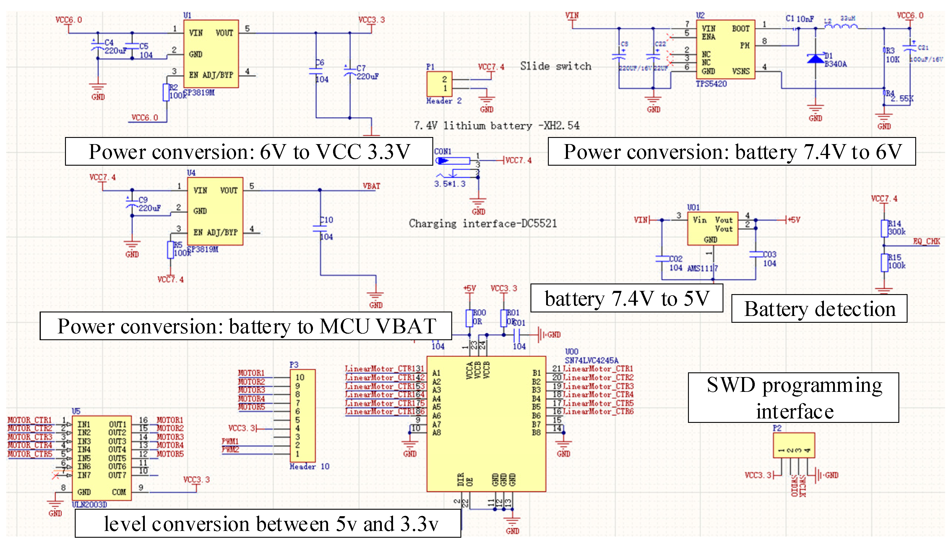
The power supply of the screen in the system is 5 V, the driving voltage of the linear actuator is 6 V, and the voltage of the single chip microcomputer system is 3.3 V. Therefore, in this paper, the hardware system selects 7.4 V power supply and provides different voltages through different DC–DC and linear converters step-down systems. Figure 4 shows the power supply and DC–DC step-down system. Different power chips are used to realize the power supply of 3.3 V, 5 V and 6 V. At the same time, because the PWM control signal voltage provided by the single chip microcomputer is 3.3 V, which is inconsistent with the driving requirements of the linear actuator, sn74lvc4245a of “octal bus translator and 3.3 V to 5 V shifter with 3-state outputs” is used to regulate the PWM control signal in this paper.
Stm32f405 chip is used for the main control of the hand function robot, as shown in Figure 5.
Figure 4 and Figure 5 show the hardware design of the rehabilitation robot. In the schematic part, the placement direction or labeling of some devices is not standardized.
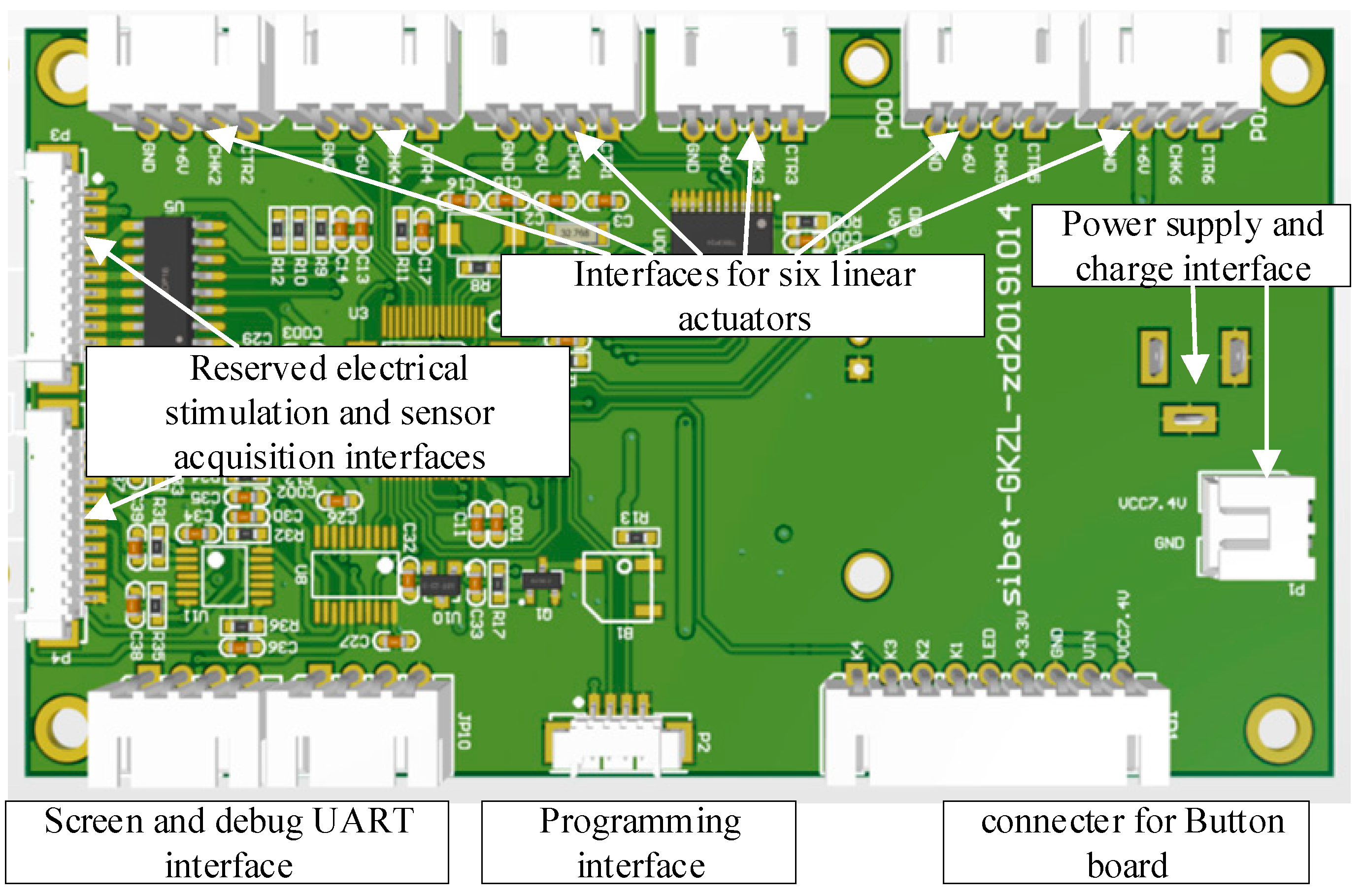
Figure 6 shows the main control circuit board of the exoskeleton hand rehabilitation robot. Xh2 is used for motor control interface, UART screen interface, UART debugging interface and battery interface. MX1 is used for program debugging and sensor interface.

2.1.3. Rehabilitation Training Model and Software

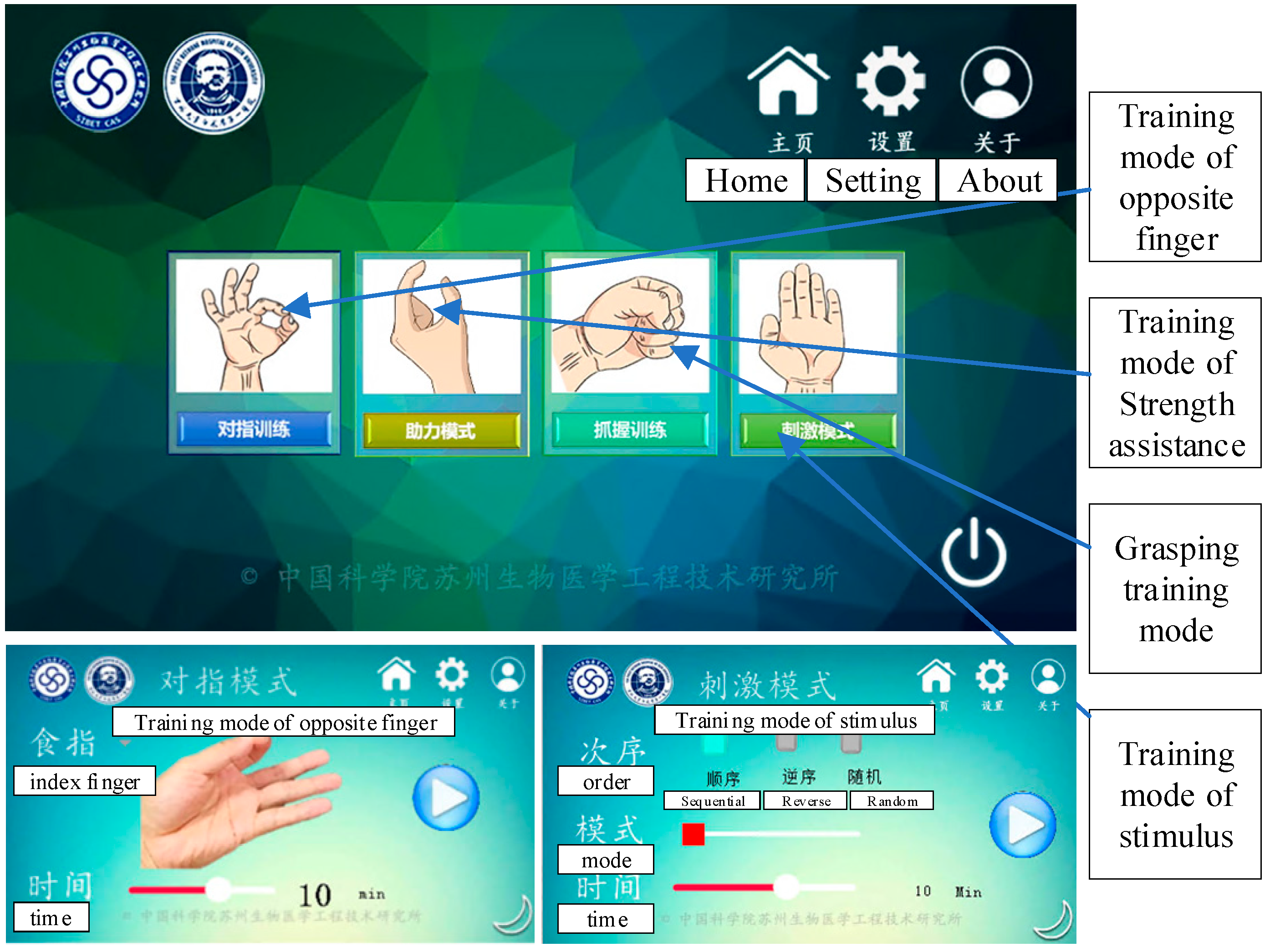
Four modes are designed for the hand functional rehabilitation robot, including finger training, assistance training, grasping training and stimulation mode. In the daily rehabilitation training, the most important ones are finger training and grip training. Our software interface is shown in Figure 7.
In the software interface as shown in Figure 7, there are four training modes: pinch two fingers, strength assistance, grasping training, and stimulus mode.
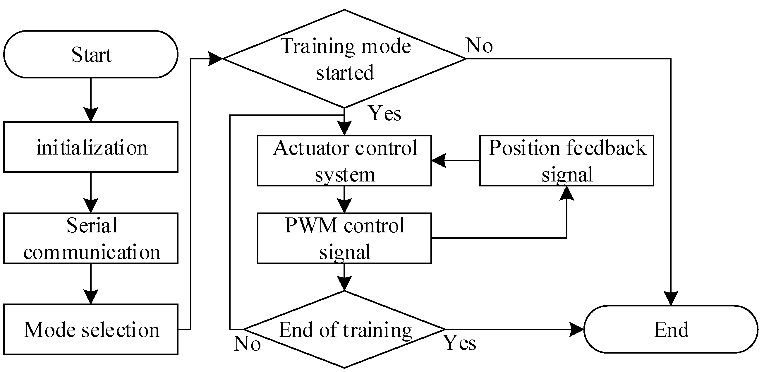
The control flow chart of the hardware system is shown in Figure 8.

2.2. Kinematics and Motion Simulation of Hand Exoskeleton Robot

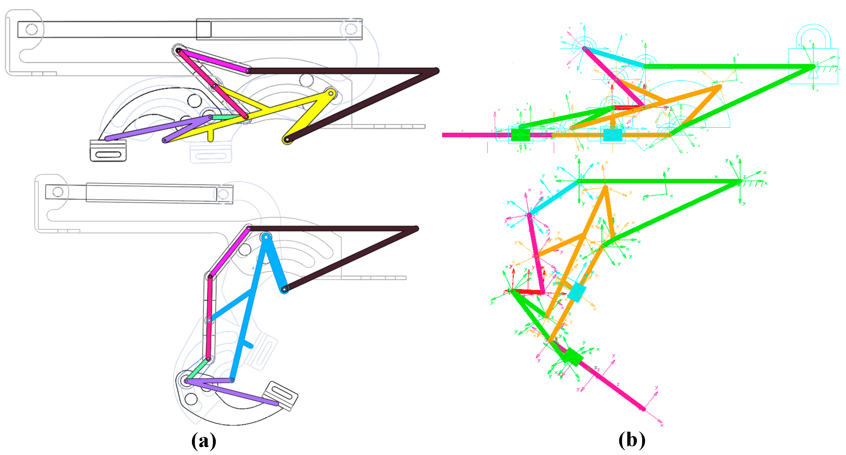
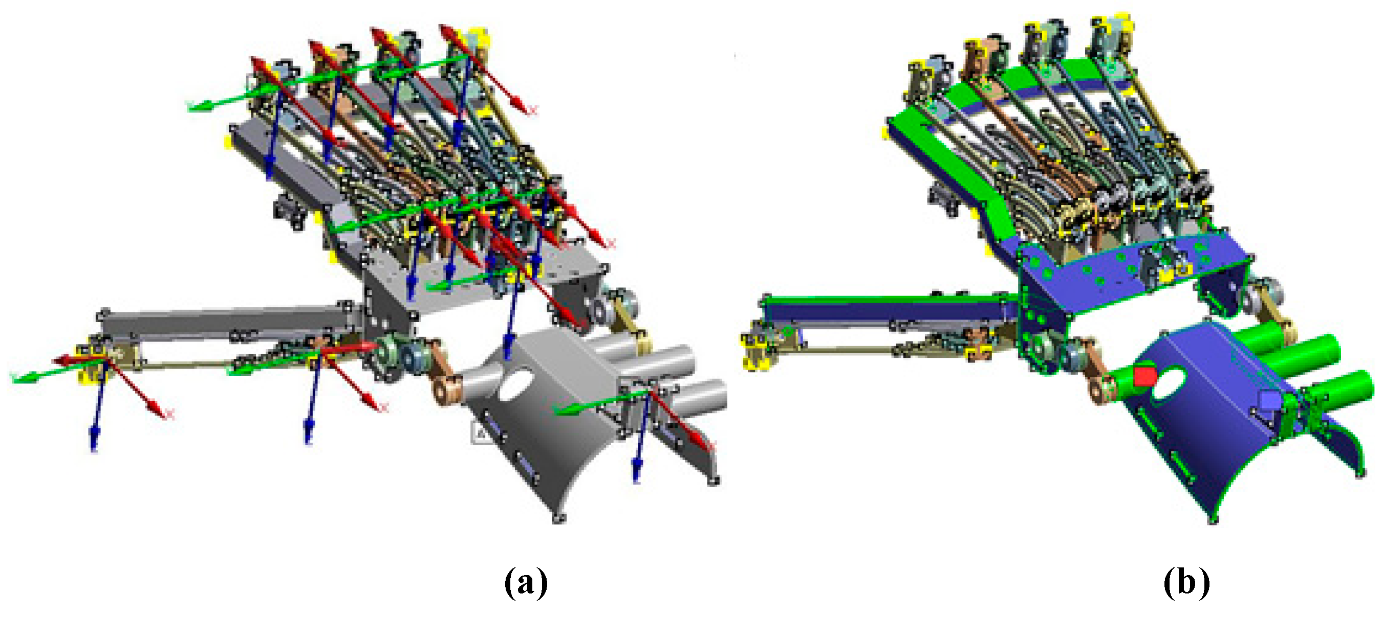
The simplified model of the hand functional rehabilitation robot designed in this paper is shown in Figure 9, in which the MCP (metacarpophalangeal) and PIP (proximal interphalangeal) joints of the fingers are combined and linked through the connecting rod structure.
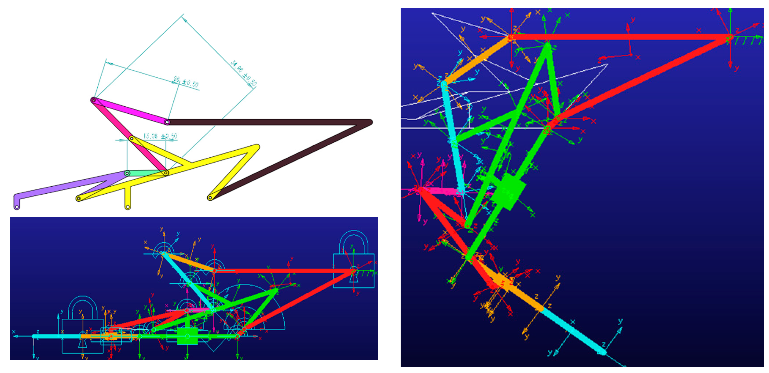
The mechanism model of finger part was simplified and the model was built in AD-AMS software, as shown in Figure 10.

2.3. Optimal Design of Exoskeleton Hand Robot Based on Topology Optimization

2.3.1. Finite Element Analysis of Hand Rehabilitation Robot

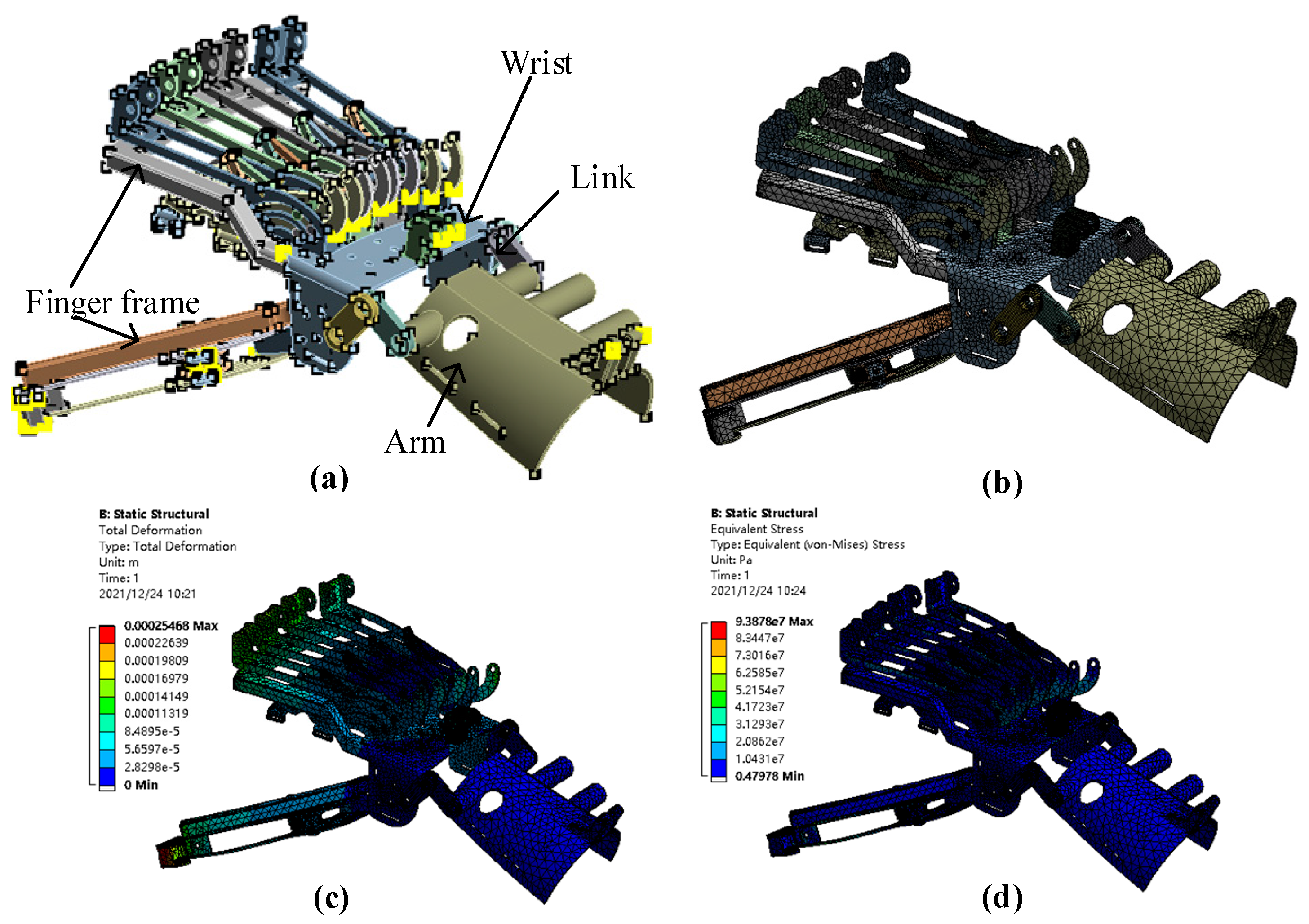
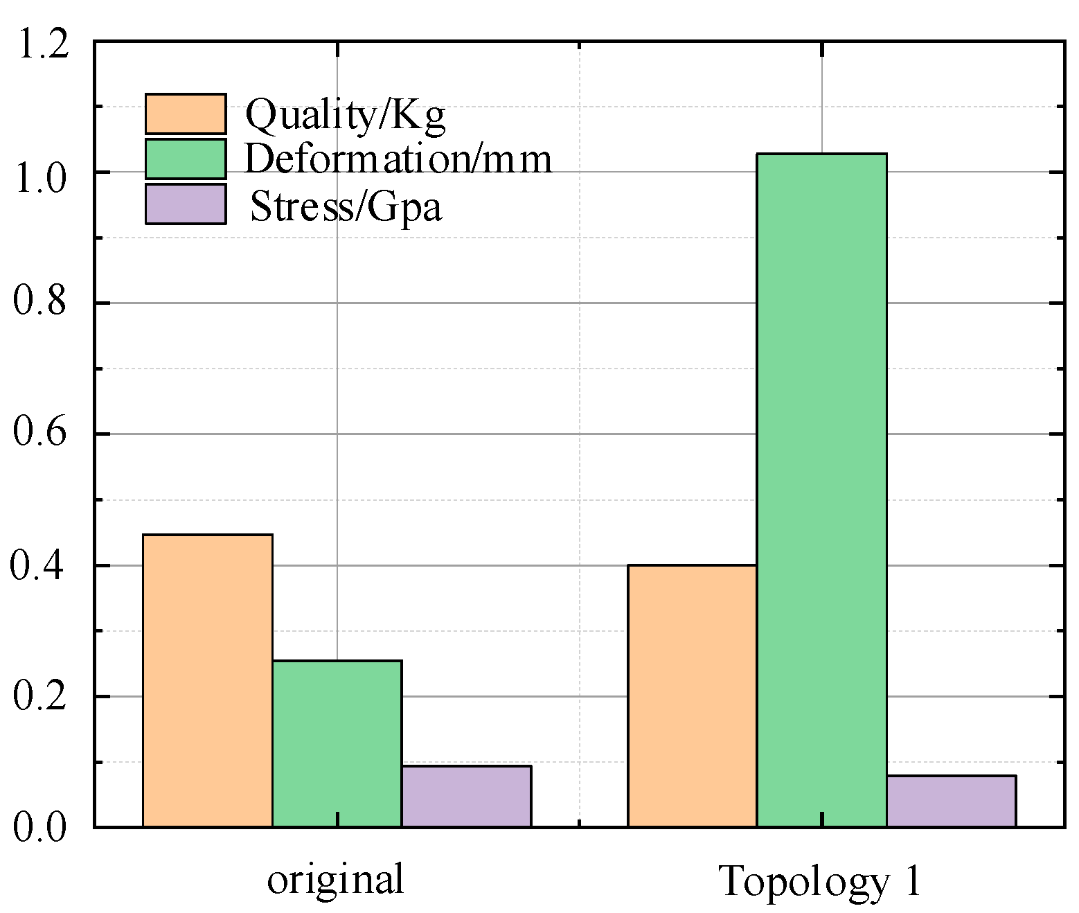
In order to reduce weight, reduce material waste and enhance durability, topology optimization is carried out for the design structure. The model is imported into ANSYS Workbench and connected to the static structural module. The material attribute is defined as aluminum alloy, and the model weight is 0.45 kg. Firstly, the mesh is divided, the constraints and loads are defined, and the maximum deformation and maximum stress values are solved, which are 0.25468 and 93.878 mpa, respectively. Then, it was connected to the topology optimization module and the optimization target under the same constraints and loads was selected.
The finite element analysis process is shown in Figure 11. Figure 11a is the schematic diagram of the structure after importing ANSYS. Figure 11b is the model after meshing, we used tetrahedron mesh to generate 113,741 nodes and 395,150 elements. Figure 11c is the stress analysis model and Figure 11d is the strain model.

2.3.2. Robot Optimization Based on Topology Method

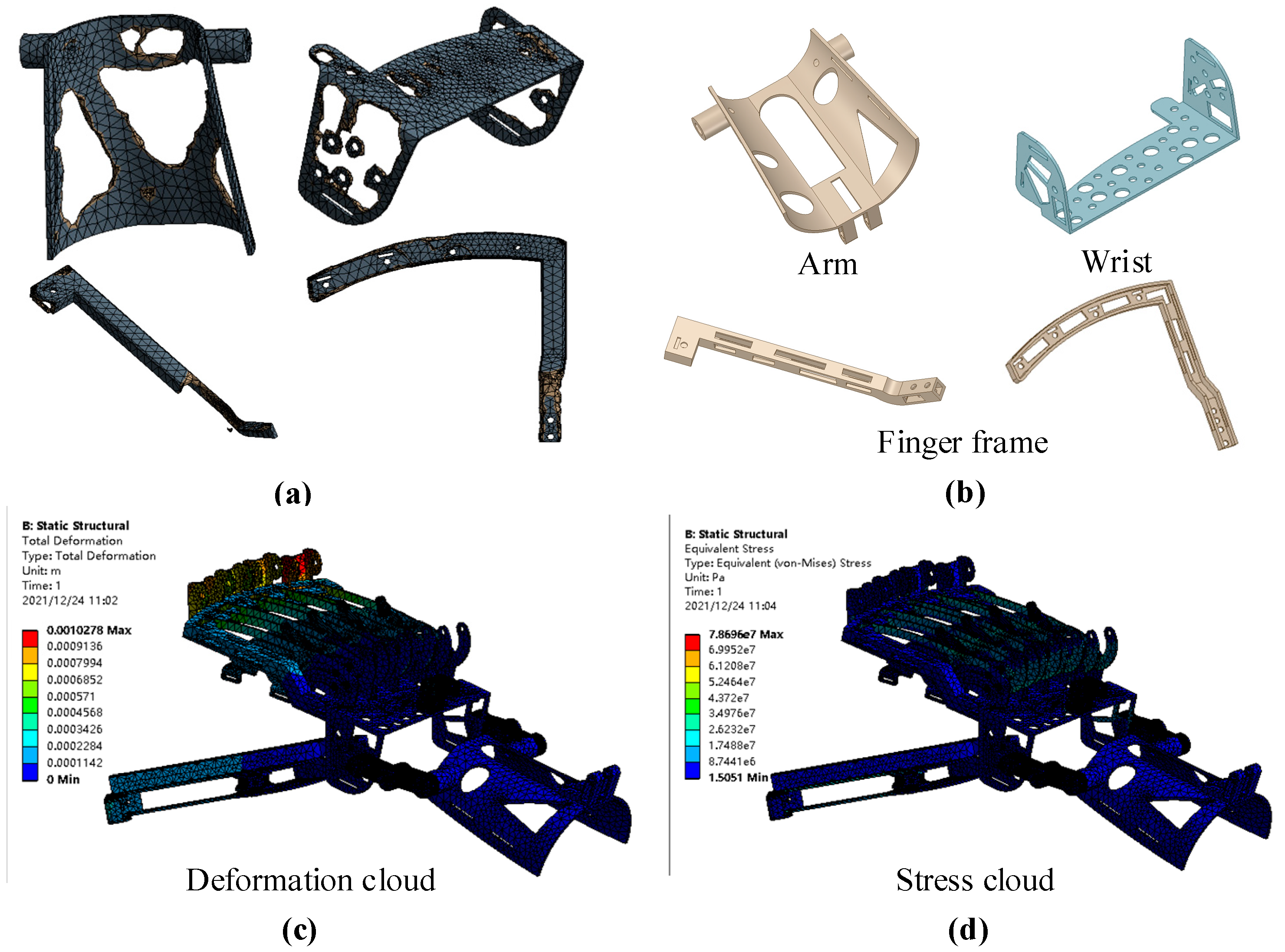
Select the arm, wrist and finger support as the optimization target, set the optimization quality as 40%, select the optimization area and start topology optimization. Output the geometry file after topology optimization, edit the file and convert it into solid geometry model, reassemble it into the assembly, and import it into static structural again. The model weight is 0.39 kg. The maximum deformation and maximum stress are 1.0278 and 78.696 mpa, respectively.
As shown in Figure 12, the topology optimization results are shown, and Figure 12a is the topology optimization generation model. Since the topology optimization-generated model is irregular, the optimized model is obtained by repairing it with 3D modeling software, as shown in Figure 12b. For the optimized structure, conduct the finite element analysis again, as shown in Figure 12c for the stress model and Figure 12d for the strain model.
The boundary conditions for the FE model in this paper is shown in Figure 13.

3. Results

3.1. Hand Function Rehabilitation Robot Prototype

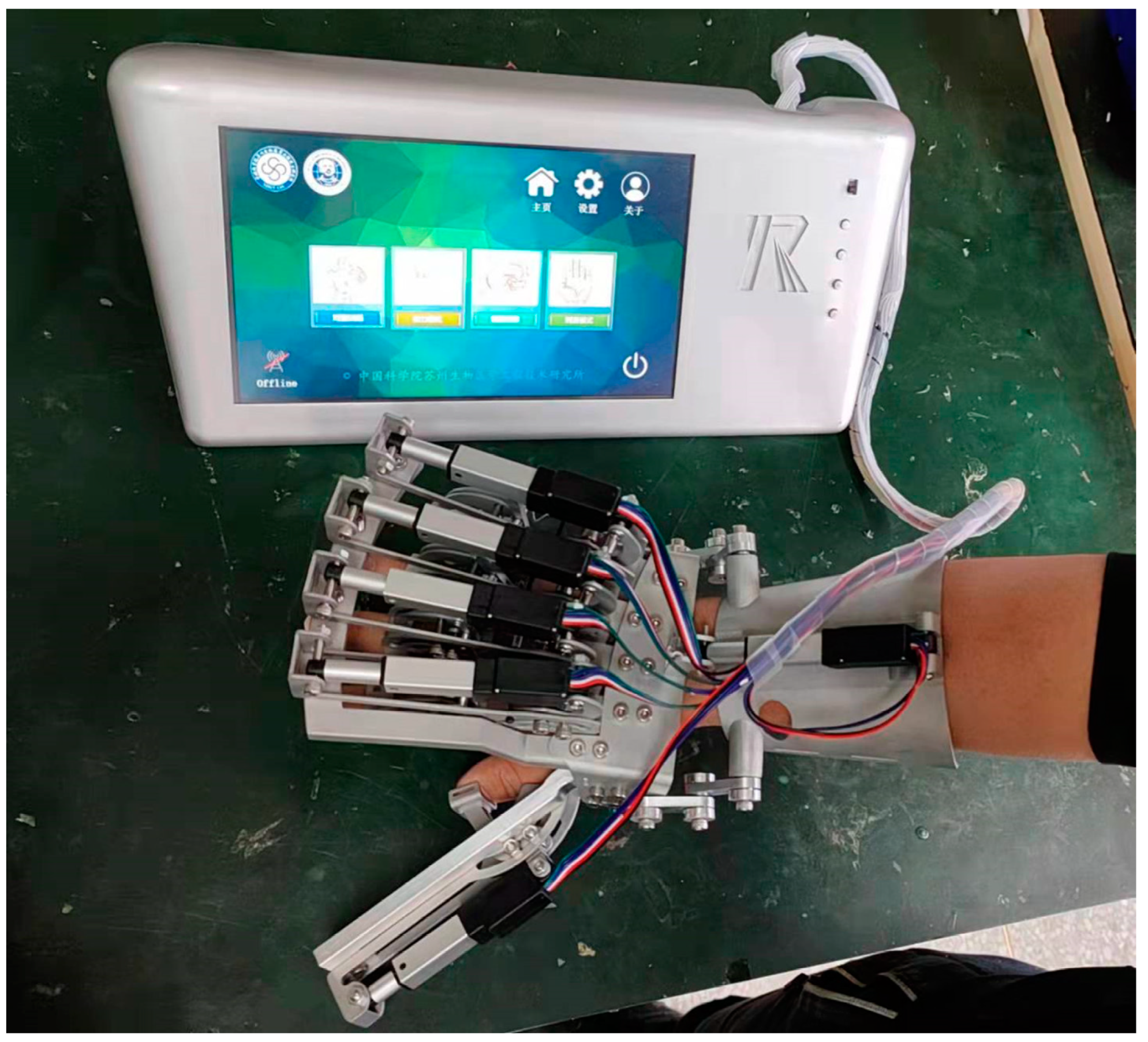
Through the structure design, hardware design and software system development described in this paper, combined with 3D printing, CNC processing, circuit processing and programming, we have completed the complete machine of the hand rehabilitation robot. The prototype of exoskeleton type hand functional rehabilitation robot is shown in Figure 14.

3.2. Hand Rehabilitation Prototype and Parameter Comparison after Topology Optimization

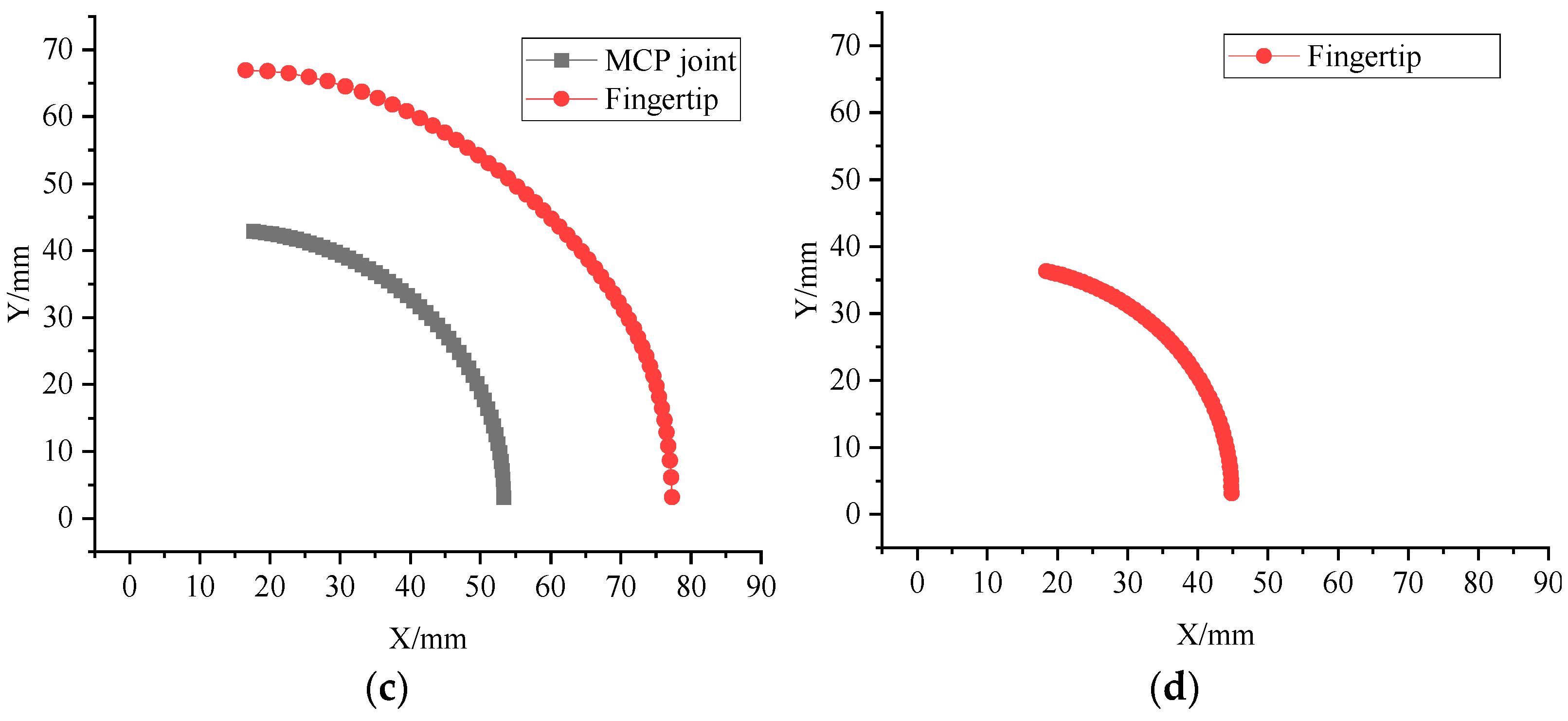
Through the mechanical model simplification and model establishment described above, the whole machine simulation model of the hand rehabilitation robot is completed. In the simulation software, the same drive as the real electric cylinder is applied to the model. Driving the finger to complete the desired motion. By collecting the motion data of fingertips and MCP joints, the motion trajectories of different fingers were drawn. The finger root was set as the motion origin, and the motion range of MCP and fingertip of different fingers are shown in Figure 15.

3.3. Hand Rehabilitation Prototype and Parameter Comparison after Topology Optimization

We consider the lightweight and weight-reduction design of the whole machine, and optimize the components through the topology optimization mentioned above. Finally, the weight-reduction version of the hand rehabilitation robot is designed and the whole machine is manufactured. The hand rehabilitation robot after topology optimization is shown in Figure 16.
Figure 17 shows the overall mass, strain information and stress information of the whole machine before and after weight reduction optimization.
It can be seen from the simulation results that the quality of the whole machine has been reduced to a certain extent under the condition of meeting the application requirements, and the feasibility of the structure has been ensured.

4. Discussion

The exoskeleton hand rehabilitation robot designed in this paper achieves good man-machine matching through kinematics design. This paper presents the design of the core driver, control system and software interface used in the design of the exoskeleton hand rehabilitation robot, and realizes the intelligent human–machine control of the exoskeleton hand rehabilitation robot. At the same time, the kinematics of the exoskeleton hand rehabilitation robot is analyzed by simulation software, and the weight reduction in the whole hand rehabilitation robot is realized by topology optimization.
The hand rehabilitation robot designed in this paper has a certain function of continuous passive rehabilitation, but the overall appearance is still too industrialized, and the appearance design lacks human elements. In the follow-up study, we plan to conduct in-depth development work for the product.
In addition to the appearance, a very important factor in the commercialization of the hand rehabilitation robot is the cost. However, the rehabilitation robot designed in this paper uses a commercial servo actuator. This basically uses half the cost of the whole hand rehabilitation robot. We are also exploring and developing alternative linear actuators. It is expected that through the development of core execution devices, the cost can be reduced, so as to make hand-held rehabilitation robot products.

5. Conclusions

In this work, we developed an exoskeleton robot for hand functional rehabilitation according to the actual needs of hand functional rehabilitation. We designed the finger parts of the exoskeleton robot through the modular design idea. The frame is used to combine the finger parts and form the overall mechanical structure of the exoskeleton hand rehabilitation robot. Subsequently, the core circuit suitable for linear servo drive is designed. At the same time, this paper develops the control algorithm and UI control interface suitable for hand function rehabilitation, thus realizing the intelligent control of hand rehabilitation robot. Considering the overall weight requirement of the exoskeleton hand rehabilitation robot, this paper uses finite element analysis and topology optimization. On the premise of ensuring the effectiveness and stability of the whole structure, the optimization and weight reduction in the whole structure are realized.
This paper shows the technologies involved in the hand rehabilitation robot we developed, including the technical details of mechanical design, hardware circuit design and program development, which provides a way of thinking for the development of subsequent rehabilitation robots. At the same time, we hope to further optimize and upgrade the developed hand rehabilitation robot in the future. It can be applied to the clinical or household use of hand function rehabilitation.

Author Contributions

Conceptualization, H.Y. and K.G.; methodology, K.G. and J.L.; software, K.G. and C.L.; validation, J.L. and C.L.; writing—original draft preparation K.G. and J.L.; writing—review and editing, K.G. and J.L.; supervision, H.Y.; project administration, K.G.; funding acquisition, H.Y. All authors have read and agreed to the published version of the manuscript.

Funding

This research was funded by the Key Research and Development Program of Jiangsu Province (Grant no. BE2021012-1). Additionally, the APC was funded by [BE2021012-1].

Institutional Review Board Statement

Not applicable.

Informed Consent Statement

Informed consent was obtained from all subjects involved in the study.

Data Availability Statement

The data presented in this study are available on request from the corresponding author.

Conflicts of Interest

The authors declare no conflict of interest.

References

  1. Long, Y.; Peng, Y. Development and Validation of a Robotic System Combining Mobile Wheelchair and Lower Extremity Exoskeleton. J. Intell. Robot. Syst. 2022, 104, 1–12. [Google Scholar] [CrossRef]
  2. Ye, W.; Li, Z.; Yang, C.; Chen, F.; Su, C.Y. Motion detection enhanced control of an upper limb exoskeleton robot for rehabilitation training. Int. J. Hum. Robot. 2017, 14, 1650031. [Google Scholar] [CrossRef] [Green Version]
  3. Shi, L.; Yu, Y.; Xiao, N.; Gan, D.; Wei, W. Biologically Inspired and Rehabilitation Robotics 2020. Appl. Bionics Biomech. 2022, 2022, 9852938. [Google Scholar] [CrossRef] [PubMed]
  4. Li, X.; Liu, J.; Li, W.; Huang, Y.; Zhan, G. Force Transmission Analysis and Optimization of Bowden Cable on Body in a Flexible Exoskeleton. Appl. Bionics Biomech. 2022, 2022, 5552166. [Google Scholar] [CrossRef] [PubMed]
  5. Gull, M.A.; Bai, S.; Bak, T. A review on design of upper limb exoskeletons. Robotics 2020, 9, 16. [Google Scholar] [CrossRef] [Green Version]
  6. Cao, D.; Wang, J.; Liu, N. Research on human sports rehabilitation design based on object-oriented technology. J. Healthc. Eng. 2021, 2021, 6626957. [Google Scholar] [CrossRef] [PubMed]
  7. Sarac, M.; Solazzi, M.; Frisoli, A. Design requirements of generic hand exoskeletons and survey of hand exoskeletons for rehabilitation, assistive, or haptic use. IEEE Trans. Haptics 2019, 12, 400–413. [Google Scholar] [CrossRef] [Green Version]
  8. Vélez-Guerrero, M.A.; Callejas-Cuervo, M.; Mazzoleni, S. Design, Development, and Testing of an Intelligent Wearable Robotic Exoskeleton Prototype for Upper Limb Rehabilitation. Sensors 2021, 21, 5411. [Google Scholar] [CrossRef]
  9. Fazli, E.; Rakhtala, S.M.; Mirrashid, N.; Karimi, H.R. Real-time implementation of a super twisting control algorithm for an upper limb wearable robot. Mechatronics 2022, 84, 102808. [Google Scholar] [CrossRef]
  10. Chen, Z.; Guo, Q.; Xiong, H.; Jiang, D.; Yan, Y. Control and Implementation of 2-DOF Lower Limb Exoskeleton Experiment Platform. Chin. J. Mech. Eng. Ji Xie Gong Cheng Xue Bao 2021, 34, 22. [Google Scholar] [CrossRef]
  11. Secciani, N.; Brogi, C.; Pagliai, M.; Buonamici, F.; Gerli, F.; Vannetti, F.; Bianchini, M.; Volpe, Y.; Ridolfi, A. Wearable Robots: An Original Mechatronic Design of a Hand Exoskeleton for Assistive and Rehabilitative Purposes. Front. Neurorobot. 2021, 15, 750385. [Google Scholar] [CrossRef] [PubMed]
  12. Moreno-SanJuan, V.; Cisnal, A.; Fraile, J.C.; Pérez-Turiel, J.; de-la-Fuente, E. Design and characterization of a lightweight underactuated RACA hand exoskeleton for neurorehabilitation. Robot. Auton. Syst. 2021, 143, 103828. [Google Scholar] [CrossRef]
  13. Sarac, M.; Solazzi, M.; Leonardis, D.; Sotgiu, E.; Bergamasco, M.; Frisoli, A. Design of an Underactuated Hand Exoskeleton with Joint Estimation. In Advances in Italian Mechanism Science; Springer: Cham, Switzerland, 2017; pp. 97–105. [Google Scholar]
  14. Aragón-Martínez, A.; Arias-Montiel, M.; Lugo-González, E.; Tapia-Herrera, R. Two-finger exoskeleton with force feedback for a mobile robot teleoperation. Int. J. Adv. Robot. Syst. 2020, 17, 1729881419895648. [Google Scholar] [CrossRef]
  15. Refour, E.M.; Sebastian, B.; Chauhan, R.J.; Ben-Tzvi, P. A General Purpose Robotic Hand Exoskeleton with Series Elastic Actuation. J. Mech. Robot. 2019, 11, 060902. [Google Scholar] [CrossRef] [PubMed]
  16. Carbone, G.; Gerding, E.C.; Corves, B.; Cafolla, D.; Russo, M.; Ceccarelli, M. Design of a Two-DOFs Driving Mechanism for a Motion-Assisted Finger Exoskeleton. Appl. Sci. 2020, 10, 2619. [Google Scholar] [CrossRef] [Green Version]
  17. Ceccarelli, M.; Morales-Cruz, C. A prototype characterization of ExoFinger, a finger exoskeleton. Int. J. Adv. Robot. Syst. 2021, 18, 17298814211024880. [Google Scholar] [CrossRef]
  18. Hernández-Santos, C.; Davizón, Y.A.; Said, A.R.; Soto, R.; Felix-Herrán, L.C.; Vargas-Martínez, A. Development of a Wearable Finger Exoskeleton for Rehabilitation. Appl. Sci. 2021, 11, 4145. [Google Scholar] [CrossRef]
  19. Almusawi, H.; Husi, G. Design and Development of Continuous Passive Motion (CPM) for Fingers and Wrist Grounded-Exoskeleton Rehabilitation System. Appl. Sci. 2021, 11, 815. [Google Scholar] [CrossRef]
  20. Chowdhury, A.; Nishad, S.S.; Meena, Y.K.; Dutta, A.; Prasad, G. Hand-Exoskeleton Assisted Progressive Neurorehabilitation using Impedance Adaptation based Challenge Level Adjustment Method. IEEE Trans. Haptics 2018, 12, 128–140. [Google Scholar] [CrossRef] [Green Version]
  21. Kim, U.; Jung, D.; Jeong, H.; Park, J.; Jung, H.M.; Cheong, J.; Choi, H.R.; Do, H.; Park, C. Integrated linkage-driven dexterous anthropomorphic robotic hand. Nat. Commun. 2021, 12, 7177. [Google Scholar] [CrossRef]
  22. Vanteddu, T.; Ben-Tzvi, P. Stable Grasp Control with a Robotic Exoskeleton Glove. J. Mech. Robot. 2020, 12, 061015. [Google Scholar] [CrossRef] [PubMed]
  23. Castiblanco, J.C.; Mondragon, I.F.; Alvarado-Rojas, C.; Colorado, J.D. Assist-As-Needed Exoskeleton for Hand Joint Rehabilitation Based on Muscle Effort Detection. Sensors 2021, 21, 4372. [Google Scholar] [CrossRef] [PubMed]
  24. Ou, Y.K.; Wang, Y.L.; Chang, H.C.; Chen, C.C. Design and Development of a Wearable Exoskeleton System for Stroke Rehabilitation. Healthcare 2020, 8, 18. [Google Scholar] [CrossRef] [PubMed] [Green Version]
  25. Jo, I.; Park, Y.; Lee, J.; Bae, J. A portable and spring-guided hand exoskeleton for exercising flexion/extension of the fingers. Mech. Mach. Theory 2019, 135, 176–191. [Google Scholar] [CrossRef]
  26. Zhang, F.; Lin, L.; Yang, L.; Fu, Y. Design of an Active and Passive Control System of Hand Exoskeleton for Rehabilitation. Appl. Sci. 2019, 9, 2291. [Google Scholar] [CrossRef] [Green Version]
  27. Li, M.; He, B.; Liang, Z.; Zhao, C.G.; Chen, J.; Zhuo, Y.; Xu, G.; Xie, J.; Althoefer, K. An Attention-Controlled Hand Exoskeleton for the Rehabilitation of Finger Extension and Flexion Using a Rigid-Soft Combined Mechanism. Front. Neurorobot. 2019, 13, 34. [Google Scholar] [CrossRef] [Green Version]
  28. Cheng, L.; Chen, M.; Li, Z. Design and Control of a Wearable Hand Rehabilitation Robot. IEEE Access 2018, 6, 74039–74050. [Google Scholar] [CrossRef]
  29. Li, K.; Li, Z.; Zeng, H.; Wei, N. Control of Newly-Designed Wearable Robotic Hand Exoskeleton Based on Surface Electromyographic Signals. Front. Neurorobot. 2021, 15, 711047. [Google Scholar] [CrossRef]
  30. Lu, Z.; Tong, K.Y.; Shin, H.; Li, S.; Zhou, P. Advanced Myoelectric Control for Robotic Hand-Assisted Training: Outcome from a Stroke Patient. Front. Neurol. 2017, 8, 107. [Google Scholar] [CrossRef] [Green Version]
  31. Xu, P.; Xia, D.; Li, J.; Zhou, J.; Xie, L. Execution and perception of upper limb exoskeleton for stroke patients: A systematic review. Intell. Serv. Robot. 2022, 15, 557–578. [Google Scholar] [CrossRef]
  32. Souhail, A.; Vessakosol, P. Low cost soft robotic gloves for at-home rehabilitation and daily living activities. J. Autom. Mob. Robot. Intell. Syst. 2019, 13, 14–26. [Google Scholar]
  33. Ahmed, T.; Assad-Uz-Zaman, M.; Islam, M.R.; Gottheardt, D.; McGonigle, E.; Brahmi, B.; Rahman, M.H. Flexohand: A Hybrid Exoskeleton-Based Novel Hand Rehabilitation Device. Micromachines 2021, 12, 1274. [Google Scholar] [CrossRef] [PubMed]
  34. Birouaș, F.I.; Țarcă, R.C.; Dzitac, S.; Dzitac, I. Preliminary Results in Testing of a Novel Asymmetric Underactuated Robotic Hand Exoskeleton for Motor Impairment Rehabilitation. Symmetry 2020, 12, 1470. [Google Scholar] [CrossRef]
  35. Kabir, R.; Sunny, M.S.; Ahmed, H.U.; Rahman, M.H. Hand Rehabilitation Devices: A Comprehensive Systematic Review. Micromachines 2022, 13, 1033. [Google Scholar] [CrossRef] [PubMed]
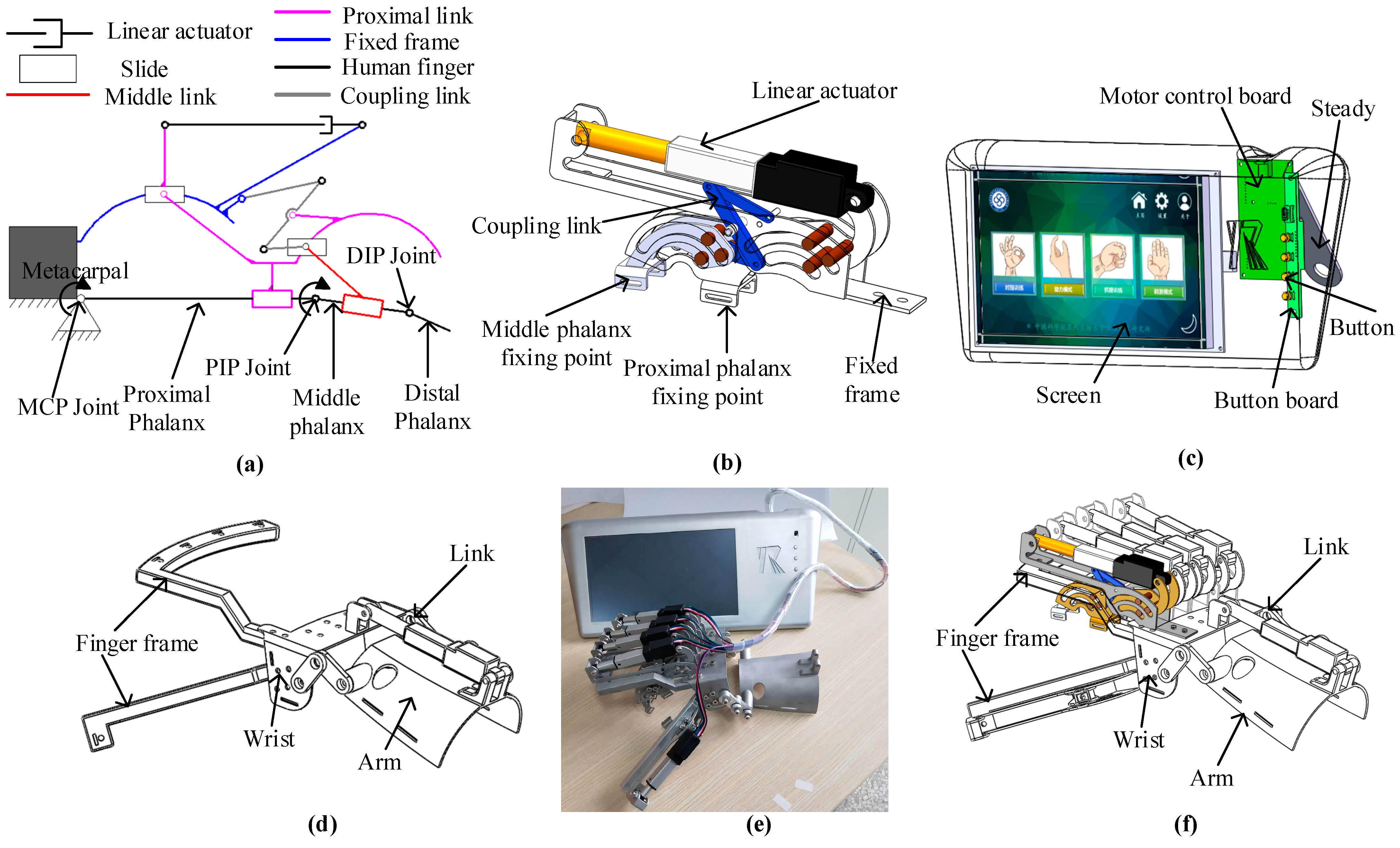
Figure 1. Overall design of exoskeleton hand rehabilitation robot. (a) A simplified model of single finger structure with joint linkage; (b) structure design of rehabilitation training for single finger; (c) composition of control host, interactive interface and control hardware; (d) frame design for finger mounting; (e) assembled whole robot; (f) the whole structure of hand rehabilitation robot.
Applsci 12 10580 g001
Figure 2. Control frame diagram of hand rehabilitation robot.
Applsci 12 10580 g002
Figure 3. Core linear actuator of hand rehabilitation robot.
Applsci 12 10580 g003
Figure 4. Schematic diagram of step-down circuit and level conversion.
Applsci 12 10580 g004
Figure 5. Schematic diagram of the circuit of the rehabilitation robot.
Applsci 12 10580 g005
Figure 6. The main control circuit diagram of the rehabilitation robot.
Applsci 12 10580 g006
Figure 7. The control software interface of the rehabilitation robot.
Applsci 12 10580 g007
Figure 8. Flow chart of control system.
Applsci 12 10580 g008
Figure 9. Simplified structure of finger part of hand rehabilitation robot. (a) The process of simplifying the model into connecting rod; (b) Establishment of simulation model of connecting rod.
Applsci 12 10580 g009
Figure 10. The mechanism model of single finger part.
Applsci 12 10580 g010
Figure 11. (a) Simplified model; (b) finite element model; (c) deformation cloud; (d) stress cloud.
Applsci 12 10580 g011
Figure 12. (a) Topology optimization output results; (b) edit the output model and convert it into a solid model; (c) deformation cloud after topology optimization; (d) stress cloud after topology optimization.
Applsci 12 10580 g012
Figure 13. The boundary conditions (a) static analysis; (b) the optimized boundary conditions of topology.
Applsci 12 10580 g013
Figure 14. Prototype of hand rehabilitation robot before topology optimization.
Applsci 12 10580 g014
Figure 15. Motion trajectory of different finger simulations. (a) Index finger (same size as ring finger); (b) middle finger; (c) little thumb; (d) thumb.
Applsci 12 10580 g015aApplsci 12 10580 g015b
Figure 16. The model and prototype of hand robot after topology optimized.
Applsci 12 10580 g016
Figure 17. The effect of topology optimization.
Applsci 12 10580 g017
Publisher’s Note: MDPI stays neutral with regard to jurisdictional claims in published maps and institutional affiliations.