Article

Dielectric Slabs-Based Lens for Millimeter-Wave Beamforming

by
Ali H. Alqahtani
1,*,
Yosef T. Aladadi
2 and
Mohammed T. Alresheedi
2
1
Department of Applied Electrical Engineering, Al-Muzahimya Campus, College of Applied Engineering, King Saud University, Riyadh 11421, Saudi Arabia
2
Department of Electrical Engineering, King Saud University, Riyadh 11421, Saudi Arabia
*
Author to whom correspondence should be addressed.
Appl. Sci. 2022, 12(2), 638; https://doi.org/10.3390/app12020638
Submission received: 23 November 2021 / Revised: 29 December 2021 / Accepted: 5 January 2022 / Published: 10 January 2022
(This article belongs to the Special Issue Development of UWB Antennas and Microwave Components)

Abstract

:
This paper proposes a dielectric slabs-based lens for millimeter-wave beamforming systems. The proposed lens is based on the graded steps of the effective refractive index of the semi-spherical lens. It consists of multiple dielectric slabs that match the selected gradient effective refractive index. These slabs have the same thicknesses and different radii. The slab thickness in this lens should not exceed a quarter of the operating wavelength to keep on a similar effective refractive index of the original semi-spherical lens. A horn antenna is used to examine the performance of the designed lens at 28 GHz frequency in terms of the maximum gain, sidelobe level, and 3 dB beamwidth. Sixteen switchable horn antennas are used to demonstrate lens capability for millimeter-wave beamforming. Every single antenna element is selected individually, thus the dielectric lens steers and enhances the corresponding radiation of the selected element in the desired direction.

1. Introduction

The use of millimeter-wave bands for next-generation wireless communication networks, such as fifth-generation (5G) mobile systems, has piqued the interest of researchers as the demand for high data rates grows. [1]. However, millimeter-wave communications pose many diverse challenges due to the large channel bandwidth, unique channel characteristics, hardware constraints, the concrete path, and penetration losses at millimeter wavelengths [2,3]. As a result, antenna beamforming is proposed for establishing and maintaining a reliable millimeter-wave communication link. Beamforming in 5G is the modern, powerful technique for the intended user/direction coverage using the narrow beamwidth radiation patterns [3]. Beamforming techniques are based on steering the direction of the main lobe of the radiation by switching the elements of an antenna array or by changing the relative phases of radio frequency (RF) signals driving the array elements. The beamforming antenna array technologies are combined with massive multiple-input multiple-output (MIMO) systems and multi-beam antenna array systems to play a crucial role in 5G wireless communication systems [4,5].
However, despite high directivity and beam scanning of antenna array beamformers, their practical implementation at millimeter-wave frequencies is complex and expensive [6]. So, researchers focus on innovative lenses to be used in beamforming systems of 5G millimeter-wave to reduce the cost and the complexity [7]. The passive phase shifter lens enables beamforming without a heavy network of phase shifters of antenna array beamformers, while the energy-focusing property of the lens achieves gain and directivity. In spherical or semi-spherical lenses, the beam traveling along the principal axis of the lens is focused on a spot, known as the focal point. Conversely, an EM radiation source placed at the focal point can be converted into a directional beam by the lens, so an object with an image at infinity and vice versa. Besides using these lenses as passive phase shifters, they are used for beam collimation and deflection in the microwave range [8] and cloaks in the optical range [9]. The most common lenses used at the millimeter-wave frequencies are the Luneburg and Maxwell fisheye lenses [10]. The effective refractive index varies in the range 1– 2 for classical Luneburg lenses and in 1–2 for Maxwell fisheye lenses [10]. Variation of similar lens types is generally designed based on the transformation optics theory. The Graded refractive index of the material lens can achieve different focusing properties. The diameter of the spherical lens is inversely proportional to the achievable half-power beam width (HPBW). Theoretical conversion of 3D lens action on the 2D surface was demonstrated via focusing beam in a limited azimuthal or elevation plane [11]. Metallic parallel-plate waveguide (PPWG) structures represent the simplest periodic artificial sub-wavelength structures of graded refractive index (GRIN) metamaterials implemented for designing lenses in both microwave and sub-terahertz ranges [12,13]. The gradient refractive index of the PPWG cells can be attained by gradually modifying their geometrical parameters. A metasurfaces-based lens with field control capabilities to achieve a similar graded-index principle is presented in [14]. A broadband low-loss lens was designed based on metamaterials [15]. Another metamaterial-based thin planar lens is presented in [16] to be used with linear substrate integrated waveguide antenna array for spatial beamforming. A 3D metasurfaces-based lens is realized in [17] machined by drilling inhomogeneous holes in multilayered dielectric plates.
Although, spherical or semi-spherical dielectric lenses are isotropic and focus the radiation in both azimuthal and elevation planes. However, these lenses are challenging to be fabricated and need specific mechanical or printing devices. The metallic lens also behaves as anisotropic and cannot be manufactured for elevation and azimuthal planes in the same design. In addition, they are expensive and complex. Therefore, there is a crucial need for designing a dielectric-based lens, which is simple in manufacturing and can be modified easily. GRIN lens using 3D printing technology were presented in [18,19,20]. A-holes/voids in the lens design were included to lower the limit on the available refractive index range. These lenses were a good approximation to semi-spherical lenses for the lower frequencies where the cell size is enough to make a hole in. Therefore this approximation will not be valid for the extreme case of a solid dielectric block and dielectric blocks with very small holes, especially for high frequencies. A GRIN-like dielectric slab lens was also studied in [21]. The researchers used dielectric slabs with different widths and equal thicknesses, separated by equal air gabs. The concentration of the number of gaps varies radially and makes the dielectric slab a smoothly graded-index media, which gives it focusing or diverging properties. This lens is more efficient for the higher frequencies, but it is still needed to connect these slabs together as a whole lens. In addition, the air gap size can have a significant effect on the performance of the lens, especially on the focal distance. The limitation related to the air-gabs was solved in [22]. Researchers in this recently published paper utilized dielectric slabs that have the same widths, different thicknesses, and different lengths.
In this paper, a dielectric slabs-based lens is designed for millimeter-wave beamforming in both azimuth and elevation planes. This lens is created by discretizing the semi-spherical lens to several slabs based on the effective medium theory concept. These slabs can be fabricated with a circular shape with different radii and the same thickness not exceeding a quarter of the operating wavelength to keep on the similar effective refractive index of the original semi-spherical lens. The effect of air/epoxy materials within the dielectric slabs, maximum gain, sidelobe levels, and HPBW are investigated to test the performance of the designed lens. The millimeter-wave beamforming capabilities based on the proposed lens are also demonstrated by using 16 switchable horn antennas.

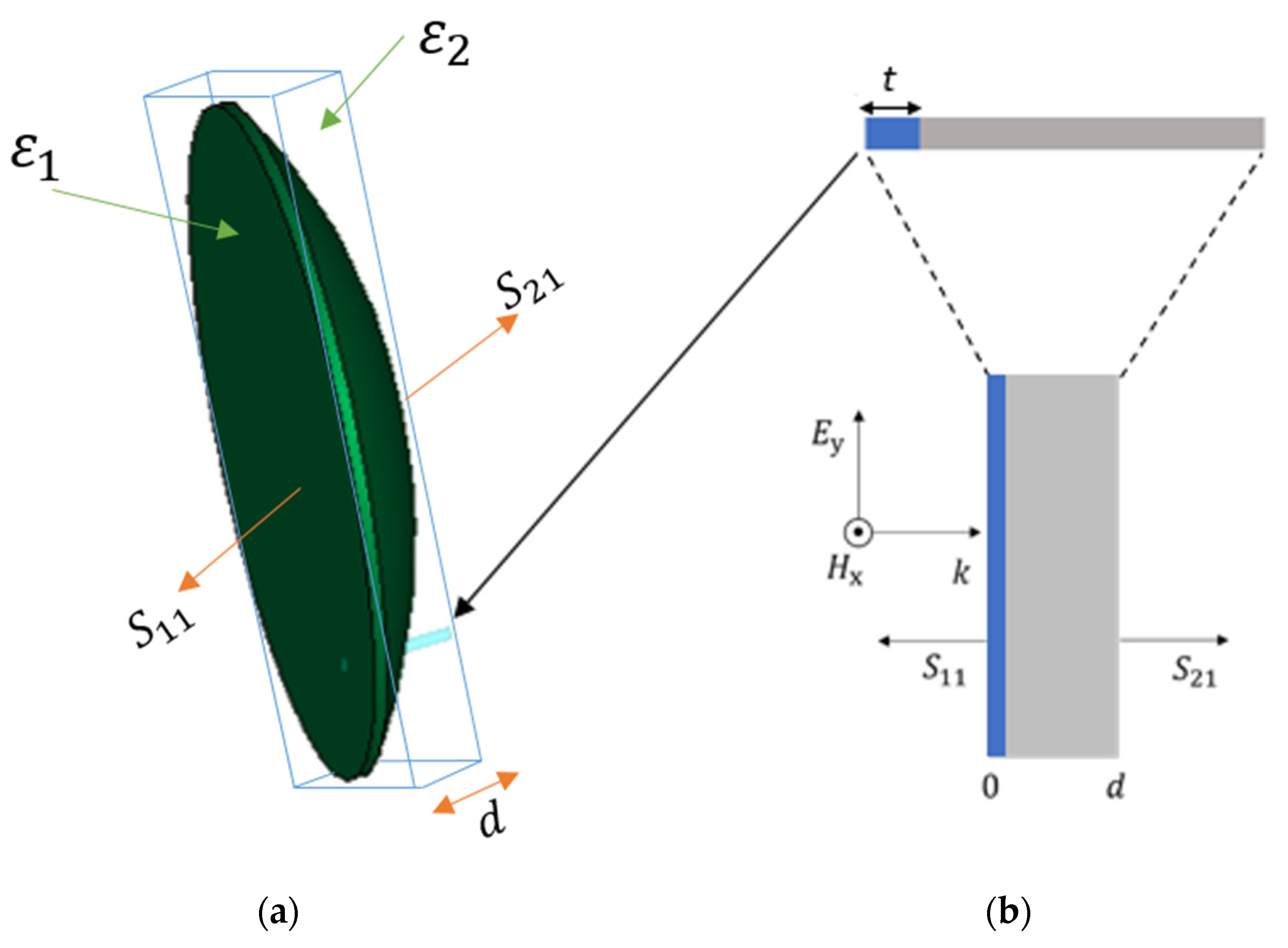
2. Dielectric Slabs-Based Lens Design

The semi-spherical lens (see Figure 1a) is assumed as a slab with thickness d to investigate if it is an effective refractive index at each position on the lens. The lens slab consists of two materials, regardless the other material is air or not. Calculating the scattering parameters of the whole lens slab (Figure 1a) cannot give the required information about the effective refractive index at each position. Therefore, to investigate the value of the effective refractive index at any position on the slab lens, a small square point in the lens is taken and expanded to take slab shape (as shown in Figure 1b). For normal incident plane waves on the slab, the relationships between the complex refractive index ( n e f f ) with the S-parameters [23,24] are given by:
n e f f = i κ d   l n ( S 11 1 S 21 ( z e f f 1 z e f f + 1 ) ) .
where d is the slab thickness, κ is the free-space wavenumber, S 11 is the reflected scattering parameter, S 21 is the transmitted scattering parameter and z e f f is the complex effective wave impedance, which is given as:
z e f f = ± ( 1 + S 11 ) 2 S 21 2 ( 1 S 11 ) 2 S 21 2
For passive materials, the real value of the imaginary value of the complex refractive index and the complex wave impedance must be greater or equal to zero. Therefore, the sign of z e f f must be determined according to those conditions. The investigated slabs consist of homogeneous polyetherimide (PEI) plastic material ( ε = 3) of thickness,   t , and air of thickness, d t .
The scattering parameters ( S 11 and S 21 ) are determined numerically using a full-wave simulator for a vertically polarized plane wave normally incident on the investigated slabs with different t / d ratios (0, 0.2, 0.4, 0.6, 0.8, 1). A finite element method (FEM) solver in CST is used to obtain the approximate solution of the electromagnetic boundary problem. Floquet’s ports are assigned using the unit cell boundaries with normal incidence. The corresponding effective refractive index is computed from the numerical scattering parameters data (see Equation (1)) and presented in Figure 2.
An analytical formula can be derived to describe the approximate effective refractive index ( n e f f ) of a slab consisting of two dielectric materials with permittivities ε 1 , and ε 2 and thickness t , and ( d t ) , respectively, as given by:
n e f f ( ε 1 t + ε 2 ( d t ) ) / d
Equation (3) represents approximated formula to do an initial calculation of the target effective refractive index with different slab thicknesses. The numerical values of the effective refractive index of the investigated slab are similar to the analytical values computed from Equation (3), as shown in Figure 2.
The effective refractive index behaves as a continuous refractive index of the semi-spherical lens when the change in the dielectric thickness, t Δ is fixed and very small. However, the behavior of the effective refractive index is stepped if the t Δ is considerable compared to the operating wavelength. Therefore, the dielectric slabs-based lens is designed by discretizing the semi-spherical dielectric lens to several slabs corresponding to the selected effective refractive index, as shown in Figure 3.
The slab thickness is constant, whereas the radius of each slab is variable and depends on the total radius of the semi-spherical lens.

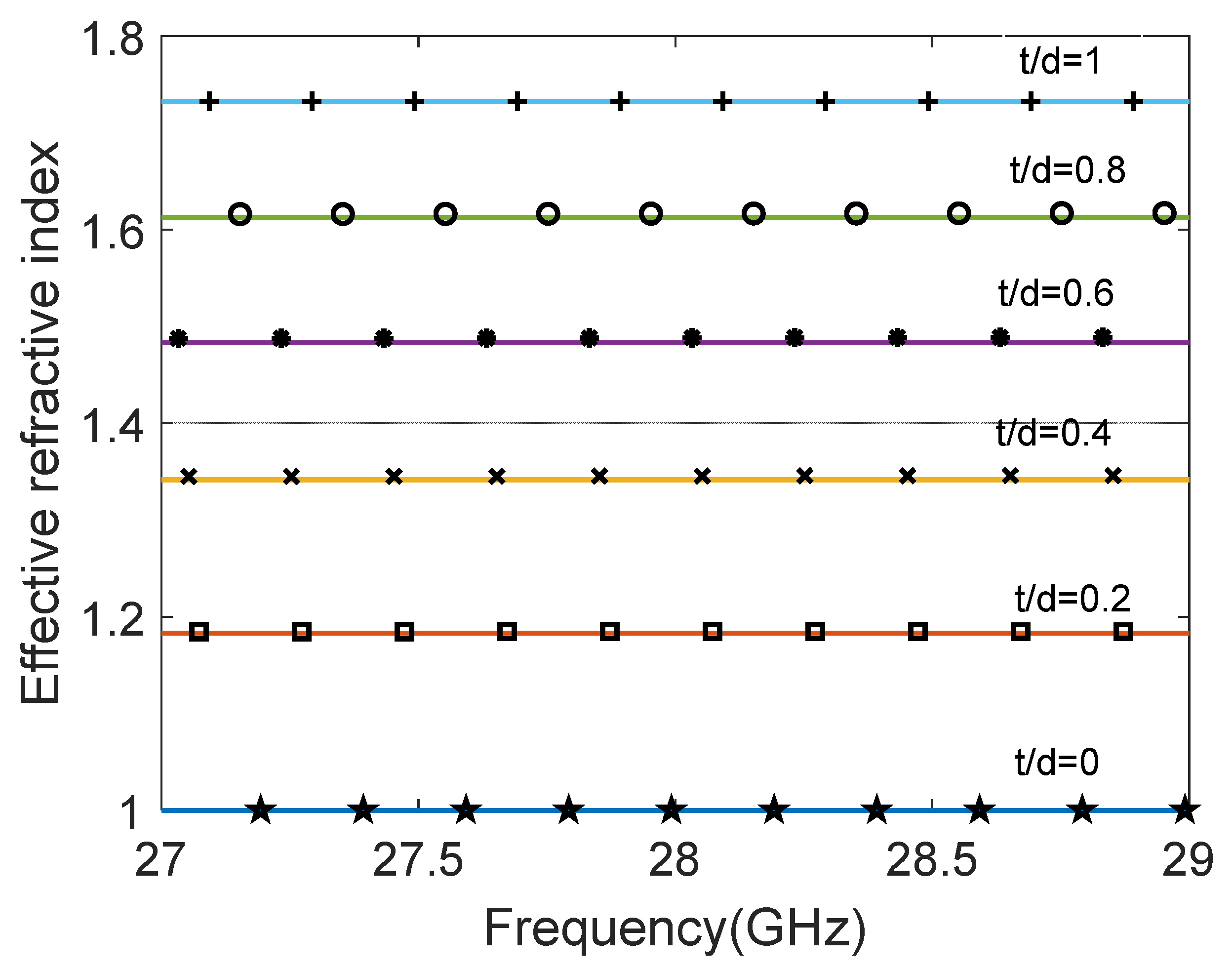
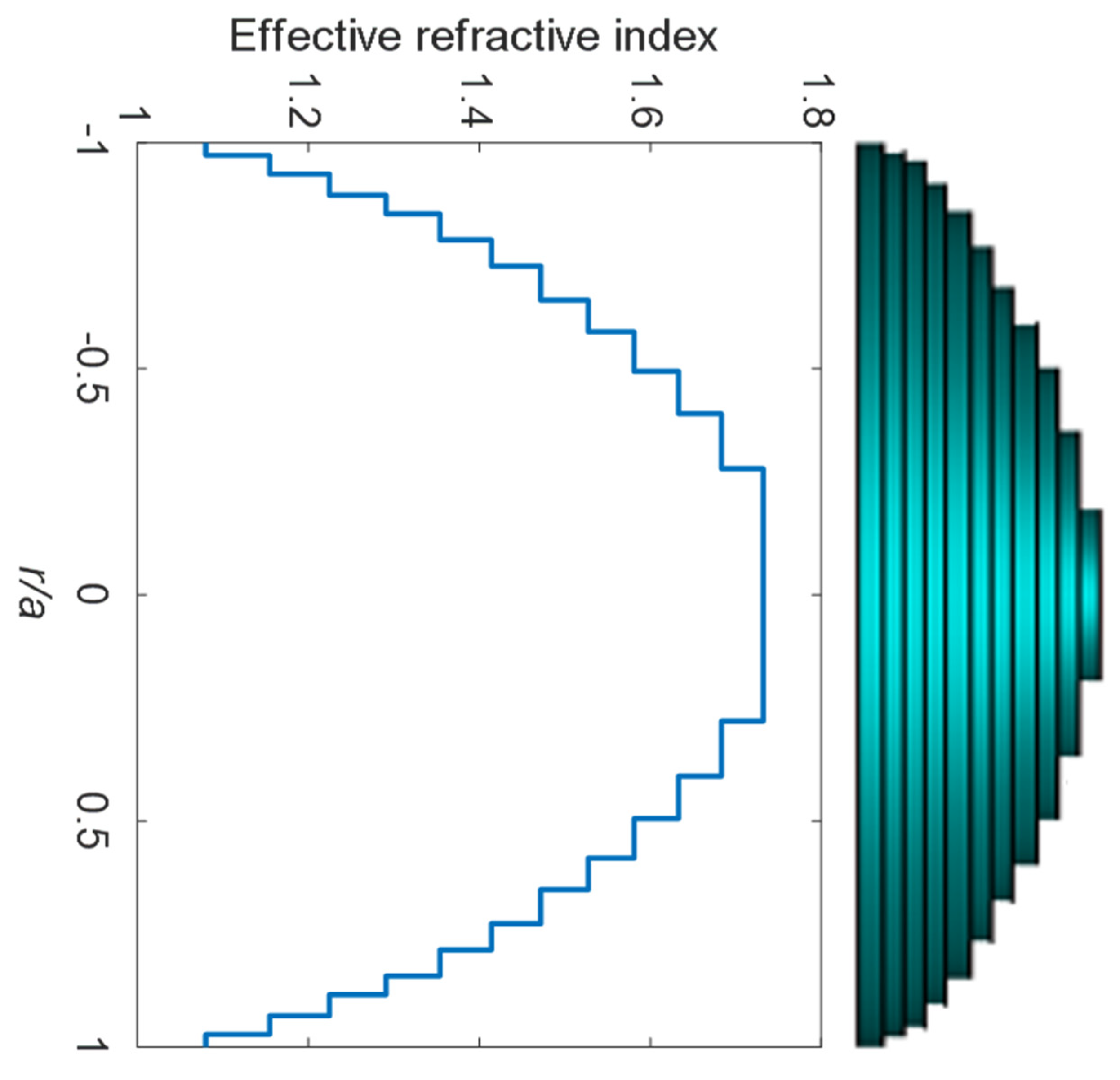
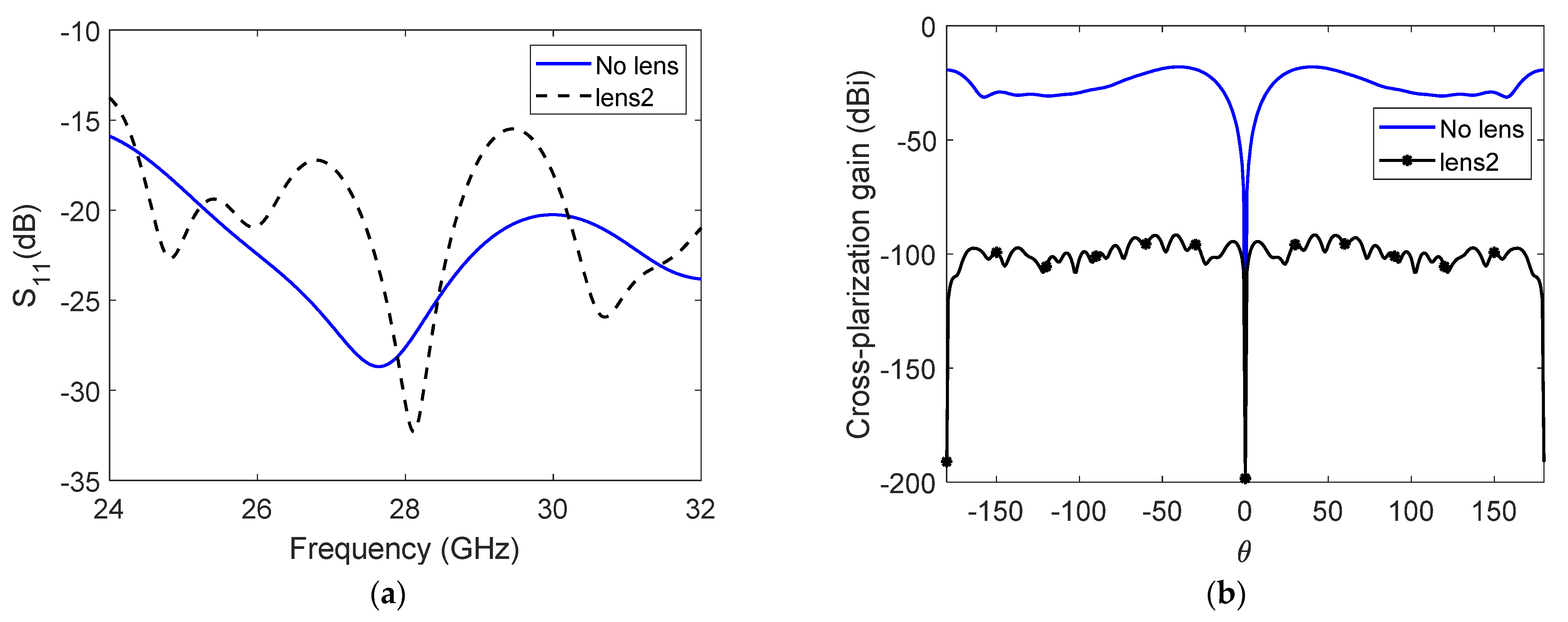
3. Discussion and Simulation Results

Figure 1a shows the horn antenna with the designed lens. The antenna port is excited by a Gaussian pulse, polarized along the y-axis and propagating along the +z-axis. The numerical solution is performed for open boundaries of the electromagnetic problem (far-field problem) using the finite integration technique (FIT) solver in CST. The performance of the proposed lens is examined in four different design cases. Lenses 1 and 2 represent the proposed dielectric slabs-based lenses with different slab thicknesses. The effect of the air gaps or epoxy materials between the slabs is also investigated in lenses 3 and 4, respectively. Figure 4 shows the horn antennas’ radiation pattern without and with the designed lens in Figure 3. The first curve represents the radiation pattern of a horn antenna without any lens. The second one (lens 1) is the radiation pattern of the reconfigurable lens with t Δ = 0.2 mm, and 55 slabs. The third one represents the radiation pattern of the reconfigurable lens (lens 2) with t Δ = 1 mm, and 11 slabs. The air gaps are investigated in lens 3, in which the slab thickness is 0.9 mm, air gap thickness is 0.1 mm, and 11 slabs. Lens 4 is similar to lens 3 except replacing air gaps with epoxy materials ( ε   = 4, σ = 0.2   S / m ). Figure 4 shows that the co-polarized radiation patterns of all designed lenses are identical. The gain for each one is around 30 dBi at 28 GHz, and 10° HPBW. Air gab’s effect is minimal and can be neglected, as shown in the dotted blue line. The effect of the epoxy materials appears only in increasing the side lobes; however, this effect is still small. The results prove that the small gap of air or epoxy does not degrade the performance of the designed lens. Increasing the number of slabs from 11 slabs with t Δ = 1 mm = λ / 10 to 55 slabs with t Δ = 0.2 mm = λ / 100 do not give any extra enhancements. Therefore, the recommended slab thickness is λ / 10 < t Δ < λ / 4 according to the available commercial dielectric thickness and the effective medium theory. In addition, the gain, HPBW, and sidelobe level can also contribute to the selection of the number of the used slabs.
The reflection coefficient of the antenna port with and without the designed lens 2 is shown in Figure 5a. For both results, the S 11 is below −10 dB over all the investigated bands. Figure 5b shows the cross-polarization gain with and without the designed lens 2. There is evidence of enhancement in the cross-polarization level when lens 2 is used.
Figure 6 shows the co-polarized radiation pattern of the horn antenna with the designed lens (lens 2), validated using two different full-wave solvers, which are the finite element method (FEM) and the finite integration technique (FIT) solvers in CST. The finite element method (FEM) uses swiping frequency excitation waves with a tetrahedral mesh of 234,024 cells. The FIT solver uses the gaussian excitation pulse with a hexahedral mesh of 851,250 cells.
Until now, we have only tested the radiation pattern parameters for one horn antenna. Therefore, 16 switchable rectangular horn antennas are introduced to examine the proposed lens for millimeter-wave beamforming for different positions of a single excited antenna. In each time, only one antenna element is on, and the other elements are off. These antennas are arranged in xy plane to be symmetric with the lens center, as shown in Figure 7. The diameter of the aperture area of the designed lens is a = 173 mm, the optimized focal point is f = 65.62 mm, and the number of slabs is 13 with a thickness t Δ = 2.67 mm = λ / 4 . Horn antennas are designed to work at 28 GHz and arranged to cover a circular area of a diameter of 150.7 mm.
Figure 8 shows the co-polarized radiation patterns of 16 switchable horn antennas with the designed reconfigurable lens. The radiation direction is in both elevation and azimuth plane, which is missed in the metamaterials-based lens. The scanning θ angle range cover from around θ = 30 ° to θ = 30 ° , and 5.9 ° 7.8 ° HPBW. The ϕ angle cover from − 70 ° to 70 ° . The maximum gain range is between 26.6 and 27.9 dBi.
The reflection coefficients of four selected antennas with the designed lens are shown in Figure 9a, which are below −10 dB in all the investigated frequencies. Figure 9b shows the cross-polarization gain of these antennas with the designed lens, which are around 0 dBi at the desired directions.
Table 1 summarizes the performance of the designed lens for millimeter-wave beamforming.
The proposed dielectric slab-based lens results are compared to those of related published works, as shown in Table 2. The table shows that the designed lens gives compatible outcomes to the best-published one [7]. However, when concerning the design scalability, the proposed lens is more attractive.

4. Conclusions

A dielectric slab-based lens has been proposed for millimeter-wave beamforming systems based on graded steps of the effective refractive index of the semi-spherical dielectric lens. The proposed lens has a simple and scalable design. The horn antenna is used with the proposed lens to test the performance of the designed lens using a numerical full-wave simulator. For a centered horn antenna with a 50.5 mm focal point, the horn-lens system demonstrates a gain of 30 dBi, HPBW of 10°, and sidelobe level less than −21.2 dB mm. The designed lens represents a perfect approximation of a semi-spherical lens, in which they have the same performance. The designed lens realizes a spatial beam scanning of θ ≈ ±30°, ϕ = ±70° with a maximum gain range of 26.6–27.9 dB by switching on one of the sixteen ports of horn antennas in each time. The proposed lens can represent an alternative solution to the existing spherical dielectric lens configurations at millimeter-wave frequencies.

Author Contributions

Conceptualization, Y.T.A. and A.H.A.; software, Y.T.A.; methodology, Y.T.A. and A.H.A.; formal analysis, Y.T.A. and A.H.A.; validation, Y.T.A. and A.H.A.; investigation, Y.T.A. and M.T.A. resources, M.T.A.; data curation, Y.T.A.; writing—original draft preparation, Y.T.A.; writing—review and editing, Y.T.A. and A.H.A.; visualization, Y.T.A. and A.H.A.; supervision, A.H.A. and M.T.A. All authors have read and agreed to the published version of the manuscript.

Funding

This work was supported by the Researchers Supporting Project number (RSP-2021/336), King Saud University, Riyadh, Saudi Arabia.

Acknowledgments

The authors would like to acknowledge the Researchers Supporting Project at King Saud University-RSP-2021/336.

Conflicts of Interest

The authors declare no conflict of interest.

References

  1. Rappaport, T.S.; Xing, Y.; MacCartney, G.R.; Molisch, A.F.; Mellios, E.; Zhang, J. Overview of millimeter wave communications for fifth-generation (5G) wireless networks—With a focus on propagation models. IEEE Trans. Antennas Propag. 2017, 65, 6213–6230. [Google Scholar] [CrossRef]
  2. Kutty, S.; Sen, D. Beamforming for millimeter wave communications: An inclusive survey. IEEE Commun. Surv. Tutor. 2015, 18, 949–973. [Google Scholar] [CrossRef]
  3. Anderson, C.R.; Rappaport, T.S. In-building wideband partition loss measurements at 2.5 and 60 GHz. IEEE Trans. Wirel. Commun. 2004, 3, 922–928. [Google Scholar] [CrossRef] [Green Version]
  4. Yassin, M.R.A.; Abdallah, H. Hybrid beamforming in multiple user massive multiple input multiple output 5G communications system. In Proceedings of the 2020 7th International Conference on Electrical and Electronics Engineering (ICEEE), Antalya, Turkey, 14–16 April 2020; pp. 215–220. [Google Scholar]
  5. Kim, C.; Kim, T.; Seol, J.-Y. Multi-beam transmission diversity with hybrid beamforming for MIMO-OFDM systems. In Proceedings of the 2013 IEEE Globecom Workshops (GC Wkshps), Atlanta, GA, USA, 9–13 December 2013; pp. 61–65. [Google Scholar]
  6. Wang, X.; Aboutanios, E.; Trinkle, M.; Amin, M.G. Reconfigurable adaptive array beamforming by antenna selection. IEEE Trans. Signal Process. 2014, 62, 2385–2396. [Google Scholar] [CrossRef]
  7. Abbasi, M.A.B.; Fusco, V.F.; Tataria, H.; Matthaiou, M. Constant-εr Lens Beamformer for Low-Complexity Millimeter-Wave Hybrid MIMO. IEEE Trans. Microw. Theory Technol. 2019, 67, 2894–2903. [Google Scholar] [CrossRef]
  8. Mei, Z.L.; Bai, J.; Cui, T.J. Gradient index metamaterials realized by drilling hole arrays. J. Phys. D Appl. Phys. 2010, 43, 055404. [Google Scholar] [CrossRef]
  9. Valentine, J.; Li, J.; Zentgraf, T.; Bartal, G.; Zhang, X. An optical cloak made of dielectrics. Nat. Mater. 2009, 8, 568–571. [Google Scholar] [CrossRef] [PubMed] [Green Version]
  10. Liu, J.; Mendis, R.; Mittleman, D.M. A Maxwell’s fish eye lens for the terahertz region. Appl. Phys. Lett. 2013, 103, 031104. [Google Scholar] [CrossRef] [Green Version]
  11. Chou, H.-T.; Yan, Z.-D. Parallel-plate Luneburg lens antenna for broadband multibeam radiation at millimeter-wave frequencies with design optimization. IEEE Trans. Antennas Propag. 2018, 66, 5794–5804. [Google Scholar] [CrossRef]
  12. Ahmadi-Boroujeni, M. Parallel-plate waveguide integrated filters and lenses realized by metallic posts for terahertz applications. In Proceedings of the 2016 41st International Conference on Infrared, Millimeter, and Terahertz Waves (IRMMW-THz), Copenhagen, Denmark, 25–30 September 2016; pp. 1–2. [Google Scholar]
  13. Quevedo-Teruel, O.; Miao, J.; Mattsson, M.; Algaba-Brazalez, A.; Johansson, M.; Manholm, L. Glide-symmetric fully metallic luneburg lens for 5G communications at K a-band. IEEE Antennas Wirel. Propag. Lett. 2018, 17, 1588–1592. [Google Scholar] [CrossRef]
  14. Lin, Q.-W.; Wong, H. A low-profile and wideband lens antenna based on high-refractive-index metasurface. IEEE Trans. Antennas Propag. 2018, 66, 5764–5772. [Google Scholar] [CrossRef]
  15. Cheng, Q.; Ma, H.F.; Cui, T.J. Broadband planar Luneburg lens based on complementary metamaterials. Appl. Phys. Lett. 2009, 95, 181901. [Google Scholar] [CrossRef]
  16. Jiang, M.; Chen, Z.N.; Zhang, Y.; Hong, W.; Xuan, X. Metamaterial-based thin planar lens antenna for spatial beamforming and multibeam massive MIMO. IEEE Trans. Antennas Propag. 2016, 65, 464–472. [Google Scholar] [CrossRef]
  17. Ma, H.F.; Cui, T.J. Three-dimensional broadband ground-plane cloak made of metamaterials. Nat. Commun. 2010, 1, 21. [Google Scholar] [CrossRef] [PubMed] [Green Version]
  18. Allen, J.; Wu, B.-I. Design and fabrication of an RF GRIN lens using 3D printing technology. In Terahertz, RF, Millimeter, and Submillimeter-Wave Technology and Applications VI; SPIE: Bellingham, WA, USA, 2013; p. 86240V. [Google Scholar]
  19. Zhang, S.; Vardaxoglou, Y.; Whittow, W.; Mittra, R. 3D-printed graded index lens for RF applications. In Proceedings of the 2016 International Symposium on Antennas and Propagation (ISAP), Okinawa, Japan, 24–28 October 2016; pp. 90–91. [Google Scholar]
  20. Acikgoz, H.; Arya, R.K.; Mittra, R. Statistical analysis of 3D-printed flat GRIN lenses. In Proceedings of the 2016 IEEE International Symposium on Antennas and Propagation (APSURSI), Fajardo, PR, USA, 26 June–1 July 2016; pp. 473–474. [Google Scholar]
  21. Melkonyan, H.; Dahlem, M.S. GRIN-like dielectric slab lens through effective index engineering. In Proceedings of the 2012 Photonics Global Conference (PGC), Singapore, 13–16 December 2012; pp. 1–4. [Google Scholar]
  22. Albarracín-Vargas, F.; Vega-Stavro, F.; Baer, C.; Orend, K.; Musch, T. Design Considerations in a Graded Index Flat Dielectric Lens for an Impulse Radiating Antenna. In Proceedings of the 2019 IEEE International Symposium on Antennas and Propagation and USNC-URSI Radio Science Meeting, Atlanta, GA, USA, 7–12 July 2019; pp. 855–856. [Google Scholar]
  23. Smith, D.R.; Schultz, S.; Markoš, P.; Soukoulis, C. Determination of effective permittivity and permeability of metamaterials from reflection and transmission coefficients. Phys. Rev. B 2002, 65, 195104. [Google Scholar] [CrossRef] [Green Version]
  24. Chen, X.; Grzegorczyk, T.M.; Wu, B.-I.; Pacheco, J., Jr.; Kong, J.A. Robust method to retrieve the constitutive effective parameters of metamaterials. Phys. Rev. E 2004, 70, 016608. [Google Scholar] [CrossRef] [PubMed] [Green Version]
  25. Imbert, M.; Papió, A.; de Flaviis, F.; Jofre, L.; Romeu, J. Design and performance evaluation of a dielectric flat lens for millimeter-wave applications. In Proceedings of the 8th European Conference on Antennas and Propagation (EuCAP 2014), The Hague, The Netherlands, 6–11 April 2014; pp. 3193–3196. [Google Scholar]
  26. Yuan, L.H.; Tang, W.X.; Li, H.; Cheng, Q.; Cui, T.J. Three-dimensional anisotropic zero-index lenses. IEEE Trans. Antennas Propag. 2014, 62, 4135–4142. [Google Scholar] [CrossRef]
  27. Imbert, M.; Romeu, J.; Jofre, L. Design of a dielectric flat lens antenna for 60 GHz WPAN applications. In Proceedings of the 2013 IEEE Antennas and Propagation Society International Symposium (APSURSI), Orlando, FL, USA, 7–13 July 2013; pp. 1164–1165. [Google Scholar]
  28. Imbert, M.; Romeu, J.; Jofre, L.; Papió, A.; de Flaviis, F. Switched-beam antenna array for 60 GHz WPAN applications. In Proceedings of the 2014 IEEE Antennas and Propagation Society International Symposium (APSURSI), Memphis, TN, USA, 6–11 July 2014; pp. 1672–1673. [Google Scholar]
  29. Singh, A.K.; Abegaonkar, M.P.; Koul, S.K. Compact near zero index metasurface lens with high aperture efficiency for antenna radiation characteristic enhancement. IET Microw. Antennas Propag. 2019, 13, 1248–1254. [Google Scholar] [CrossRef]
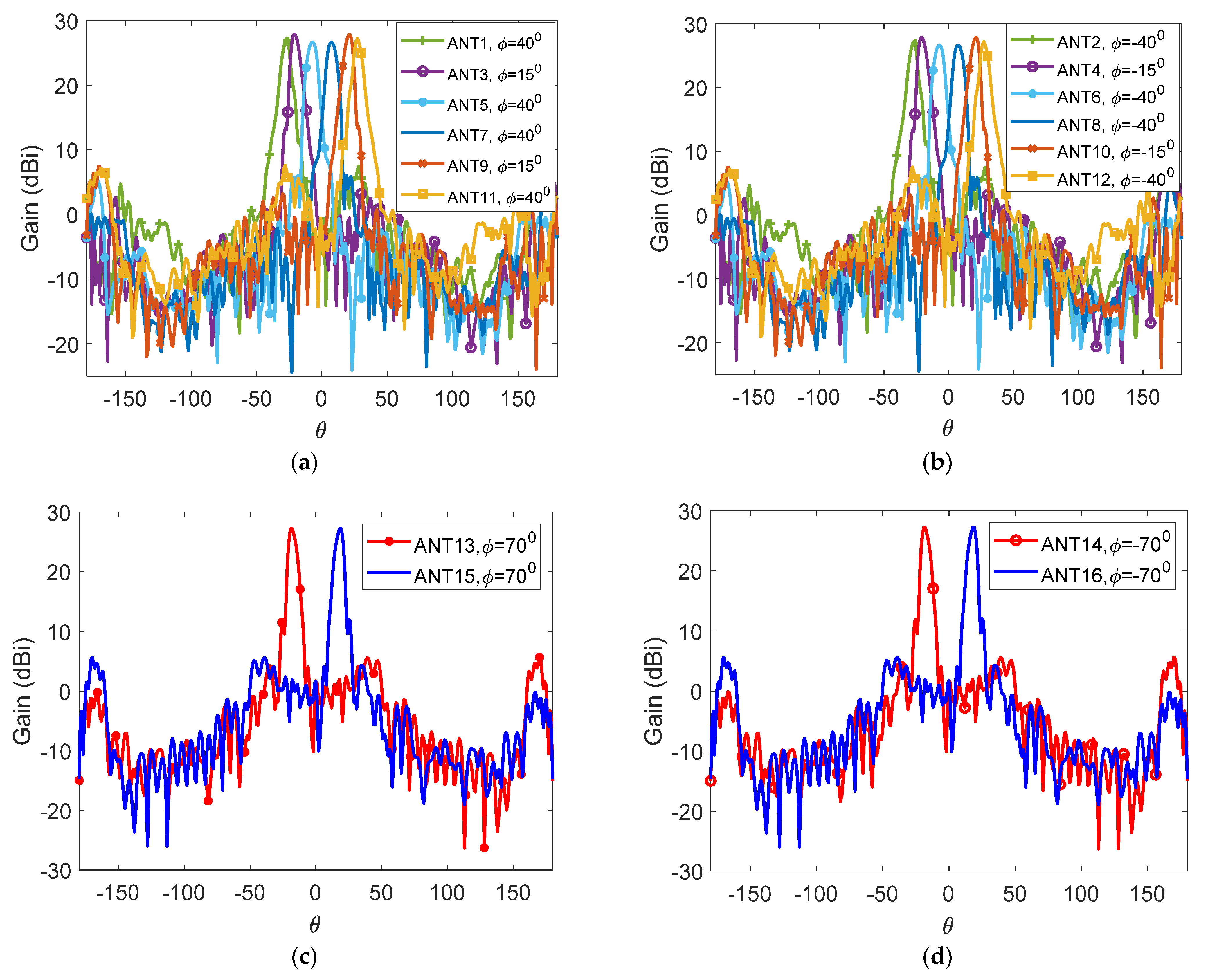
Figure 1. Physical model of a small position on the semi-spherical lens. (a) Semi-spherical lens, and (b) the effective slab of this position.
Applsci 12 00638 g001
Figure 2. The effective refractive index of the investigated slab with different t/d ratios, 0, 0.2, 0.4, 0.6, 0.8, 1, using a full-wave simulator (solid lines) and an analytical calculation (markers).
Applsci 12 00638 g002
Figure 3. The graded effective refractive index of eleven dielectric slabs, with aperture area diameter, a = 64 mm, and slab thickness, tΔ = 1 mm.
Applsci 12 00638 g003
Figure 4. (a) The designed lens 2 with the horn antenna. (b) The co-polarized radiation pattern of the horn antenna with and without a dielectric slabs-based lens using the finite integration technique (FIT) solvers in CST. The aperture area of the designed lens is a = 64.52 mm, and the horn antenna is placed at the optimized focal point (f = 50.62 mm).
Applsci 12 00638 g004
Figure 5. (a) The reflected scattering parameter and (b) cross-polarization gain.
Applsci 12 00638 g005
Figure 6. The normalized co-polarized radiation pattern of the horn antenna with a dielectric slabs-based lens using different full-wave simulators. The aperture area of the designed lens is a = 64.52 mm, and the horn antenna is placed at the optimized focal point (f = 50.62 mm).
Applsci 12 00638 g006
Figure 7. Sixteen switchable horn antennas with the designed reconfigurable dielectric lens. The diameter of the aperture area of the designed lens is a = 173 mm, the optimized focal point is f = 65.62 mm, and the number of slabs is thirteen slabs with a thickness tΔ = 2.67 mm.
Applsci 12 00638 g007
Figure 8. Co-polarized radiation patterns of sixteen switchable horn antennas with the proposed reconfigurable dielectric lens. (a) Antennas 1, 3, 5, 7, 9 and 11. (b) Antennas 2, 4, 6, 8, 10 and 12. (c) Antennas 13 and 15. (d) Antennas 14 and 16.
Applsci 12 00638 g008
Figure 9. (a) The reflected scattering parameter and (b) cross-polarization gain of four selected antennas.
Applsci 12 00638 g009
Table 1. The performance of the millimeter-wave beamforming of 16 switchable antennas.
Antenna #Gain (dBi)Sidelobe Level (dB)HPBW (Degree)θ
(Degree)
ϕ
(Degree)
ANT1, ANT227.2−20.16.2−2740, −40
ANT3, ANT427.9−20.436.6−2115, −15
ANT5, ANT626.6−21.67.8−740, −40
ANT7, ANT826.6−21.67.8740, −40
ANT9, ANT1027.9−20.436.62115, −15
ANT11, ANT1227.2−20.16.22740, −40
ANT13, ANT1427.3−21.65.9−1970, −70
ANT15, ANT1627.3−21.65.91970, −70
Table 2. Comparison of the proposed lens with other works.
ReferenceGain (dBi)Sidelobe Level (dB)HPBW
(Degree)
FrequencyDesigned LensTested
Antennas
Proposed work30−19.8628 GHzDielectric slabsCircular horn
25 to 27−20 to −21.65.9 to 7.828 GHzDielectric slabsRectangular horn
[7]29.4−22628 GHzSpherical dielectricRectangular horn
[25]15.4 to 18.9−1812 to 2060, 77 GHzDielectric flat lens with hols on concentric rings of different permittivityConical horn antenna
[26]21.25−239.69.4 GHzMetamaterials lensesRectangular horn
[27]16.9 to 21.2−3.5 to −2010.5 to 22.360 GHzDielectric flat lens with a set of concentric rings of different permittivityConical horn antenna
[28]14 to 18.4−10 to −1510 to 2060 GHzDielectric flat lens with hols on concentric rings of different permittivityArray antenna
[29]16.41530.210 GHZMetasurfaces layered lensPatch antenna
Publisher’s Note: MDPI stays neutral with regard to jurisdictional claims in published maps and institutional affiliations.

