
A Study on a New Independent Metering Valve for Hydraulic Boom Excavator


Abstract
:1. Introduction
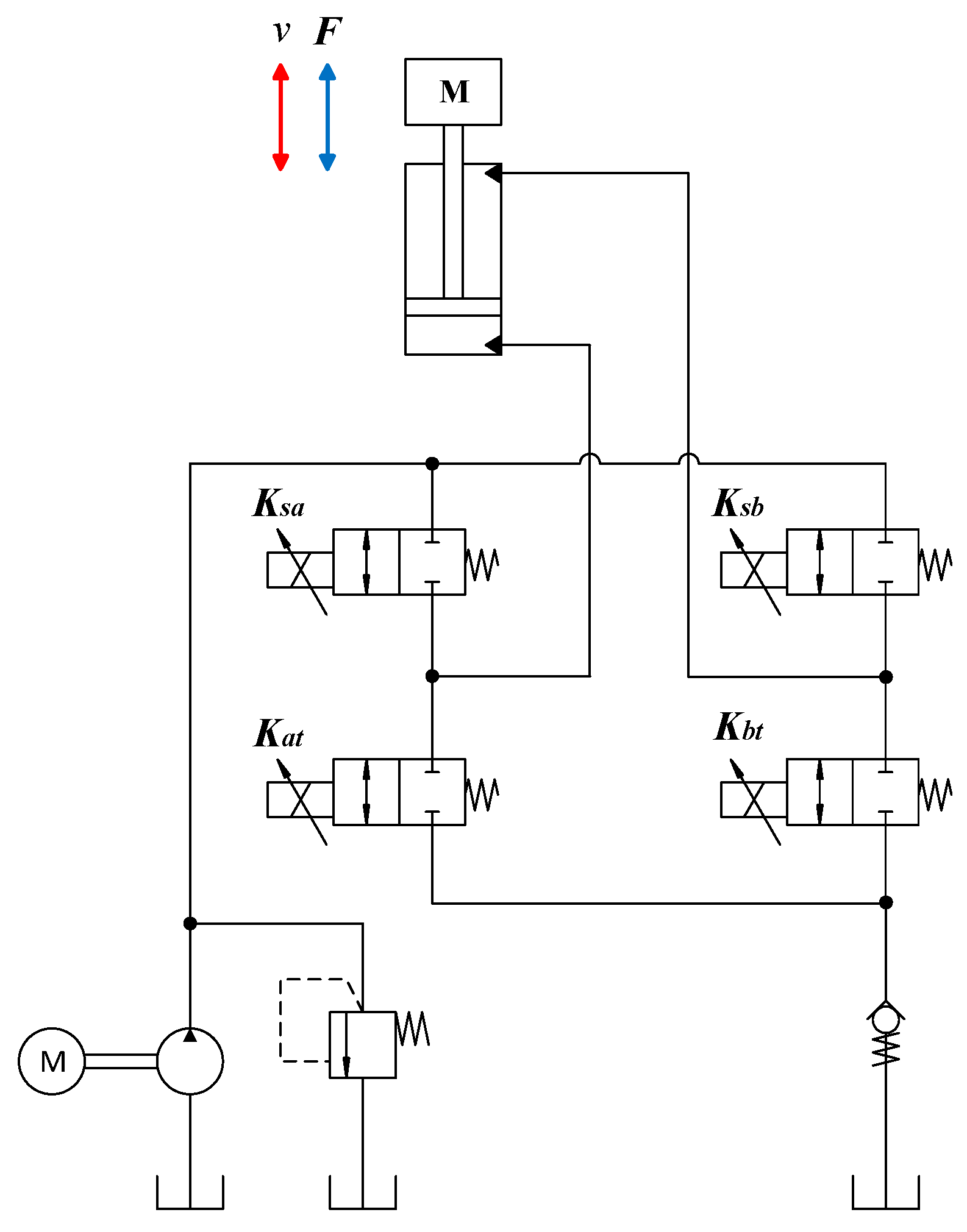
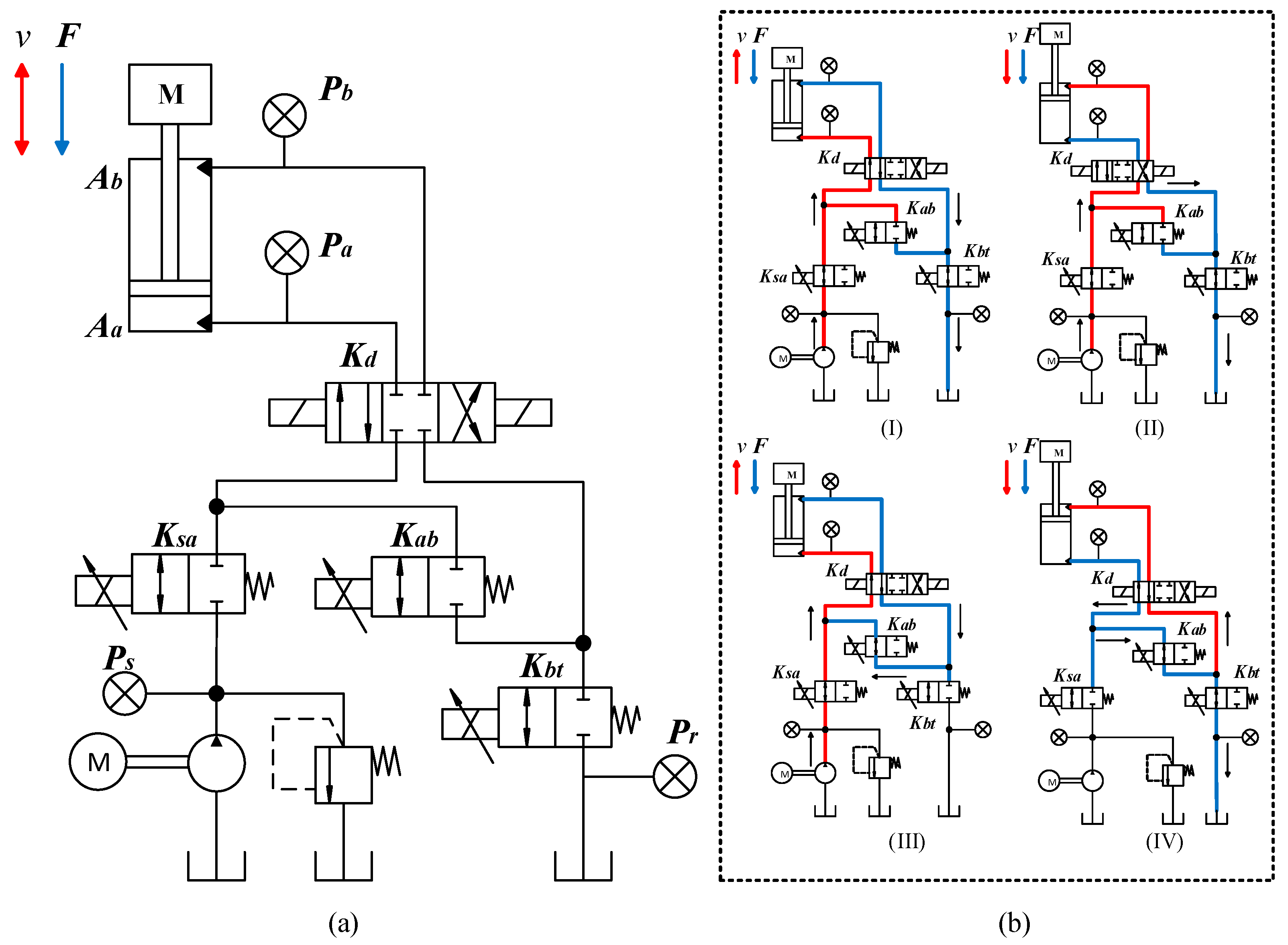
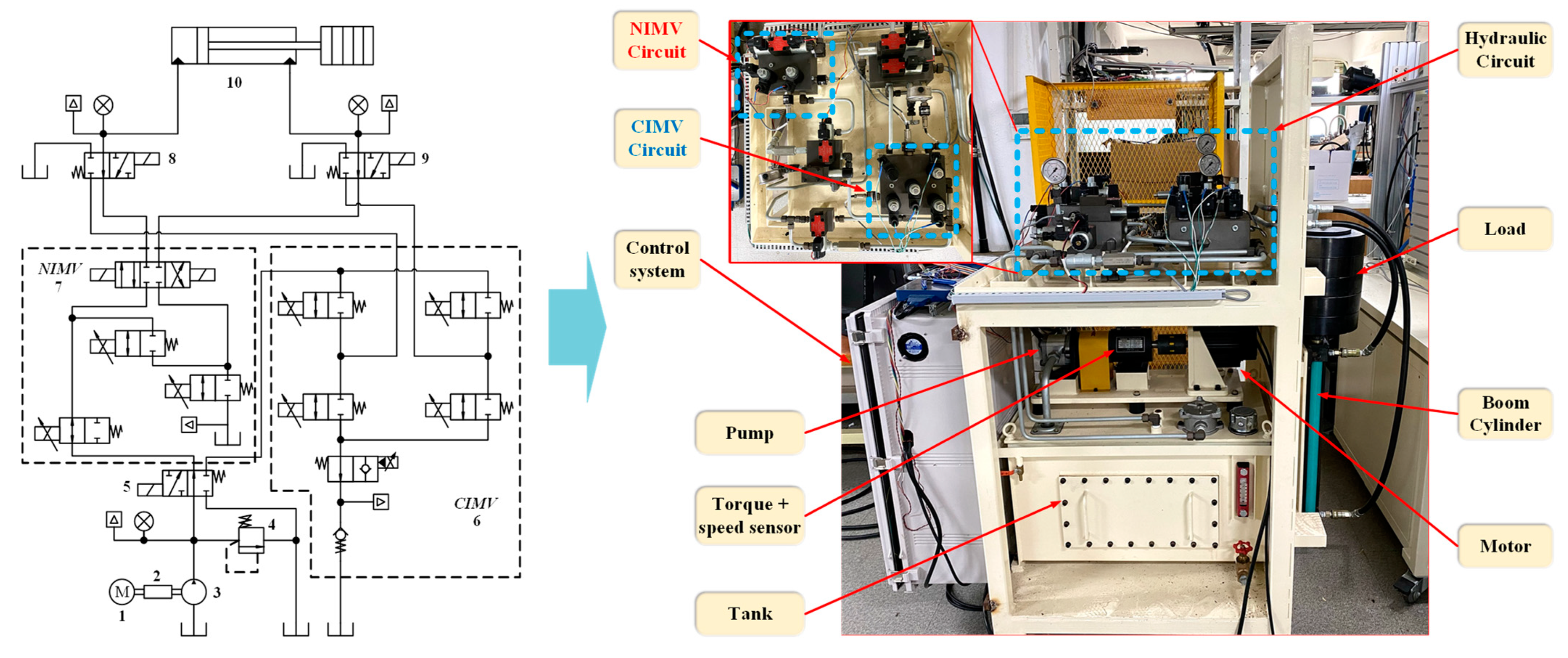
2. New Independent Metering Configuration
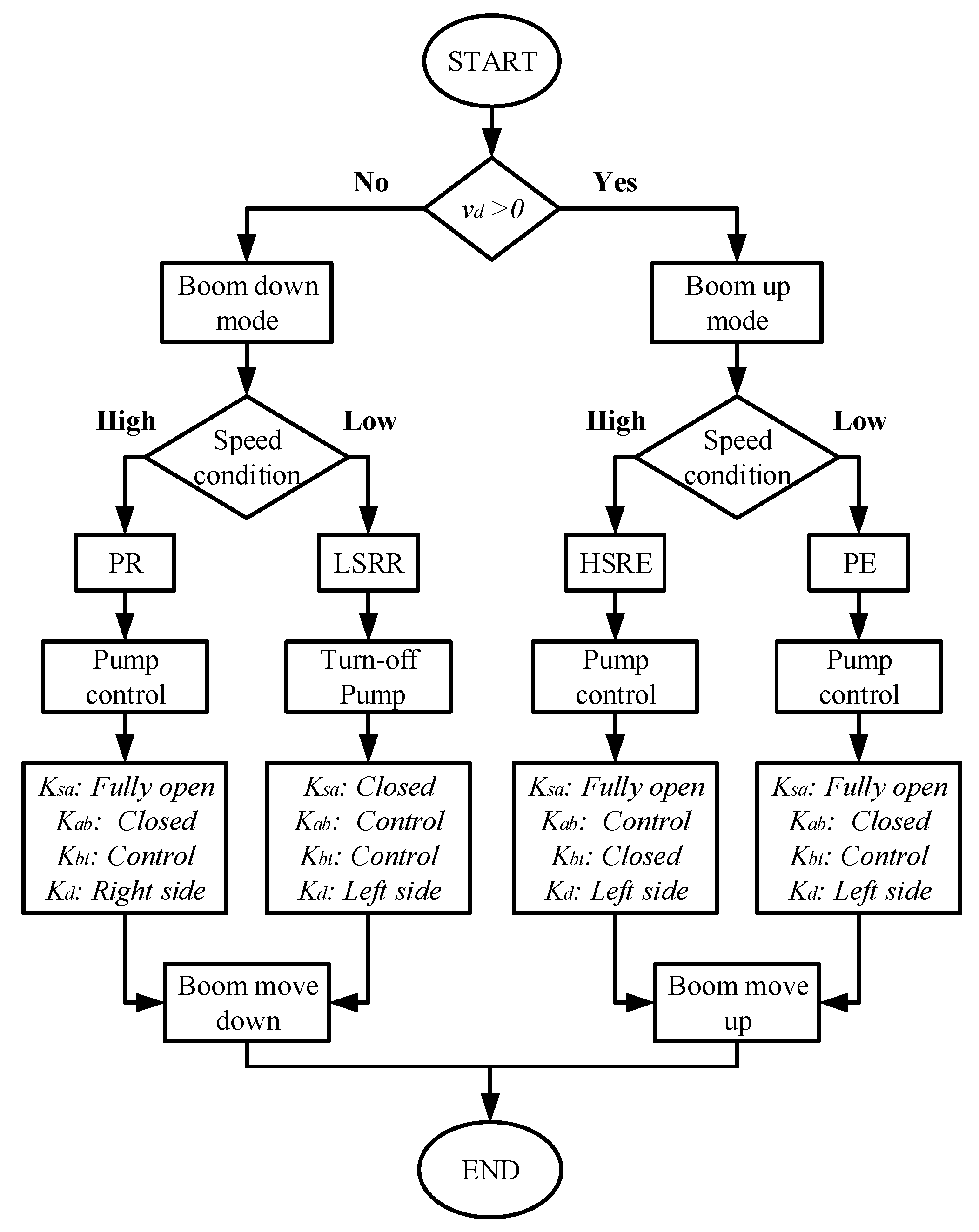
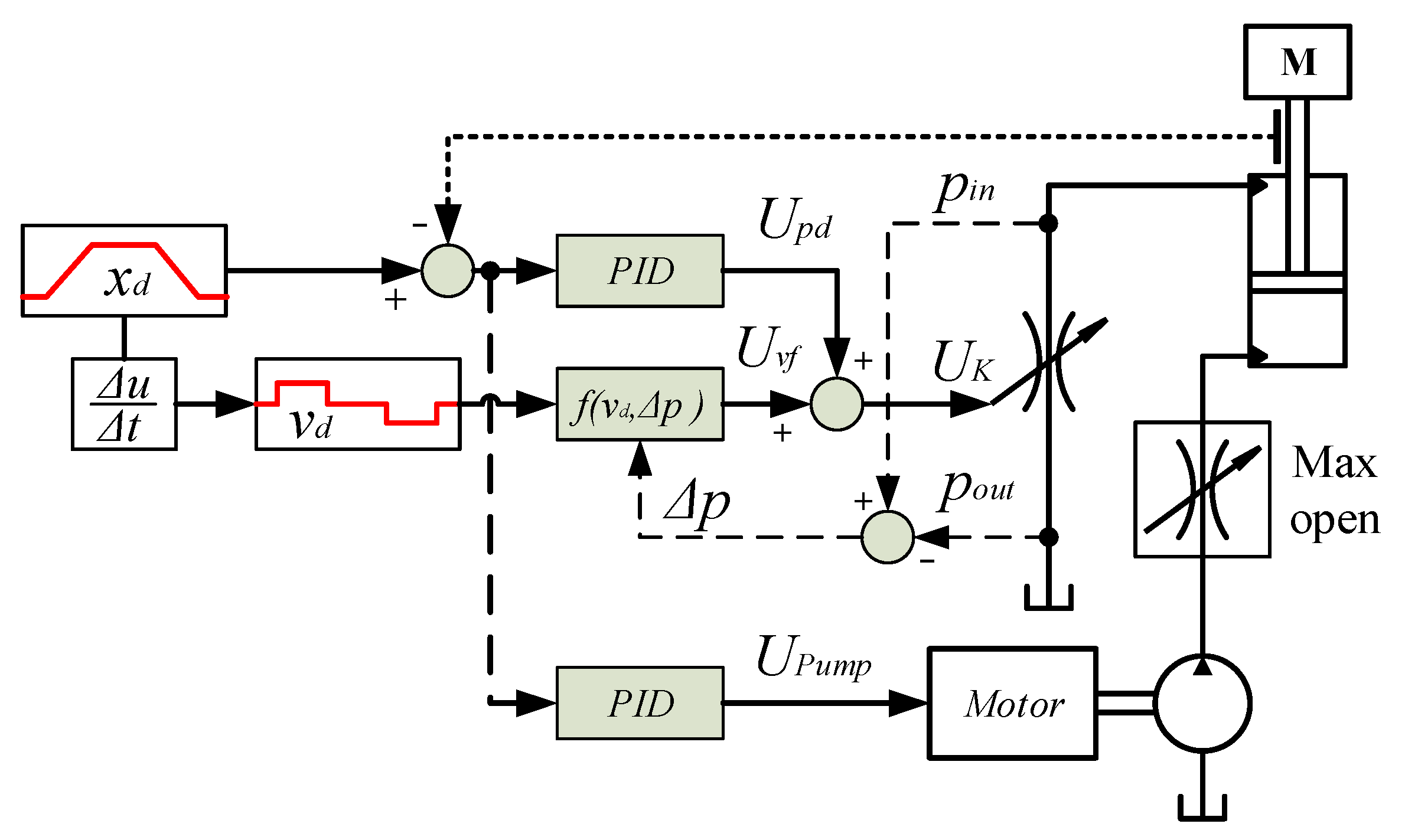
3. Control System Design
3.1. Valve Control
3.2. Pump Control
3.3. Energy Consumption
4. Experiments and Results
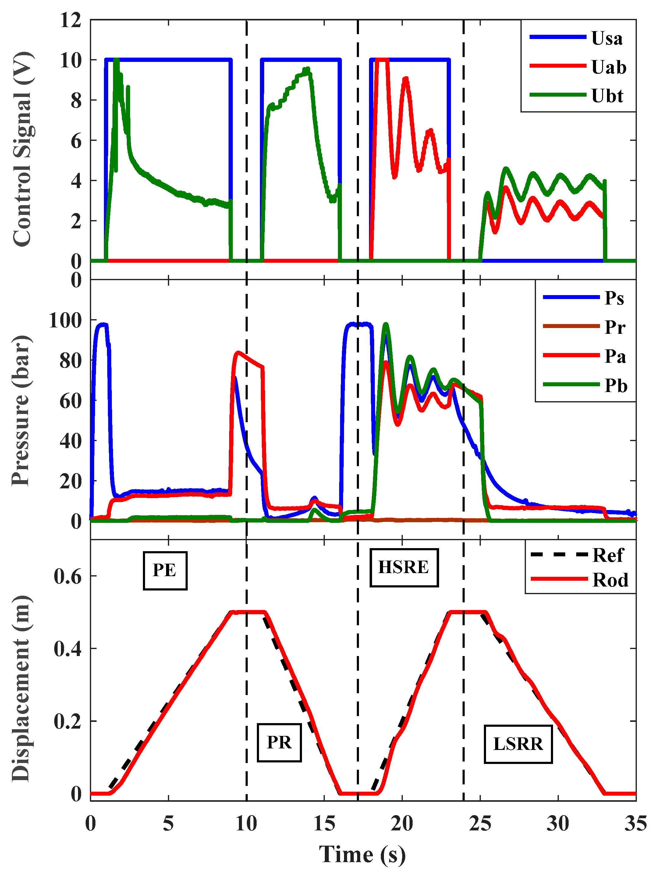
4.1. Verification with Mode Control
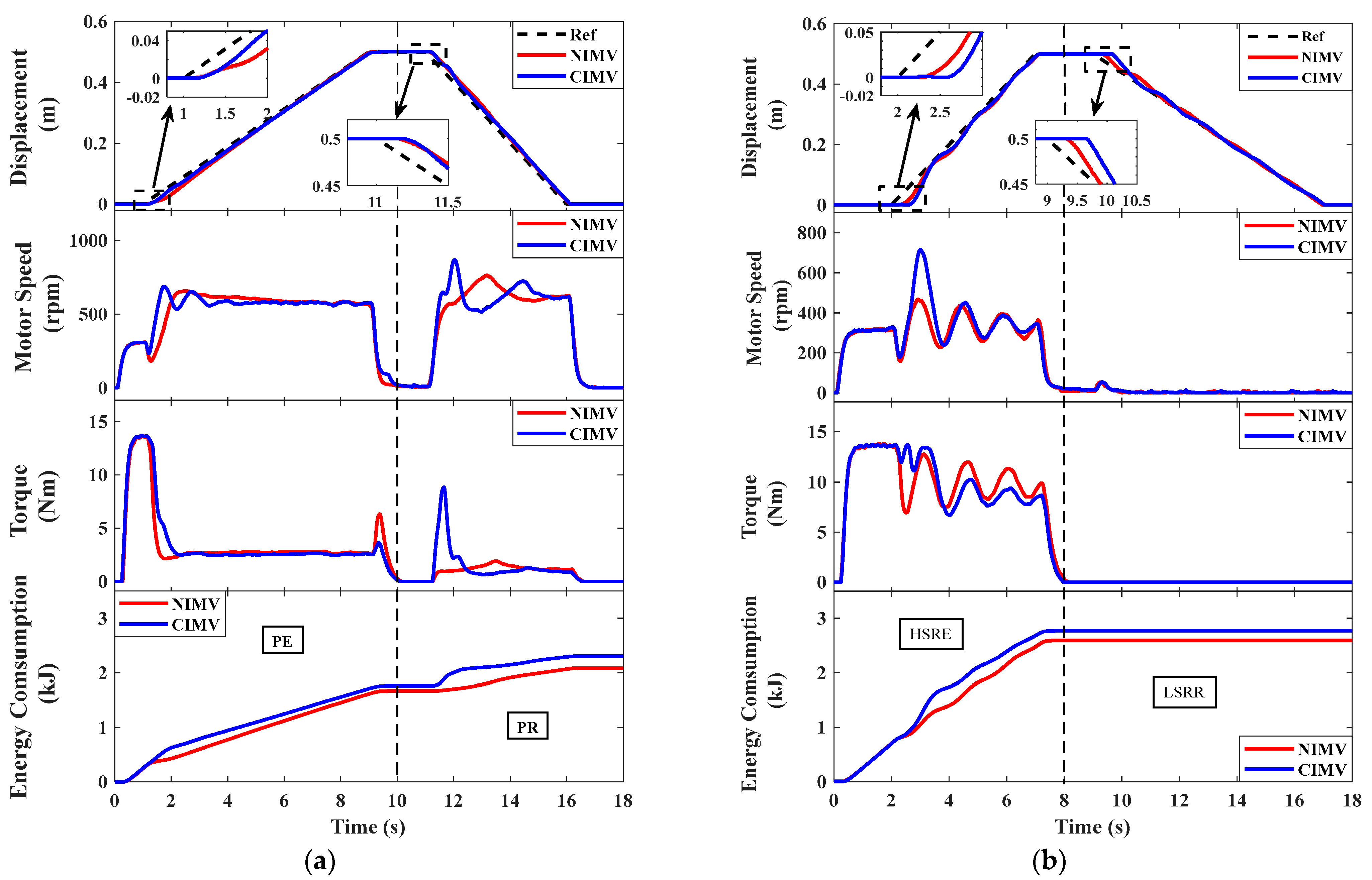
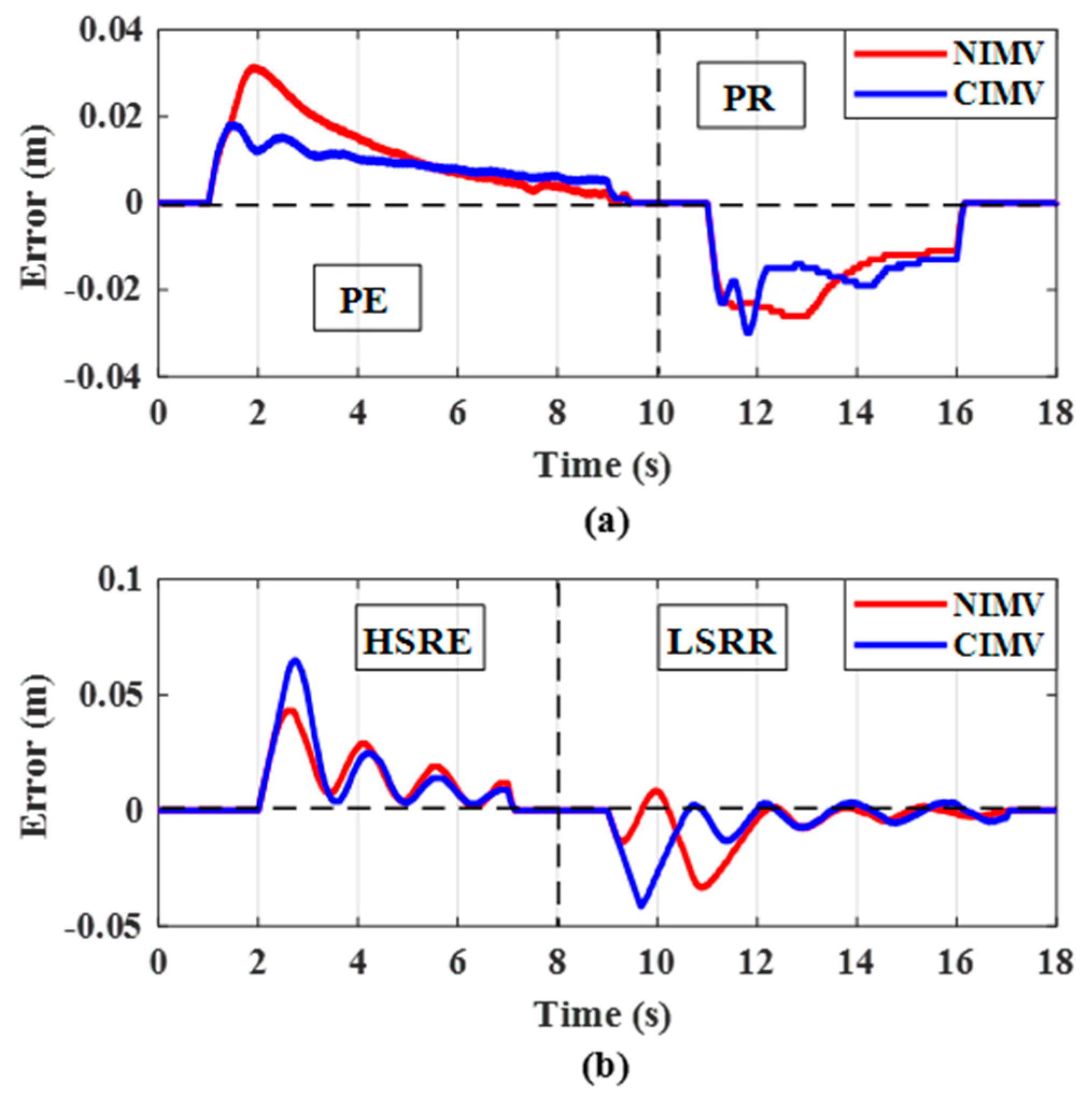
4.2. Comparison with CIMV
5. Conclusions
- The energy savings of the NIMV system was higher than the CIMV system by approximately 4% in the PE mode, 22% in the PR mode and 6.5% in the HSRE mode. The proposed system removed the use of a check valve, which is the main factor that caused energy loss in the CIMV system. Moreover, the throttling loss was reduced by the valves, which were logically connected, and are shown in the HSRE mode.
- In the proposed configuration, the cost of the system was significantly reduced by reducing one EHPV and a check valve, while ensuring the stability of the IMV system.
- Both systems applied a simple controller and achieved a high tracking performance. However, by eliminating the factors that cause losses in the system, the NIMV system could work with a higher precision and stability. Especially, the displacement tracking error of the cylinder in the NIVM system was about 0.043 m in the HSRE mode and about 0.034 m in the LSRR mode, while in the CIMV system it was around 0.065 m and 0.04 m, respectively.
Author Contributions
Funding
Institutional Review Board Statement
Informed Consent Statement
Data Availability Statement
Conflicts of Interest
References
- Jud, D.; Kerscher, S.; Wermelinger, M.; Jelavic, E.; Egli, P.; Leemann, P.; Hottiger, G.; Hutter, M. HEAP—The autonomous walking excavator. Autom. Constr. 2021, 129, 103783. [Google Scholar] [CrossRef]
- Tyni, P. Development of an Earthmoving Machinery Autonomous Excavator Development Platform. In Proceedings of the 36th International Symposium on Automation and Robotics in Construction (ISARC), Banff, AB, Canada, 21–24 May 2019. [Google Scholar]
- Shen, W.; Jiang, J.; Su, X.; Reza Karimi, H. Control strategy analysis of the hydraulic hybrid excavator. J. Frankl. Inst. 2015, 352, 541–561. [Google Scholar] [CrossRef]
- Vukovic, M.; Leifeld, R.; Murrenhoff, H. Reducing Fuel Consumption in Hydraulic Excavators—A Comprehensive Analysis. Energies 2017, 10, 687. [Google Scholar] [CrossRef] [Green Version]
- Yoon, J.I.; Truong, D.Q.; Ahn, K.K. A generation step for an electric excavator with a control strategy and verifications of energy consumption. Int. J. Precis. Eng. Manuf. 2013, 14, 755–766. [Google Scholar] [CrossRef]
- Do, T.C.; Dang, T.D.; Dinh, T.Q.; Ahn, K.K. Developments in energy regeneration technologies for hydraulic excavators: A review. Renew. Sustain. Energy Rev. 2021, 145, 111076. [Google Scholar] [CrossRef]
- Wang, T.; Wang, Q.; Lin, T. Improvement of boom control performance for hybrid hydraulic excavator with potential energy recovery. Autom. Constr. 2013, 30, 161–169. [Google Scholar] [CrossRef]
- Yu, Y.-X.; Ahn, K.K. Energy Regeneration and Reuse of Excavator Swing System with Hydraulic Accumulator. Int. J. Precis. Eng. Manuf.-Green Technol. 2020, 7, 859–873. [Google Scholar] [CrossRef]
- Yu, Y.-X.; Ahn, K.K. Improvement of Energy Regeneration for Hydraulic Excavator Swing System. Int. J. Precis. Eng. Manuf. -Green Technol. 2020, 7, 53–67. [Google Scholar] [CrossRef]
- Mirzaliev, S. A Review of Energy Saving Techniques in Mobile Hydraulic Machines. Preprints 2018, 2018100193. [Google Scholar] [CrossRef]
- Lin, T.; Chen, Q.; Ren, H.; Huang, W.; Chen, Q.; Fu, S. Review of boom potential energy regeneration technology for hydraulic construction machinery. Renew. Sustain. Energy Rev. 2017, 79, 358–371. [Google Scholar] [CrossRef]
- Liu, J.; Jiao, Z.; Xian, F.; Liu, W. Energy recovery and utilization system of excavator boom based on flow regeneration and balance theory. J. Braz. Soc. Mech. Sci. Eng. 2019, 42, 35. [Google Scholar] [CrossRef]
- Ding, R.; Zhang, J.; Xu, B. Advanced Energy Management of a Novel Independent Metering Meter-Out Control System: A Case Study of an Excavator. IEEE Access 2018, 6, 45782–45795. [Google Scholar] [CrossRef]
- Do, T.C.; Nguyen, D.G.; Dang, T.D.; Ahn, K.K. A Boom Energy Regeneration System of Hybrid Hydraulic Excavator Using Energy Conversion Components. Actuators 2021, 10, 1. [Google Scholar] [CrossRef]
- Yu, Y.; Do, T.C.; Park, Y.; Ahn, K.K. Energy saving of hybrid hydraulic excavator with innovative powertrain. Energy Convers. Manag. 2021, 244, 114447. [Google Scholar] [CrossRef]
- Ge, L.; Quan, L.; Li, Y.; Zhang, X.; Yang, J. A novel hydraulic excavator boom driving system with high efficiency and potential energy regeneration capability. Energy Convers. Manag. 2018, 166, 308–317. [Google Scholar] [CrossRef]
- Nguyen Thanh, H.; Do Tri, C.; Ahn Kyoung, K. Independent Metering Valve: A Review of Advances in Hydraulic Machinery. J. Drive Control 2020, 17, 54–71. [Google Scholar]
- Abuowda, K.; Okhotnikov, I.; Noroozi, S.; Godfrey, P.; Dupac, M. A review of electrohydraulic independent metering technology. ISA Trans. 2020, 98, 364–381. [Google Scholar] [CrossRef]
- Weber, J. Independent metering systems. Int. J. Hydromechatronics 2018, 1, 91. [Google Scholar] [CrossRef]
- Liu, K.; Gao, Y.; Tu, Z.; Lin, P. Energy-saving analysis of the independent metering system with pressure compensation for excavator’s manipulator. J. Syst. Control Eng. 2016, 230, 905–920. [Google Scholar] [CrossRef]
- Shenouda, A.; Book, W. Energy Saving Analysis Using a Four-Valve Independent Metering Configuration Controlling a Hydraulic Cylinder. In SAE Technical Paper; SAE International: Warrendale, PA, USA, 2005. [Google Scholar]
- Liu, K.; Gao, Y.; Tu, Z. Energy saving potential of load sensing system with hydro-mechanical pressure compensation and independent metering. Int. J. Fluid Power 2016, 17, 173–186. [Google Scholar] [CrossRef]
- Lyu, L.; Chen, Z.; Yao, B. Development of Pump and Valves Combined Hydraulic System for Both High Tracking Precision and High Energy Efficiency. IEEE Trans. Ind. Electron. 2019, 66, 7189–7198. [Google Scholar] [CrossRef]
- Lyu, L.; Chen, Z.; Yao, B. Energy Saving Motion Control of Independent Metering Valves and Pump Combined Hydraulic System. IEEE/ASME Trans. Mechatron. 2019, 24, 1909–1920. [Google Scholar] [CrossRef]
- Abuowda, K.; Noroozi, S.; Dupac, M.; Godfrey, P. Algorithm Design for the Novel Mechatronics Electro-Hydraulic Driving System: Micro-Independent Metering. In Proceedings of the 2019 IEEE International Conference on Mechatronics (ICM), Ilmenau, Germany, 18–20 March 2019; Volume 1, pp. 7–12. [Google Scholar]
- Abuowda, K.; Dupac, M.; Noroozi, S.; Godfrey, P. Mathematical-based control method and performance analysis of a novel hydromechatronics driving system micro-independent metering. Math. Methods Appl. Sci. 2020. [Google Scholar] [CrossRef]
- Tabor, K.A. Optimal Velocity Control and Cavitation Prevention of a Hydraulic Actuator Using Four Valve Independent Metering. In SAE Technical Paper; SAE International: Warrendale, PA, USA, 2005. [Google Scholar]
- Choi, K.; Seo, J.; Nam, Y.; Kim, K.U. Energy-saving in excavators with application of independent metering valve. J. Mech. Sci. Technol. 2015, 29, 387–395. [Google Scholar] [CrossRef]
- Ding, R.; Xu, B.; Zhang, J.; Cheng, M. Self-tuning pressure-feedback control by pole placement for vibration reduction of excavator with independent metering fluid power system. Mech. Syst. Signal Process. 2017, 92, 86–106. [Google Scholar] [CrossRef]
- Lyu, L.; Chen, Z.; Yao, B. High Precision Energy Saving Motion Control of Hydraulic Cylinder Based on Integration of Valves and Pump. In Proceedings of the BATH/ASME 2018 Symposium on Fluid Power and Motion Control, Bath, UK, 12–14 September 2018; 2018; p. V001T01A019. [Google Scholar]
- Helian, B.; Chen, Z.; Yao, B. Precision Motion Control of a Servomotor-Pump Direct-Drive Electrohydraulic System With a Nonlinear Pump Flow Mapping. IEEE Trans. Ind. Electron. 2020, 67, 8638–8648. [Google Scholar] [CrossRef]
- Ding, R.; Cheng, M.; Zheng, S.; Xu, B. Sensor-Fault-Tolerant Operation for the Independent Metering Control System. IEEE/ASME Trans. Mechatron. 2020, 26, 2558–2569. [Google Scholar] [CrossRef]
- Xu, B.; Ding, R.; Zhang, J.; Cheng, M.; Sun, T. Pump/valves coordinate control of the independent metering system for mobile machinery. Autom. Constr. 2015, 57, 98–111. [Google Scholar] [CrossRef]
- Ding, R.; Xu, B.; Zhang, J.; Cheng, M. Bumpless mode switch of independent metering fluid power system for mobile machinery. Autom. Constr. 2016, 68, 52–64. [Google Scholar] [CrossRef]
- Shi, J.; Quan, L.; Zhang, X.; Xiong, X. Electro-hydraulic velocity and position control based on independent metering valve control in mobile construction equipment. Autom. Constr. 2018, 94, 73–84. [Google Scholar] [CrossRef]
- Zhang, X.; Qiao, S.; Quan, L.; Ge, L. Velocity and Position Hybrid Control for Excavator Boom Based on Independent Metering System. IEEE Access 2019, 7, 71999–72011. [Google Scholar] [CrossRef]
- Ahamad, M.; Dinh, Q.-T.; Nahian, S.A.; Ahn, K.-K. Development of a New Generation of Independent Metering Valve Circuit for Hydraulic Boom Cylinder Control. Int. J. Autom. Technol. 2015, 9, 143–152. [Google Scholar] [CrossRef]


| Metering Mode | Ksa | Kab | Kbt | Kd |
|---|---|---|---|---|
| PE | Open | Closed | Open | Left |
| PR | Open | Closed | Open | Right |
| HSRE | Open | Open | Closed | Left |
| LSRR | Closed | Open | Open | Left |
| Parameters | Specification | Value |
|---|---|---|
| Cylinder (D140H-LA40B-N500) | Piston diameter × rod diameter × length of stroke | 40 mm × 20 mm× 500 mm |
| Gear pump (SAP20-8.0) | Pump displacement | 8.3 cc/rev |
| Max. speed | 3500 rev/min | |
| Max. speed control | 1500 rev/min | |
| Relief valve (VPN1-06-MP-32S) | Cracking pressure | 100 bar |
| EHPV (SP10-24) | Max. flow rate | 26.5 L/min |
| Max. operating pressure | 207 bar | |
| Check valve (VJ3-10-005-G1) | Cracking pressure | 0.5 bar |
| Directional valve (SP10-21) | Max. flow rate | 60 L/min |
| Max. operating pressure | 250 bar |
| Mode | NIMV | CIMV | Energy-Saving |
|---|---|---|---|
| PE | 1.69 kJ | 1.76 kJ | % |
| PR | 0.42 kJ | 0.54 kJ | % |
| HSRE | 2.59 kJ | 2.77 kJ | 6.5% |
Publisher’s Note: MDPI stays neutral with regard to jurisdictional claims in published maps and institutional affiliations. |
© 2022 by the authors. Licensee MDPI, Basel, Switzerland. This article is an open access article distributed under the terms and conditions of the Creative Commons Attribution (CC BY) license (https://creativecommons.org/licenses/by/4.0/).
Share and Cite
Nguyen, T.-H.; Do, T.-C.; Ahn, K.-K. A Study on a New Independent Metering Valve for Hydraulic Boom Excavator. Appl. Sci. 2022, 12, 605. https://doi.org/10.3390/app12020605
Nguyen T-H, Do T-C, Ahn K-K. A Study on a New Independent Metering Valve for Hydraulic Boom Excavator. Applied Sciences. 2022; 12(2):605. https://doi.org/10.3390/app12020605
Chicago/Turabian StyleNguyen, Thanh-Ha, Tri-Cuong Do, and Kyoung-Kwan Ahn. 2022. "A Study on a New Independent Metering Valve for Hydraulic Boom Excavator" Applied Sciences 12, no. 2: 605. https://doi.org/10.3390/app12020605
APA StyleNguyen, T.-H., Do, T.-C., & Ahn, K.-K. (2022). A Study on a New Independent Metering Valve for Hydraulic Boom Excavator. Applied Sciences, 12(2), 605. https://doi.org/10.3390/app12020605