

Investigation of the Mechanical Properties of Additively Manufactured Metal Parts with Different Relative Densities


Abstract
1. Introduction
2. Materials and Methods
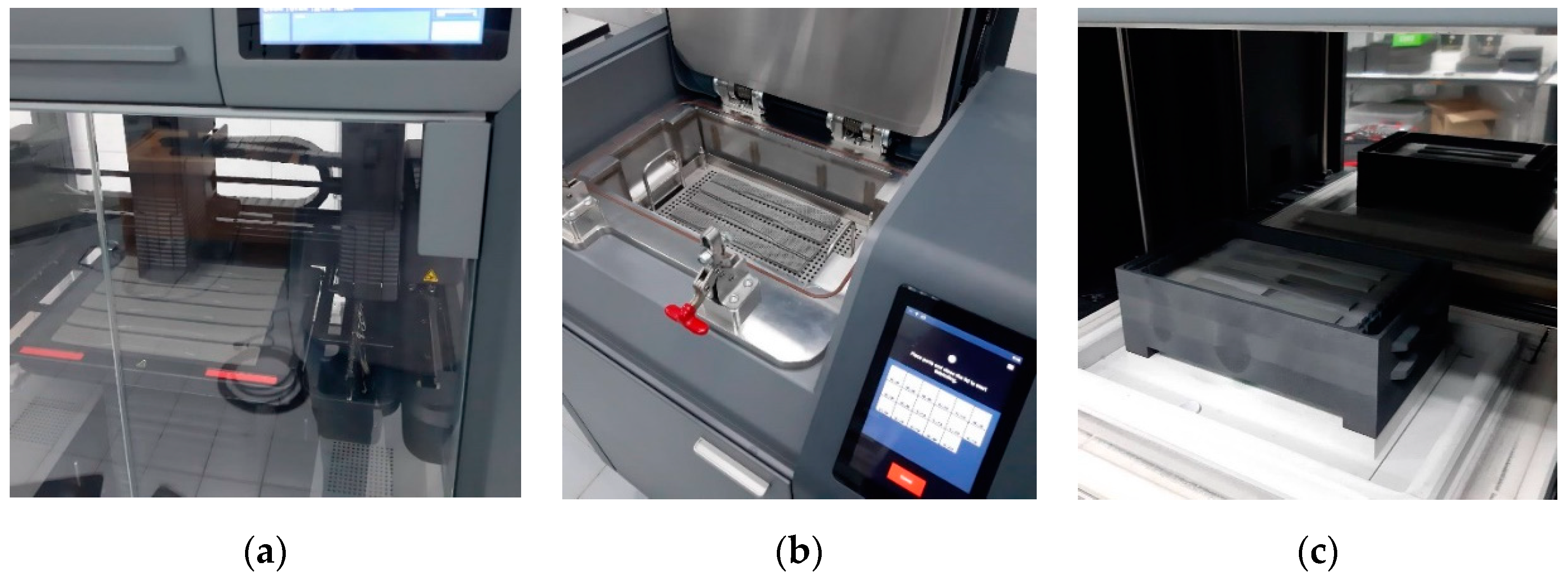
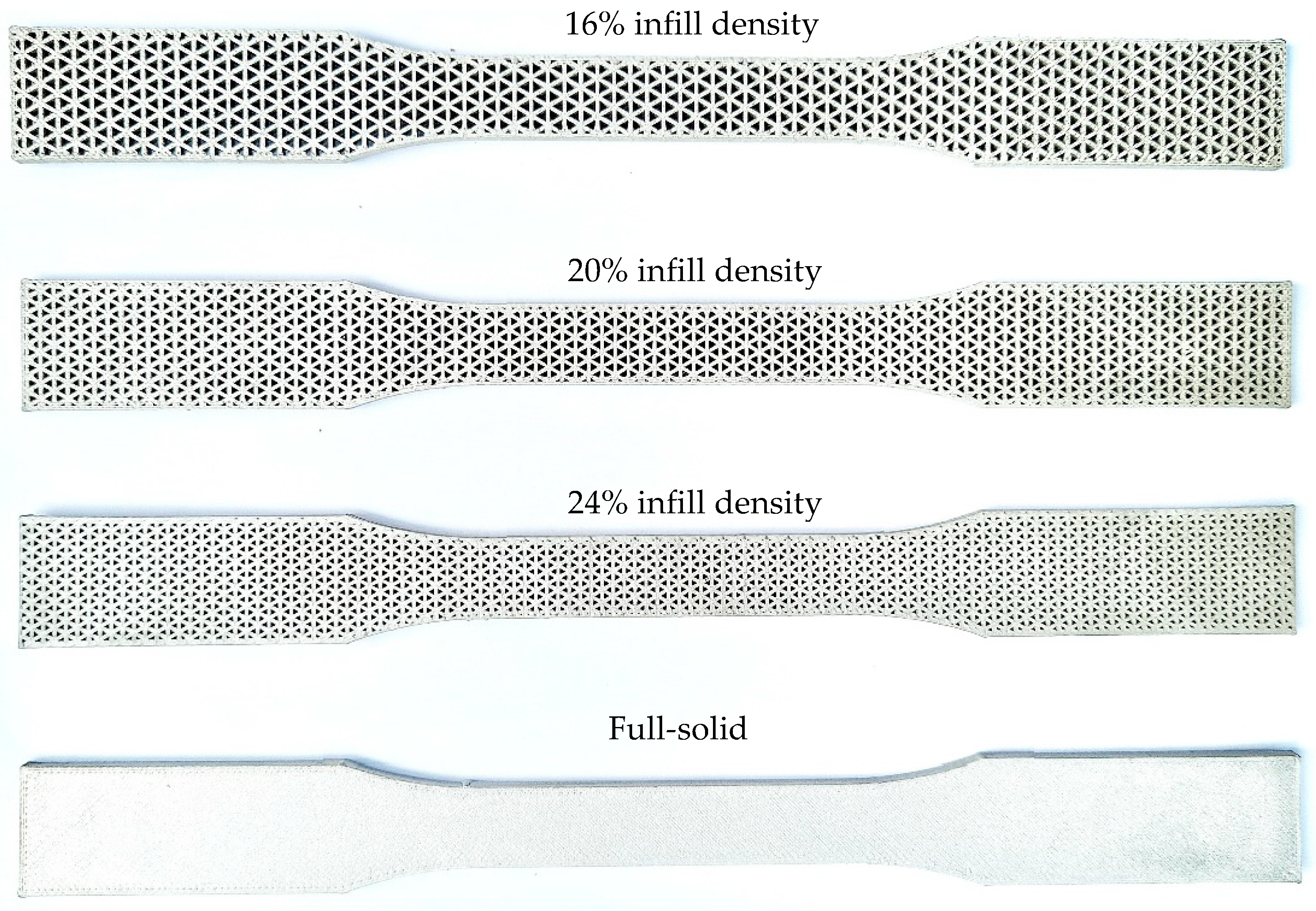
2.1. Specimen Preparation
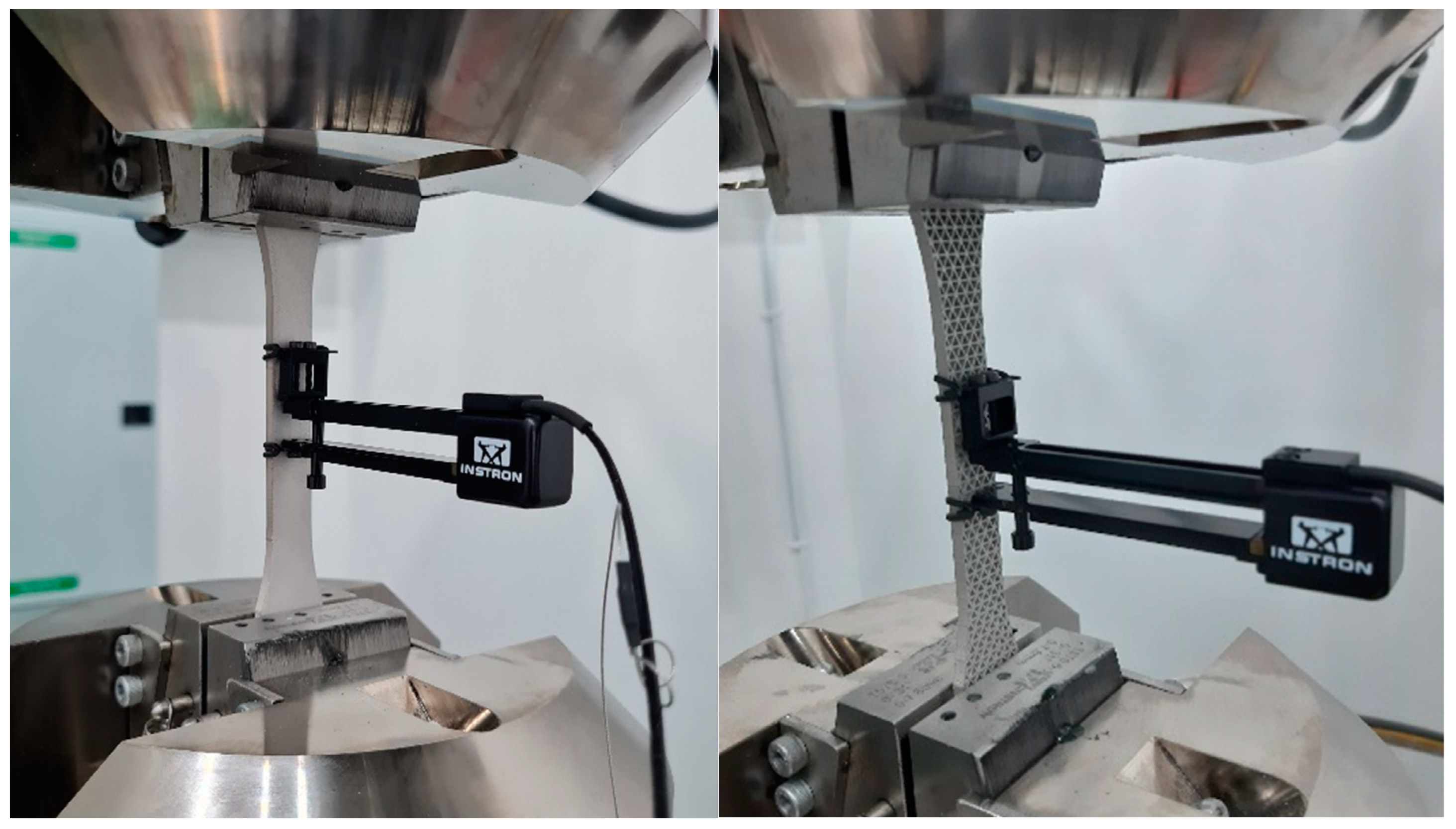
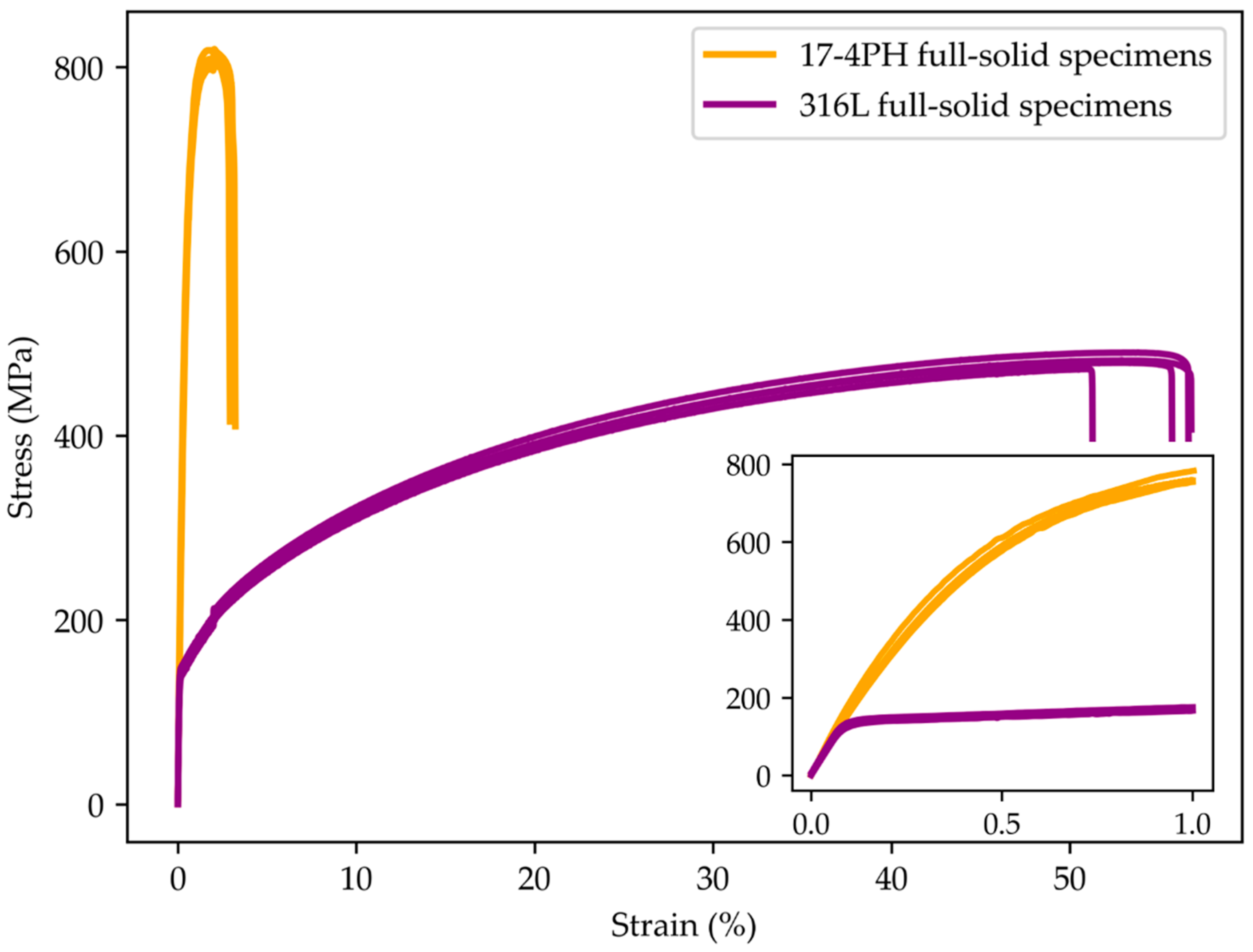
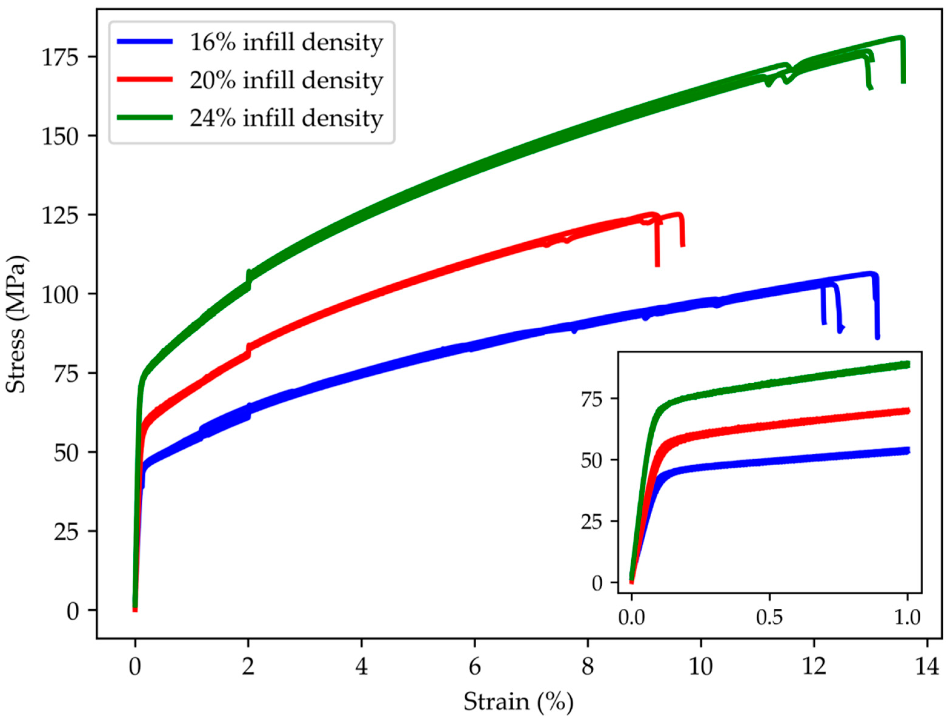
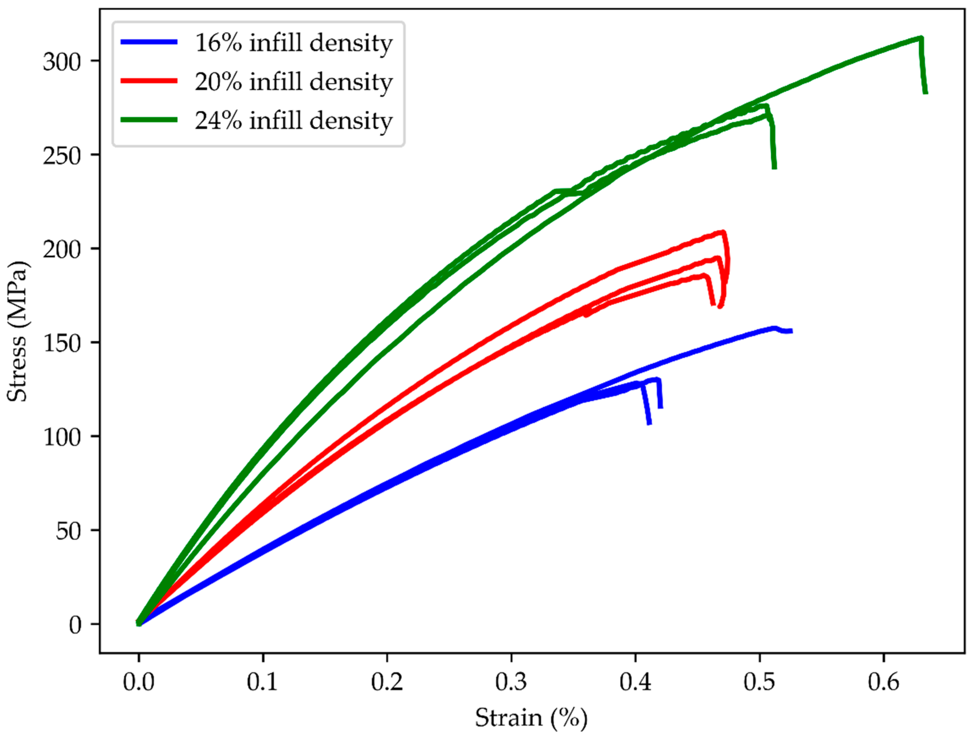
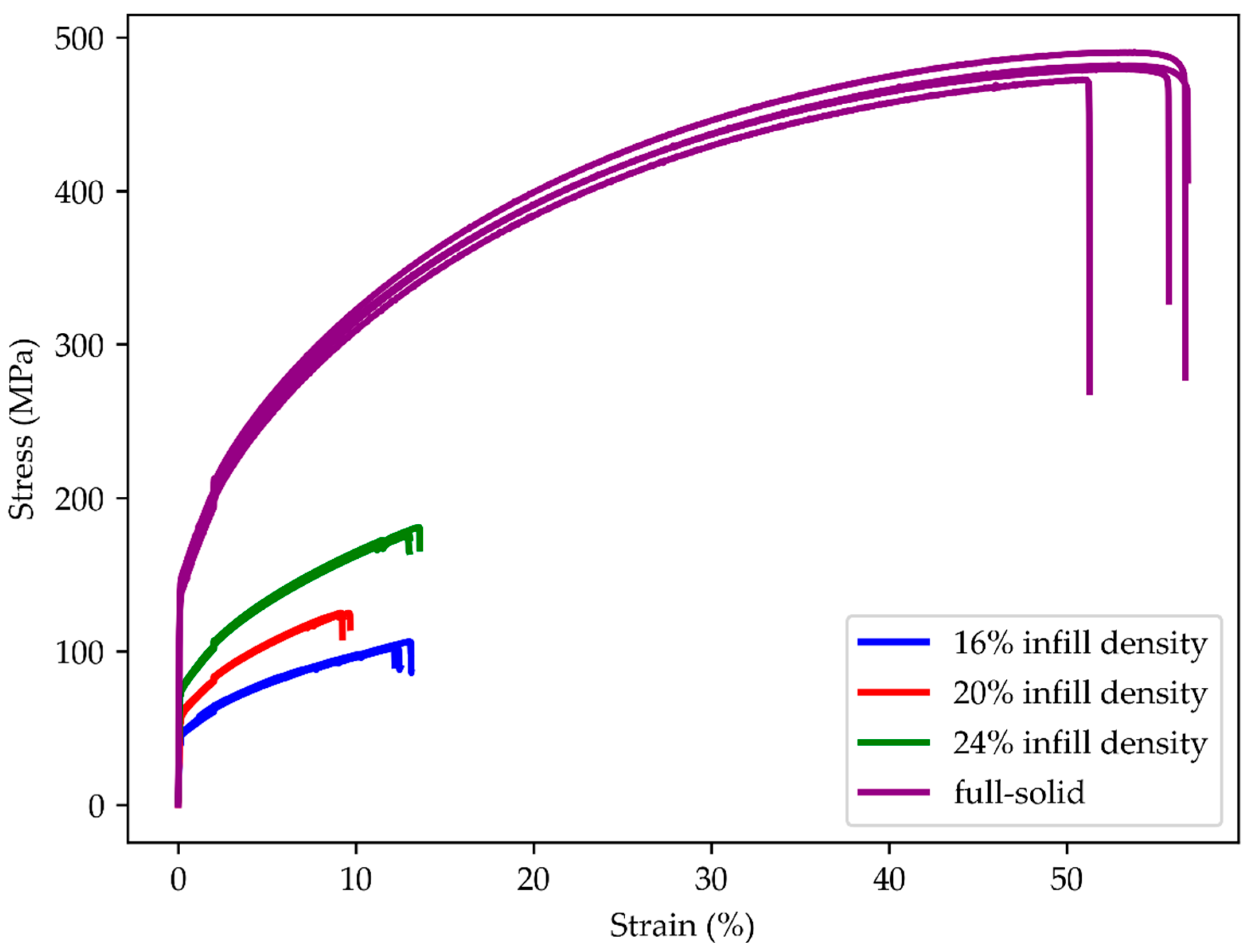
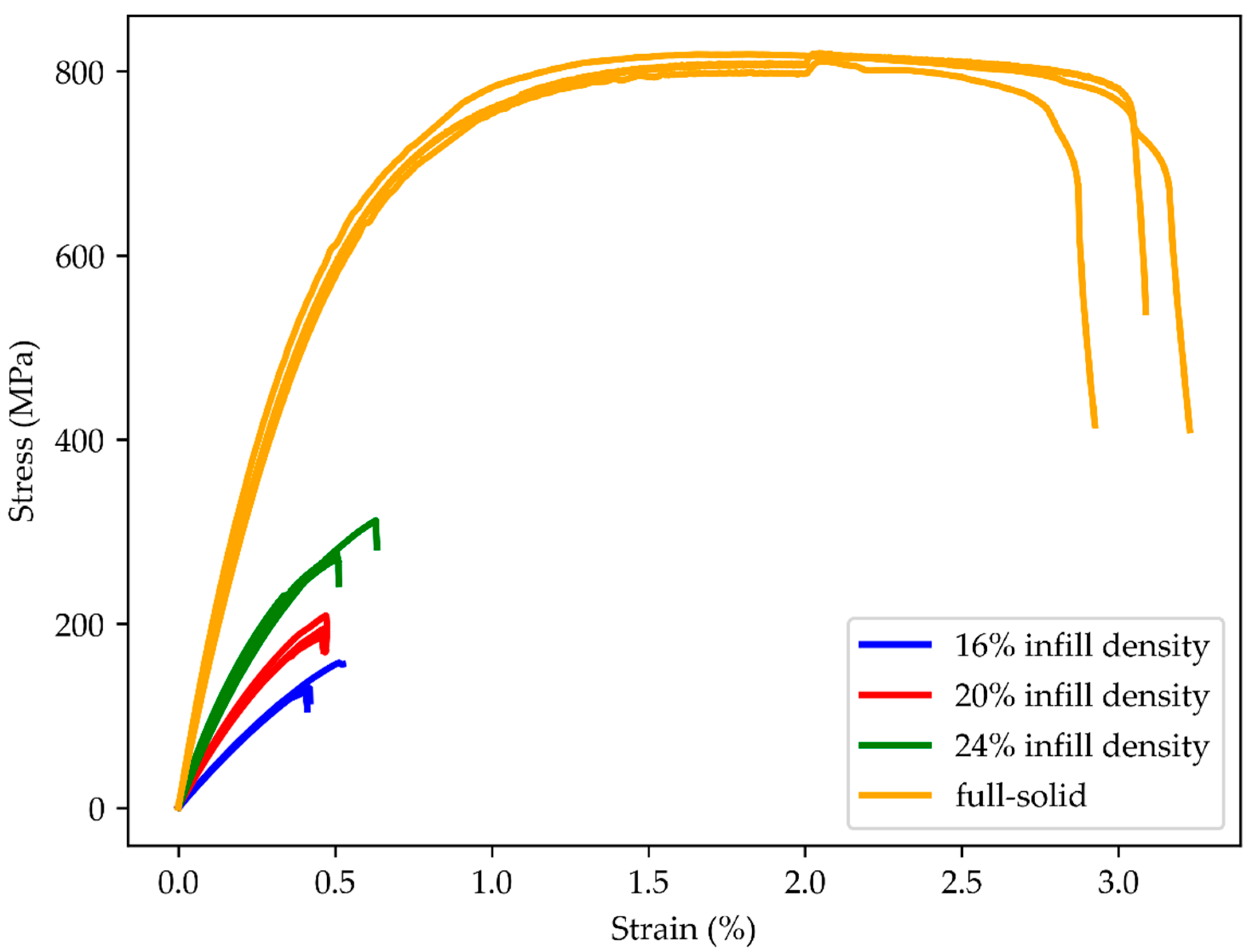
2.2. Tensile Test
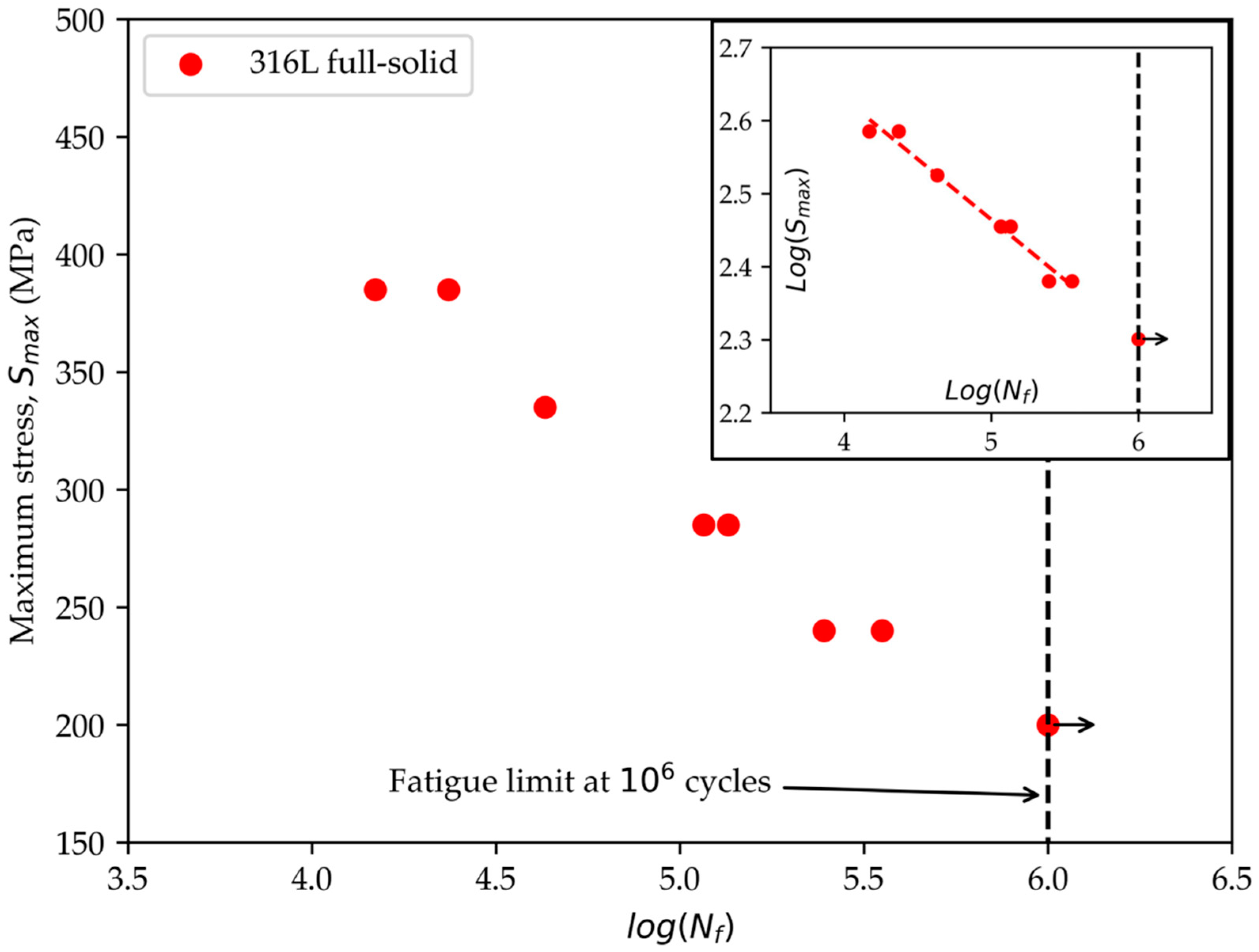
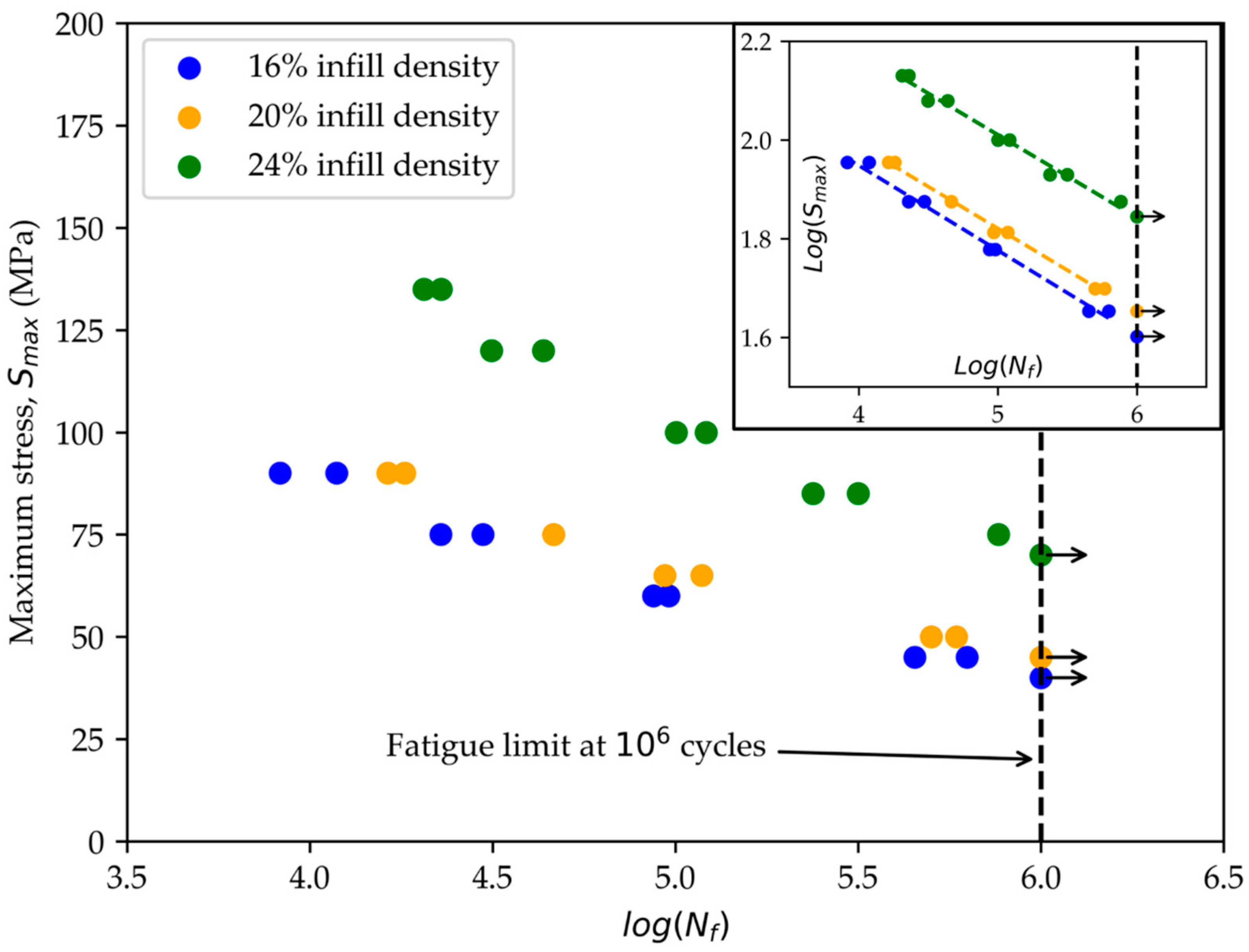
2.3. Fatigue Test
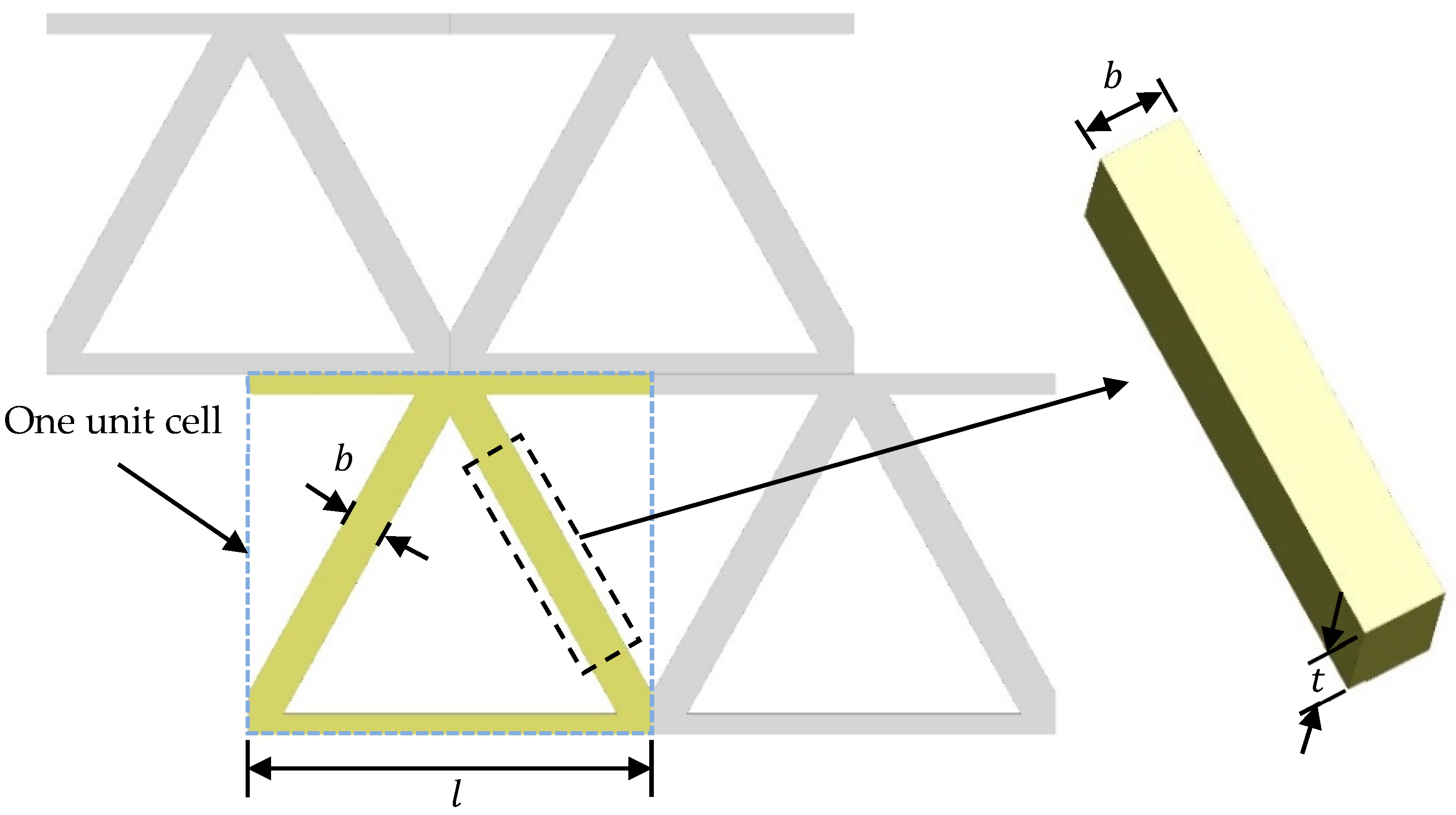
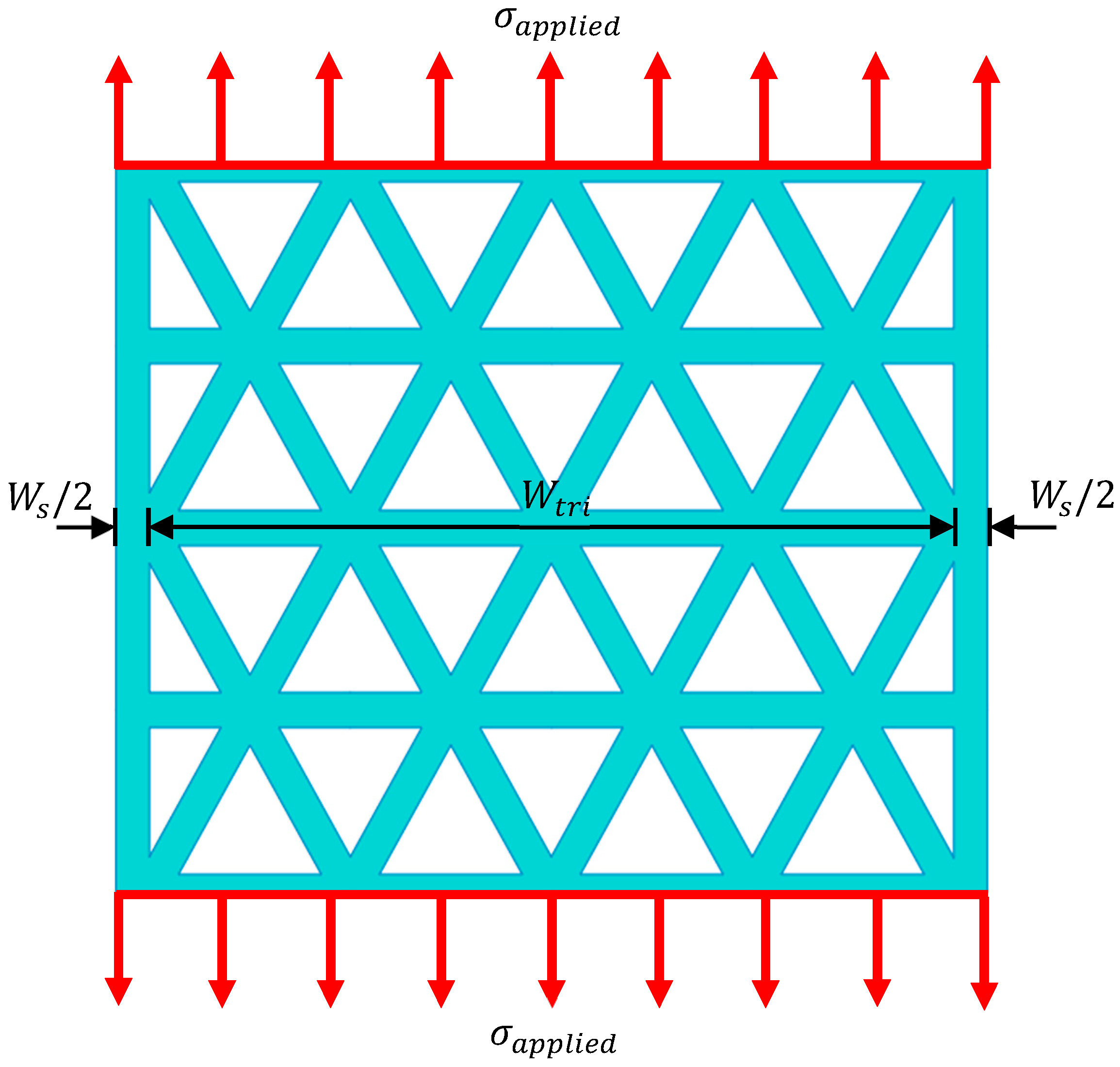
2.4. Analytical Method
2.5. Weight Efficiency
3. Results and Discussion
4. Conclusions
Author Contributions
Funding
Institutional Review Board Statement
Informed Consent Statement
Data Availability Statement
Acknowledgments
Conflicts of Interest
References
- Abduo, J.; Lyons, K.; Bennamoun, M. Trends in computer-aided manufacturing in prosthodontics: A review of the available streams. Int. J. Dent. 2014, 2014, 783948. [Google Scholar] [CrossRef] [PubMed]
- Jandyal, A.; Chaturvedi, I.; Wazir, I.; Raina, A.; Ul Haq, M.I. 3D printing—A review of processes, materials and applications in industry 4.0. Sustain. Oper. Comput. 2022, 3, 33–42. [Google Scholar] [CrossRef]
- Subeshan, B.; Baddam, Y.; Asmatulu, E. Current progress of 4D-printing technology. Prog. Addit. Manuf. 2021, 6, 495–516. [Google Scholar] [CrossRef]
- Jia, D.; Li, F.; Zhang, Y. 3D-printing process design of lattice compressor impeller based on residual stress and deformation. Sci. Rep. 2020, 10, 600. [Google Scholar] [CrossRef] [PubMed]
- Vasques, C.M.A.; Gonçalves, F.C.; Cavadas, A.M.S. Manufacturing and Testing of 3D-Printed Polymer Isogrid Lattice Cylindrical Shell Structures. In Proceedings of the 2nd International Electronic Conference on Applied Sciences, Online, 15–21 October 2021. [Google Scholar]
- Blakey-Milner, B.; Gradl, P.; Snedden, G.; Brooks, M.; Pitot, J.; Lopez, E.; Leary, M.; Berto, F.; du Plessis, A. Metal additive manufacturing in aerospace: A review. Mater. Des. 2021, 209, 110008. [Google Scholar] [CrossRef]
- Khorasani, M.; Ghasemi, A.; Rolfe, B.; Gibson, I. Additive manufacturing a powerful tool for the aerospace industry. Rapid Prototyp. J. 2021, 28, 1355–2546. [Google Scholar] [CrossRef]
- Adamczak, S.; Bochnia, J.; Kaczmarska, B. An Analysis of Tensile Test Results to Assess the Innovation Risk for an Additive Manufacturing Technology. Metrol. Meas. Syst. 2015, 22, 127–138. [Google Scholar] [CrossRef]
- Hsueh, M.H.; Lai, C.J.; Liu, K.Y.; Chung, C.F.; Wang, S.H.; Pan, C.Y.; Huang, W.C.; Hsieh, C.H.; Zeng, Y.S. Effects of Printing Temperature and Filling Percentage on the Mechanical Behavior of Fused Deposition Molding Technology Components for 3D Printing. Polymers 2021, 13, 2910. [Google Scholar] [CrossRef]
- Johnson, G.A.; French, J.J. Evaluation of infill effect on mechanical properties of consumer 3D printing materials. Adv. Technol. Innov. 2018, 3, 179. [Google Scholar]
- Khan, S.A.; Siddiqui, B.A.; Fahad, M.; Khan, M.A. Evaluation of the Effect of Infill Pattern on Mechanical Stregnth of Additively Manufactured Specimen. Mater. Sci. Forum 2017, 887, 128–132. [Google Scholar] [CrossRef]
- Letcher, T.; Rankouhi, B.; Javadpour, S. Experimental Study of Mechanical Properties of Additively Manufactured ABS Plastic as a Function of Layer Parameters. In Proceedings of the ASME 2015 International Mechanical Engineering Congress and Exposition, Houston, TX, USA, 13–19 November 2019. [Google Scholar]
- Caminero, M.Á.; Gutiérrez, A.R.; Chacón, J.M.; García-Plaza, E.; Núñez, P.J. Effects of fused filament fabrication parameters on the manufacturing of 316L stainless-steel components: Geometric and mechanical properties. Rapid Prototyp. J. 2022; ahead-of-print. [Google Scholar] [CrossRef]
- Suwanpreecha, C.; Manonukul, A. On the build orientation effect in as-printed and as-sintered bending properties of 17-4PH alloy fabricated by metal fused filament fabrication. Rapid Prototyp. J. 2022, 28, 1355–2546. [Google Scholar] [CrossRef]
- Gasparetto, V.; ElSayed, M. Multiscale Modelling and Mechanical Anisotropy of Periodic Cellular Solids with Rigid-Jointed Truss-Like Microscopic Architecture. Appl. Mech. 2021, 2, 331–355. [Google Scholar] [CrossRef]
- Gu, H.; Pavier, M.; Shterenlikht, A. Experimental study of modulus, strength and toughness of 2D triangular lattices. Int. J. Solids Struct. 2018, 152–153, 207–216. [Google Scholar] [CrossRef]
- Wang, A.J.; McDowell, D.L. In-Plane Stiffness and Yield Strength of Periodic Metal Honeycombs. J. Eng. Mater. Technol. 2004, 126, 137–156. [Google Scholar] [CrossRef]
- Theerakittayakorn, K.; Suttakul, P.; Sam, P.; Nanakorn, P. Design of frame-like periodic solids for isotropic symmetry by member sizing. J. Mech. 2017, 33, 41–54. [Google Scholar] [CrossRef]
- Sam, P.; Nanakorn, P.; Theerakittayakorn, K.; Suttakul, P. Closed-form effective elastic constants of frame-like periodic cellular solids by a symbolic object-oriented finite element program. Int. J. Mech. Mater. Des. 2016, 13, 363–383. [Google Scholar] [CrossRef]
- Somnic, J.; Jo, B.W. Status and Challenges in Homogenization Methods for Lattice Materials. Materials 2022, 15, 605. [Google Scholar] [CrossRef]
- Wu, Y.; Yang, L. The effect of unit cell size and topology on tensile failure behavior of 2D lattice structures. Int. J. Mech. Sci. 2020, 170, 105342. [Google Scholar] [CrossRef]
- Suttakul, P.; Fongsamootr, T.; Vo, D.; Nanakorn, P. Effects of Shear Deformation of Struts in Hexagonal Lattices on their Effective In-Plane Material Properties. Mater. Sci. Forum 2021, 1034, 193–198. [Google Scholar] [CrossRef]
- Yazdanparast, R.; Rafiee, R. Determining in-plane material properties of square core cellular materials using computational homogenization technique. Eng. Comput. 2022. [Google Scholar] [CrossRef]
- Limpitipanich, P.; Suttakul, P.; Mona, Y.; Fongsamootr, T. Material Behavior of 2D Steel Lattices with Different Unit-Cell Patterns. Mater. Sci. Forum 2021, 1046, 15–21. [Google Scholar] [CrossRef]
- Fongsamootr, T.; Suttakul, P.; Tippayawong, N.; Nanakorn, P.; Cappellini, C. Bending Behavior of 2D Periodic Plates With Different Unit Cells: Numerical and Experimental Investigations. Mater. Today Commun. 2022, 31, 103774. [Google Scholar] [CrossRef]
- Bjørheim, F.; Lopez, I.L.T. Tension testing of additively manufactured specimens of 17-4 PH processed by Bound Metal Deposition. In Proceedings of the IOP Conference Series: Materials Science and Engineering, Moscow, Russia, 25–26 November 2021. [Google Scholar]
- Gabilondo, M.; Cearsolo, X.; Arrue, M.; Castro, F. Influence of Build Orientation, Chamber Temperature and Infill Pattern on Mechanical Properties of 316L Parts Manufactured by Bound Metal Deposition. Materials 2022, 15, 1183. [Google Scholar] [CrossRef]
- Iacopo, B.; Tommaso, M.; Massimiliano, P.; Alessio, V. Environmental impacts assessment of Bound Metal Deposition 3D printing process for stainless steel. Procedia CIRP 2022, 105, 386–391. [Google Scholar] [CrossRef]
- Gao, C.; Wolff, S.; Wang, S. Eco-friendly additive manufacturing of metals: Energy efficiency and life cycle analysis. J. Manuf. Syst. 2021, 60, 459–472. [Google Scholar] [CrossRef]
- Porro, M.; Zhang, B.; Parmar, A.; Shin, Y.C. Data-Driven Modeling of Mechanical Properties for 17-4 PH Stainless Steel Built by Additive Manufacturing. Integr. Mater. Manuf. Innov. 2022, 11, 241–255. [Google Scholar] [CrossRef]
- Sezer, H.; Tang, J.; Ahsan, A.N.; Kaul, S. Modeling residual thermal stresses in layer-by-layer formation of direct metal laser sintering process for different scanning patterns for 316L stainless steel. Rapid Prototyp. J. 2022; ahead-of-print. [Google Scholar] [CrossRef]
- Chen, W.; Spätig, P.; Seifert, H.P. Role of mean stress on fatigue behavior of a 316L austenitic stainless steel in LWR and air environments. Int. J. Fatigue 2021, 145, 106111. [Google Scholar] [CrossRef]
- Mohammad, K.A.; Zainudin, E.S.; Sapuan, S.M.; Zahari, N.I.; Aidy, A. Fatigue Life for Type 316L Stainless Steel under Cyclic Loading. Adv. Mater. Res. 2013, 701, 77–81. [Google Scholar] [CrossRef]
- Ueno, H.; Kakihata, K.; Kaneko, Y.; Hashimoto, S.; Vinogradov, A. Enhanced fatigue properties of nanostructured austenitic SUS 316L stainless steel. Acta Mater. 2011, 59, 7060–7069. [Google Scholar] [CrossRef]
- Mower, T.M.; Long, M.J. Mechanical behavior of additive manufactured, powder-bed laser-fused materials. Mater. Sci. Eng. A 2016, 651, 198–213. [Google Scholar] [CrossRef]
- Spierings, A.B.; Starr, T.L.; Wegener, K. Fatigue performance of additive manufactured metallic parts. Rapid Prototyp. J. 2013, 19, 88–94. [Google Scholar] [CrossRef]
- Werner, T.; Madia, M.; Zerbst, U. Comparison of the fatigue behavior of wrought and additively manufactured AISI 316L. Procedia Struct. Integr. 2022, 38, 554–563. [Google Scholar] [CrossRef]
- Ardi, D.T.; Guowei, L.; Maharjan, N.; Mutiargo, B.; Leng, S.H.; Srinivasan, R. Effects of post-processing route on fatigue performance of laser powder bed fusion Inconel 718. Addit. Manuf. 2020, 36, 101442. [Google Scholar] [CrossRef]
- Brodie, E.G.; Richter, J.; Wegener, T.; Molotnikov, A.; Niendorf, T. Influence of a remelt scan strategy on the microstructure and fatigue behaviour of additively manufactured biomedical Ti65Ta efficiently assessed using small scale specimens. Int. J. Fatigue 2022, 162, 106944. [Google Scholar] [CrossRef]
- Gribbin, S.; Bicknell, J.; Jorgensen, L.; Tsukrov, I.; Knezevic, M. Low cycle fatigue behavior of direct metal laser sintered Inconel alloy 718. Int. J. Fatigue 2016, 93, 156–167. [Google Scholar] [CrossRef]
- Maskery, I.; Aboulkhair, N.; Tuck, C.; Wildman, R.; Ashcroft, I.; Everitt, N.; Hague, R. Fatigue Performance Enhancement of Selectively Laser Melted Aluminum Alloy by Heat Treatment. In Proceedings of the 2015 International Solid Freeform Fabrication Symposium, Austin, TX, USA, 10–12 August 2015. [Google Scholar]
- Solberg, K.; Torgersen, J.; Berto, F. Fatigue Behaviour of Additively Manufactured Inconel 718 Produced by Selective Laser Melting. Procedia Struct. Integr. 2018, 13, 1762–1767. [Google Scholar] [CrossRef]
- ASTM E8/E8M-16a; Standard Test Methods for Tension Testing of Metallic Materials. ASTM International: West Conshohocken, PA, USA, 2016.
- ASTM E466; Standard Practice for Conduction Force Controlled Constant Amplitude Axial Fatigue Test of Metallic Materials. Annual Book of ASTM Standards. ASTM International: West Conshohocken, PA, USA, 2002.
- Suttakul, P.; Nanakorn, P.; Vo, D. Effective out-of-plane rigidities of 2D lattices with different unit cell topologies. Arch. Appl. Mech. 2019, 89, 1837–1860. [Google Scholar] [CrossRef]
- Suttakul, P.; Chaichanasiri, E.; Nanakorn, P. Design of 2D-Lattice Plates by Weight Efficiency. Eng. J. 2021, 25, 13–31. [Google Scholar] [CrossRef]
- Hyer, M.W.; White, S.R. Stress Analysis of Fiber-Reinforced Composite Materials; DEStech Publications, Inc.: Lancaster, PA, USA, 2009. [Google Scholar]


| Material | Element 1 (%) | |||||
|---|---|---|---|---|---|---|
| 316L | C | Cr | Ni | Mo | Mn | Si |
| <0.045 | 16–18 | 10–14 | 2–3 | <2 | <1 | |
| 17-4PH | C | Cr | Ni | Cu | Mn | Nb + Ta |
| <0.07 | 15.5–17.5 | 3–5 | 3–5 | <1 | 0.15–0.45 | |
| Material | Infill Density (%) | Weight 1 (g) | Relative Density 2 (%) |
|---|---|---|---|
| 316L | 16 | 38.52 (0.07) | 50.48 |
| 20 | 47.21 (0.06) | 61.87 | |
| 24 | 55.66 (0.08) | 72.94 | |
| Full-solid | 76.31 (0.11) | 100 (equivalent) | |
| 17-4PH | 16 | 39.26 (0.02) | 50.68 |
| 20 | 48.17 (0.03) | 62.19 | |
| 24 | 57.01 (0.03) | 73.60 | |
| Full-solid | 77.46 (0.07) | 100 (equivalent) |
| Material | Elastic Modulus 1 (GPa) | Yield Strength 1 (MPa) | Ultimate Strength 1 (MPa) |
|---|---|---|---|
| 316L | 167.20 (4.00) | 159.74 (6.95) | 482.31 (14.30) |
| 17-4PH | 160.82 (3.45) | 653.25 (8.72) | 809.89 (16.02) |
| Material | Relative Density (%) | Elastic Modulus 1 (GPa) | Yield Strength 1 (MPa) | Ultimate Strength 1 (MPa) | |||
|---|---|---|---|---|---|---|---|
| Experimental Study | Analytical Method [17] | Analytical Method [19] | Experimental Study | Analytical Method [17] | Experimental Study | ||
| 316L | 50.48 | 44.18 (1.89) | 42.95 | 43.52 | 47.31 (0.34) | 41.78 | 100.83 (1.29) |
| 61.87 | 54.89 (4.43) | 50.34 | 51.43 | 63.68 (2.26) | 48.98 | 124.91 (0.28) | |
| 72.94 | 76.07 (5.60) | 57.73 | 59.59 | 78.54 (2.57) | 56.17 | 164.02 (3.66) | |
| 17-4PH | 50.68 | 42.51 (2.77) | 41.31 | 41.86 | - | - | 155.05 (3.37) |
| 62.19 | 53.28 (2.60) | 48.42 | 49.47 | - | - | 198.36 (6.60) | |
| 73.60 | 74.73 (3.18) | 55.53 | 57.32 | - | - | 271.97 (5.11) | |
| Material | Relative Density (%) | Fatigue Limit at 106 Cycles (MPa) | |||
|---|---|---|---|---|---|
| 316L | 50.48 | 432.91 | −0.172 | 0.990 | 40 |
| 61.87 | 464.46 | −0.169 | 0.995 | 45 | |
| 72.94 | 705.92 | −0.168 | 0.984 | 70 | |
| 100 (equivalent) | 1952.29 | −0.165 | 0.975 | 200 |
| Material | Infill Density (%) | Relative Density (%) | Weight Efficiency | |
|---|---|---|---|---|
| 316L | 16 | 50.48 | 0.52 | 0.41 |
| 20 | 61.87 | 0.53 | 0.42 | |
| 24 | 72.94 | 0.62 | 0.47 | |
| 17-4PH | 16 | 50.68 | 0.52 | 0.38 |
| 20 | 62.19 | 0.53 | 0.39 | |
| 24 | 73.60 | 0.63 | 0.46 | |
Publisher’s Note: MDPI stays neutral with regard to jurisdictional claims in published maps and institutional affiliations. |
© 2022 by the authors. Licensee MDPI, Basel, Switzerland. This article is an open access article distributed under the terms and conditions of the Creative Commons Attribution (CC BY) license (https://creativecommons.org/licenses/by/4.0/).
Share and Cite
Thawon, I.; Fongsamootr, T.; Mona, Y.; Suttakul, P. Investigation of the Mechanical Properties of Additively Manufactured Metal Parts with Different Relative Densities. Appl. Sci. 2022, 12, 9915. https://doi.org/10.3390/app12199915
Thawon I, Fongsamootr T, Mona Y, Suttakul P. Investigation of the Mechanical Properties of Additively Manufactured Metal Parts with Different Relative Densities. Applied Sciences. 2022; 12(19):9915. https://doi.org/10.3390/app12199915
Chicago/Turabian StyleThawon, Itthidet, Thongchai Fongsamootr, Yuttana Mona, and Pana Suttakul. 2022. "Investigation of the Mechanical Properties of Additively Manufactured Metal Parts with Different Relative Densities" Applied Sciences 12, no. 19: 9915. https://doi.org/10.3390/app12199915
APA StyleThawon, I., Fongsamootr, T., Mona, Y., & Suttakul, P. (2022). Investigation of the Mechanical Properties of Additively Manufactured Metal Parts with Different Relative Densities. Applied Sciences, 12(19), 9915. https://doi.org/10.3390/app12199915